Table of Contents
Advertisement
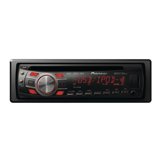
CD RDS RECEIVER
DEH-3300UB
DEH-3390UB
DEH-3350UB
DEH-3350UB
DEH-3350UB
DEH-3350UB
This service manual should be used together with the following manual(s):
Model No.
Order No.
CX-3269
CRT4488
For details, refer to "Important Check Points for Good Servicing".
PIONEER CORPORATION
PIONEER ELECTRONICS (USA) INC. P.O. Box 1760, Long Beach, CA 90801-1760, U.S.A.
PIONEER EUROPE NV Haven 1087, Keetberglaan 1, 9120 Melsele, Belgium
PIONEER ELECTRONICS ASIACENTRE PTE. LTD. 253 Alexandra Road, #04-01, Singapore 159936
PIONEER CORPORATION 2010
Mech. Module
S11.1STD-DOUT
CD Mech. Module : Circuit Descriptions, Mech. Descriptions, Disassembly
1-1, Shin-ogura, Saiwai-ku, Kawasaki-shi, Kanagawa 212-0031, Japan
DEH-3300UB/XSUC
/XNID
/XNES
/X1NEC
/XSES
/XNES1
Remarks
ORDER NO.
CRT4634
/XSUC
K-ZZZ OCT. 2010 Printed in Japan
Advertisement
Table of Contents

Related Manuals for Pioneer DEH-3300UB/XSUC


Summary of Contents for Pioneer DEH-3300UB/XSUC
- Page 1 PIONEER CORPORATION 1-1, Shin-ogura, Saiwai-ku, Kawasaki-shi, Kanagawa 212-0031, Japan PIONEER ELECTRONICS (USA) INC. P.O. Box 1760, Long Beach, CA 90801-1760, U.S.A. PIONEER EUROPE NV Haven 1087, Keetberglaan 1, 9120 Melsele, Belgium PIONEER ELECTRONICS ASIACENTRE PTE. LTD. 253 Alexandra Road, #04-01, Singapore 159936 PIONEER CORPORATION 2010 K-ZZZ OCT.
-
Page 2: Safety Information
The AEL (accessible emission level )of the laser power output is less than CLASS 1 but the laser component is capable of emitting radiation exceeding the limit for CLASS 1. A specially instructed person should do servicing operation of the apparatus. DEH-3300UB/XSUC... - Page 3 CAUTION Danger of explosion if battery is incorrectly replaced. Replaced only with the same or equivalent type recommended by the manufacture. Discord used batteries according to the manufacture's instructions. DEH-3300UB/XSUC...
- Page 4 To protect products from damages or failures during transit, the shipping mode should be set or the shipping screws should be installed before shipment. Please be sure to follow this method especially if it is specified in this manual. DEH-3300UB/XSUC...
-
Page 5: Table Of Contents
10.1 TUNER AMP UNIT (GUIDE PAGE) ......................40 10.2 KEYBOARD UNIT ..........................46 10.3 CD CORE UNIT (S11.1STD-DOUT) ......................48 10.4 WAVEFORMS............................50 11. PCB CONNECTION DIAGRAM ........................52 11.1 TUNER AMP UNIT ..........................52 11.2 KEYBOARD UNIT ..........................56 11.3 CD CORE UNIT (S11.1STD-DOUT) ......................58 12. ELECTRICAL PARTS LIST ...........................60 DEH-3300UB/XSUC... -
Page 6: Service Precautions
If the lead is bent, please correct the angle between the lead and the light receiving part to be 90 degrees or replace the infrared deteching unit for remote control (GP1UXC14RK). DEH-3300UB/XSUC... - Page 7 * length of tape : 24 ± 4 mm 10. Capacitor Bond Lock (ID, ES, EC, ES1) Silicon Glue (GEM1017) Place the capacitor in the center of the silk print, and confirm it does not touch to the connector. Then, apply silicon glue. DEH-3300UB/XSUC...
-
Page 8: Notes On Soldering
Compared with eutectic solders, lead-free solders have higher bond strengths but slower wetting times and higher melting temperatures (hard to melt/easy to harden). The following lead-free solders are available as service parts: Parts numbers of lead-free solder: GYP1006 1.0 in dia. GYP1007 0.6 in dia. GYP1008 0.3 in dia. DEH-3300UB/XSUC... -
Page 9: Specifications
2. SPECIFICATIONS 2.1 SPECIFICATIONS DEH-4300UB/XNUC, DEH-3300UB/XSUC General WMA decoding format ..Ver. 7, 7.1, 8, 9, 10, 11, 12 Power source......14.4 V DC (10.8 V to 15.1 V allowable) (2ch audio) Grounding system....Negative type (Windows Media Player) MP3 decoding format ...MPEG-1 & 2 Audio Layer 3 Maximum current consumption WAV signal format ....Linear PCM &... -
Page 10: Disc/Content Format
Signal-to-noise ratio....94 dB (1 kHz) (IEC-A net- work) Number of channels ....2 (stereo) WMA decoding format ..Ver. 7, 7.1, 8, 9, 10, 11, 12 (2ch audio) (Windows Media Player) MP3 decoding format ...MPEG-1 & 2 Audio Layer 3 2.2 DISC/CONTENT FORMAT DEH-3300UB/XSUC... -
Page 11: Panel Facilities
Indicator State Tuner: band and frequency CAUTION Main dis- Built-in CD, USB storage de- Use an optional Pioneer USB cable (CD-U50E) play sec- vice and iPod: elapsed play- tion to connect the USB audio player/USB mem- back time and text... -
Page 12: Connection Diagram
If you do not plan to detach the front panel, 9 Gray/black the front panel can be fastened with the supplied a Green screw. b Green/black c Violet d Violet/black e Black (chassis ground) Screw (BPZ20P060FTC) (UC) Connect to a clean, paint-free metal location. (XXX7020) (ID, ES) DEH-3300UB/XSUC... -
Page 13: Basic Items For Service
See the table below for the items to be checked regarding audio: Item to be checked regarding audio Distortion Noise Volume too low Volume too high Volume fluctuating Sound interrupted DEH-3300UB/XSUC... -
Page 14: Pcb Locations
3.2 PCB LOCATIONS CD Core Unit (S11.1STD-DOUT) Tuner Amp Unit Keyboard Unit A:DEH-3300UB/XSUC B:DEH-3390UB/XNID C:DEH-3350UB/XNES D:DEH-3350UB/X1NEC E:DEH-3350UB/XSES F:DEH-3350UB/XNES1 Unit Number : CWN5477(A) : CWN5478(B,C,D,E,F) Unit Name : Tuner Amp Unit Unit Number Unit Name : Keyboard Unit Unit Number : CWX3985 Unit Name : CD Core Unit (S11.1STD-DOUT) -
Page 15: Jigs List
Capacitor Bond Lock 3.4 CLEANING Before shipping out the product, be sure to clean the following portions by using the prescribed cleaning tools: Portions to be cleaned Cleaning tools CD pickup lenses Cleaning liquid : GEM1004 Cleaning paper : GED-008 DEH-3300UB/XSUC... -
Page 16: Block Diagram
VO3+ SPINDLE MOTOR LDIN LOEJ VO3- CLCONT LCOM MUTE RESET RESET LOADING/CARRIAGE VO4+ CONT RESET CDRST LCOP MOTOR VO4- CD DATA (CDSRQ,CDSTBY,SKIP, CD DATA (CDSRQ,CDSTBY,SKIP, SCL,SDA,DATA,BCLK,LRCK,WAIT) SCL,SDA,DATA,BCLK,LRCK,WAIT) DSCSNS :DEH-3300UB/XSUC HOME :DEH-3390UB/XNID S903 S901 DSCSNS HOME :DEH-3350UB/XNES :DEH-3350UB/XNEC :DEH-3350UB/XSES :DEH-3350UB/XNES1 DEH-3300UB/XSUC... - Page 17 LCD DRIVER/ TC7SET08FUS1 KEY CONTROLLER KST4 DPDT DPDT DPDT IC1801 DPDT VDSENS PD6340A DSENS DSENS DSENS V1801 B.UP REMOTE CONTROL SENSOR VDCONT IC1802 GP1UXC14RK ILM+B ILM+B CDRST D1868,D1869,D1870,D1871, D1872,D1873,D1874,D1875, SW5V D1913 D1876,D1877,D1878,D1879, SWVDD SW5V D1880,D1881,D1882,D1883 CN1911 USB5V USB5V USB5V DEH-3300UB/XSUC...
-
Page 18: Diagnosis
In case of the above signal, the communication Source keys with Grille microcomputer may fail. operative If the time interval is not 300 msec, the oscillator may be defective. Source ON SYSPW <- H Pin 7 Completes power-on operation. (After that, proceed to each source operation) DEH-3300UB/XSUC... -
Page 19: Error Code List
• How to restore from each error is shown below. classification, shown below. 0x, 1x and 3x: ACC-OFF then ON, CD-OFF then ON, 0x: Servo-related errors Disc ejection 1x: Servo-related errors 5X: ACC-OFF then ON, Disc ejection, Disc reloading 3x: Servo-related errors 5x: Mechanism-related errors DEH-3300UB/XSUC... - Page 20 Once the iPod's main menu is displayed, recon- nect the iPod and reset it. STOP There are no Select a list that songs in the cur- contains songs. rent list. NOT FOUND No related songs Transfer songs to the iPod. DEH-3300UB/XSUC...
-
Page 21: Connector Function Description
5.3 CONNECTOR FUNCTION DESCRIPTION ANTENNA WIRED REMOTE CONTROL (Except DEH-3300UB/XSUC) 15 13 11 9 7 5 3 1 16 14 12 10 8 6 4 2 REAR OUTPUT SUBWOOFER OUTPUT 1 FL+ 9 NC 2 FR+ 10 NC FRONT OUTPUT... -
Page 22: Service Mode
The screen gets still when entering this item. On (an initial value or On (state when setting value of default entering test mode) Switching to next display menu) by pressing “ 1 ” + “ 3 ” keys simultaneously. DEH-3300UB/XSUC... -
Page 23: Cd Test Mode
When the power is turned on/off the gain of the RFAMP is reset to 0 dB. At the same time all the self-adjusting values shall return to the default setting. Do not do Tracking Servo Close before doing Focus Servo Close. (Because the overcurrent flows) DEH-3300UB/XSUC... -
Page 24: Disassembly
Lift off the Tuner Amp Assy from the Heat sink side. The Tuner Amp Unit is fixed into the ditch. Disconnect the FFC and then remove the CD Mechanism Module. CD Mechanism Module Fig.4 DEH-3300UB/XSUC... - Page 25 Remove the two screws. Straighten the tabs at two locations indicated and then remove the Tuner Amp Unit. Fig.5 Tuner Amp Unit Attention of removing (Fig.6) Don't remove this screws excluding the dismantlement of the CD Mechanism Module. Fig.6 DEH-3300UB/XSUC...
- Page 26 1. Attach the button from the front side of the panel. Fig.9 2. Attach the spring to the arm as shown in the figure. The bended tip of the spring is set to this side. Hitch the spring to the groove. Fig.10 DEH-3300UB/XSUC...
- Page 27 4. Fit the boss on the lower side of the arm in the lower hole of the panel, and then warp the rib on the panel in the direction shown in the figure and fit the boss of the arm in the panel. Fig.11 DEH-3300UB/XSUC...
- Page 28 2. Be careful not to hold the solid line portions or the CRG mecha part or insert foreign substances, to prevent distortion. 3. When holding the sides of the upper chassis, do not apply excessive force to prevent distortion. (Approx. 8N or less) Correct way of holding the unit Incorrect way of holding the unit DEH-3300UB/XSUC...
- Page 29 1. Create an empty clamp state according to “How to create empty clamp state of mecha module”. 2. Apply 1.5 V to the CRG motor and move the PU to the outer circumference. (Caution) After moving the PU to the outer circumference and performing necessary treatment, make sure to solder the lead wires. DEH-3300UB/XSUC...
-
Page 30: Each Setting And Adjustment
1k ohms in series. The load and eject operation is not guarantied with the mechanism upside down. If the mechanism is blocked due to mistaken eject operation, reset the product or turn off and on the ACC to restore it. DEH-3300UB/XSUC... -
Page 31: Checking The Grating After Changing The Pickup Unit
Because of eccentricity in the disc and a slight misalignment of the clamping center the grating waveform may be seen to "wobble" ( the phase difference changes as the disc rotates). The angle specified above indicates the average angle. Hint Reloading the disc changes the clamp position and may decrease the "wobble". DEH-3300UB/XSUC... - Page 32 Grating waveform Ech -> Xch 20 mV/div, AC Fch -> Ych 20 mV/div, AC 0 degrees 30 degrees 45 degrees 60 degrees 75 degrees 90 degrees DEH-3300UB/XSUC...
-
Page 33: Pcl Output Confirmation
With the TESTIN (22 pin) status of IC601 to be “H”, it is shifted to PCL Output Test mode after reset started. Check that square wave of 600.0 kHz is output from PCL (8 Pin) of IC601. If clock signal is out of this range, this resonator (X602) must be changed for a new one. DEH-3300UB/XSUC... -
Page 34: Exploded Views And Parts List
Screw adjacent to mark on the product are used for disassembly. For the applying amount of lubricants or glue, follow the instructions in this manual. (In the case of no amount instructions,apply as you think it appropriate.) 9.1 PACKING DEH-3300UB/XSUC... - Page 35 Not used Not used Not used CRY1250 18-3 Service Network Not used CRY1305 Not used Not used Not used CRY1251 Owner's Manual,Installation Manual Part No. Language CRD4525 English, French, Spanish(Espanol) CRB3473 English CRD4527 English, Spanish(Espanol), Portuguese(B), Traditional Chinese, Arabic, Persian DEH-3300UB/XSUC...
-
Page 36: Exterior
9.2 EXTERIOR DEH-3390UB/XNID DEH-3350UB/XNES DEH-3350UB/X1NEC DEH-3350UB/XSES DEH-3350UB/XNES1 DEH-3300UB/XSUC... - Page 37 Rubber Contact QNV3023 Cord Assy See Contrast table (2) Connector YNV5192 Knob Unit CXE3692 (2) CONTRAST TABLE DEH-3300UB/XSUC, DEH-3390UB/XNID, DEH-3350UB/XNES, DEH-3350UB/X1NEC, DEH-3350UB/XSES and DEH-3350UB/XNES1 are constructed the same except for the following: DEH-3300UB/ DEH-3390UB/ DEH-3350UB/ DEH-3350UB/ DEH-3350UB/ DEH-3350UB/ Mark No.
-
Page 38: Cd Mechanism Module
( C ) ( A ) ( A ) ( A ) ( C ) ( C ) ( A ) : GEM1045 ( B ) : GEM1038 ( C ) : GEM1024 ( C ) ( D ) : GEM1043 DEH-3300UB/XSUC... - Page 39 CNV8342 Guide CNW1171 Roller CNW1172 CNW2157 CNW1174 Roller CNW1175 Lever CNW1176 CNW1177 CNW1178 Gear CNW1180 Gear CNW1181 ..Gear CNW1183 Rack CNW1184 Gear CNW1185 Gear CNW1186 Gear CNW1187 Gear CNW1188 Clamper CNW1190 CNW1192 Holder CNW1193 Holder CNW1194 Damper CNW1197 DEH-3300UB/XSUC...
-
Page 40: Schematic Diagram
MECHA VD 751 - 800 ILMG DGND ILMGND C803 DGND DGND C802 The > mark found on some component parts indicates the importance of the safety factor of the part. GRILL Therefore, when replacing, be sure to use parts of identical designation. DEH-3300UB/XSUC... - Page 41 1u/10 TUNER AMP UNIT C208 1u/10 C206 1u/10 C234 CCG1192-A (DCH1201-A) C235 R232 E-VOL FM(30%): -5.9 dBs A : DEH-3300UB/XSUC AM(30%): -5.9 dBs AUX:+10.3 dBs B : DEH-3390UB/XNID CD/USB:+10.2 dBs C205 1u/10 C : DEH-3350UB/XNES C209 1u/10 C207 main 1u/10...
- Page 42 DEH-3300UB/XSUC...
- Page 43 DEH-3300UB/XSUC...
- Page 44 DEH-3300UB/XSUC...
- Page 45 DEH-3300UB/XSUC...
-
Page 46: Keyboard Unit
MODA KST3 5.00MHz SEG8 SEG8 KYDT SEG7 S184 S1839 SEG7 SEG6 DPDT SEG6 SEG5 S1829 S1840 DGND SEG5 CLOCK S184 KST4 EJECT 2.2k L1801 R1805 2.2k R1806 IC1802 GP1UXC14RK DGND R1802 R1804 DGND CLEAR BUTTON CAW1998 V1801 ILMGND COLOR2 DEH-3300UB/XSUC... - Page 47 DEH-3300UB/XSUC KEYBOARD UNIT DEH-3390UB/XNID DEH-3350UB/XNES DEH-3350UB/X1NEC DEH-3350UB/XSES DEH-3350UB/XNES1 CN1821 CN1901 ILMGND CKS6287-A CKN1082-A R1902 DGND R1901 ILMGND SW5V S1827 DGND AUX:+2.2 dBs ROT1 1826 S1828 ILM+B ROT0 CSD1168-A USBGND KYDT DPDT CN801 S1832 BAND USB5V S1845 MULTI-CONTROL ILMCLR1 S1835 DGND...
-
Page 48: Cd Core Unit (S11.1Std-Dout)
MOTOR DRIVER LOGIC TABLE PowVcc2 1u/10 VO1- VO4- LOAD PLAY (1608) (1608) VO1+ VO4+ CLCONT VO2- VO3- LOEJ SWITCHES: CD CORE UNIT VO2+ VO3+ CONT S901:HOME SWITCH..ON-OFF IC301 S903:DSCSNS SWITCH..ON-OFF BA5839FP S905:8EJ SWITCH....ON-OFF The underlined indicates the switch position. PGND DEH-3300UB/XSUC... - Page 49 3.3V LRCK 10 GND R606 BCLK DATA 11 DATA NM (1608) DATA BCLK 12 BCLK LRCK 13 LRCK AAGND1 AAGND2 14 GND 15 PGND /WAIT 16 WAIT i h g PGND NO MOUNT PARTS (NM) Land for manual soldering DEH-3300UB/XSUC...
-
Page 50: Waveforms
500 s/div fRFAGC 500 mV/div 500 mV/div 500 mV/div 9TIN 500 mV/div Focus Search waveform Track Open waveform 100 Track Jump waveform (32 Track Jump x 3) Ref.: Ref.: Ref.: REFO REFO REFO Mode: Mode: Mode: TEST TEST TEST DEH-3300UB/XSUC... - Page 51 12 cm CD Eject operation Ref.: Ref.: Ref.: REFO AGND Mode: Mode: Mode: Normal Normal Normal fRFAGC 1 V/div 500 s/div 9TIN 1 V/div 1 V/div aFIN 1 V/div Black Dot (800 m) during play Ref.: REFO Mode: Normal DEH-3300UB/XSUC...
-
Page 52: Pcb Connection Diagram
2.Viewpoint of PCB diagrams JA251 PRE OUT C259 Capacitor Connector SIDE A C316 Q251 R252 C252 C260 Q252 P251 C251 C313 C254 C253 D502 C261 SIDE B IC501 Chip Part P.C.Board C505 C503 R501 C502 R503 R502 R506 IC502 R507 CN701 FRONT DEH-3300UB/XSUC... - Page 53 R702 R713 R718 IC912 R714 R719 R715 R720 R638 R717 R716 R816 C852 C817 R872 R821 R822 IC801 C802 C812 L851 C851 C808 L802 C803 R851 R691 C801 C806 S691 R818 CN802 D808 R819 C818 R823 CN1821 CN801 FRONT DEH-3300UB/XSUC...
- Page 54 TUNER AMP UNIT TESTIN DEH-3300UB/XSUC...
- Page 55 SIDE B DEH-3300UB/XSUC...
-
Page 56: Keyboard Unit
11.2 KEYBOARD UNIT KEYBOARD UNIT SIDE A D1863 D1880 D1864 D1881 D1865 D1882 C1863 D1862 D1883 D1861 D1879 C1861 D1860 D1878 C1855 D1854 D1877 D1858 D1856 C1858 D1874 D1876 D1873 D1867 DEH-3300UB/XSUC... - Page 57 KEYBOARD UNIT SIDE B C1801 R1802 R1866 R1873 VA1901 VA1902 C1902 C1901 VA1903 C1903 CN801 R1891 R1899 R1888 R1880 R1895 R1872 R1854 R1864 R1898 R1874 R1852 R1868 R1860 R1862 R1853 R1882 R1881 R1871 R1897 R1858 DEH-3300UB/XSUC...
-
Page 58: Cd Core Unit (S11.1Std-Dout)
C213 C214 R215 R306 C215 R308 C305 C304 C203 C238 C307 C212 C240 C299 IC201 R307 R305 C207 C204 R707 C209 X201 R294 IC301 R264 C702 R225 R282 C211 R708 C210 R232 R709 R281 C306 R710 C701 CN701 CN701 DEH-3300UB/XSUC... - Page 59 C231 C232 S905 C233 R237 R723 R721 R722 R260 R702 R297 R701 R283 R242 R602 C283 C281 C602 R292 R291 C282 R243 R606 R604 DSCSNS R299 R601 R706 C708 R293 C601 S903 C705 C703 R603 C710 C284 C707 R711 DEH-3300UB/XSUC...
-
Page 60: Electrical Parts List
IC 301 (A, 91, 111) IC NJM2068V Circuit Symbol and No. Part No. Circuit Symbol and No. Part No. IC 912 (A,145,28) IC BA49182-V12 A:DEH-3300UB/XSUC Q 251 (A,23,131) Chip Transistor RN1910 B:DEH-3390UB/XNID Q 252 (A,13,129) Chip Transistor(B,C,D,E,F) RN1910 Q 351... - Page 61 R 505 (A,26,113) RS1/16SS183J R 752 (A,97,47) RS1/16SS103J R 506 (A,15,114) RS1/16SS513J R 753 (A,139,134) RS1/10SR821J R 508 (A,95,67) RS1/16SS103J R 801 (A,117,30) RS1/10SR101J R 551 (A,121,95) RS1/16SS473J R 802 (A,119,30) RS1/10SR101J R 806 (A,105,25) RS1/10SR222J R 552 (A,117,85) RS1/16SS103J DEH-3300UB/XSUC...
- Page 62 C 503 (A,32,120) CEVQW221M6R3 C 302 (A,81,128) CKSRYB474K10 C 303 (A,76,128) CKSRYB474K10 C 504 (A,44,123) CKSRYB105K10 C 304 (A,80,128) CKSRYB474K10 C 505 (A,12,121) CEJQ221M16 C 305 (A,74,132) CKSRYB474K10 C 506 (A,27,113) CKSSYB153K16 C 306 (A,81,132) CKSRYB474K10 C 508 (A,25,114) CCSSCH220J50 DEH-3300UB/XSUC...
- Page 63 CKSSYB102K50 R 1804 (B,147,30) RS1/10SR101J C 920 (A,147,42) 4.7 uF CCG1201 R 1805 (B,74,18) RS1/10SR222J C 921 (A,133,40) CKSRYB104K16 R 1806 (B,73,16) RS1/10SR222J C 922 (A,155,52) CEAT102M16(P30) R 1822 (B,55,28) RS1/10SR273J C 923 (A,154,40) CKSSYB102K50 R 1823 (A,146,4) RS1/10SR0R0J DEH-3300UB/XSUC...
- Page 64 R 240 (B,26,30) RS1/16SS473J Miscellaneous Parts List R 245 (B,28,30) RS1/16SS104J R 254 (B,29,30) RS1/16SS104J R 260 (B,41,21) RS1/16SS103J Motor Unit(SPDL) CXE2273 Motor Unit(LOAD/CRG) CXC4026 R 262 (A,44,32) RS1/16SS472J Pickup Unit(S10.5)(Service) CXX1942 R 263 (A,47,32) RS1/16SS472J R 264 (A,44,25) RS1/16SS102J DEH-3300UB/XSUC...