Fujitsu M10-4 Service Manual
Hide thumbs
Also See for Fujitsu M10-4:
- Service manual (514 pages) ,
- Safety and compliance manual (63 pages) ,
- Service manual (514 pages)
Table of Contents
Advertisement
Quick Links
Download this manual
See also:
Service Manual
Advertisement
Table of Contents
Troubleshooting

Related Manuals for Fujitsu Fujitsu M10-4


Summary of Contents for Fujitsu Fujitsu M10-4
- Page 1 Fujitsu M10-4/Fujitsu M10-4S/ SPARC M10-4/SPARC M10-4S Service Manual Manual Code: C120-E682-10EN November 2014...
- Page 2 The furnishings of this document to you does not give you any rights or licenses, express or implied, with respect to the product or technology to which it pertains, and this document does not contain or represent any commitment of any kind on the part of Oracle or Fujitsu Limited or any affiliate of either of them.
-
Page 3: Table Of Contents
Contents Preface xi Chapter 1 Before Starting Maintenance Work 1 1.1 Warning/Caution Indications 1 1.2 Warning Labels 2 1.3 Labels/Tags 2 1.4 Safety Precautions 4 1.5 Notes Regarding Static Electricity 5 1.6 Other Precautions 6 1.7 ... - Page 4 5.3.3 Checking the usage status of the internal disk 56 5.4 Preparations for Enabling Active Maintenance 56 5.4.1 Releasing the assignment of I/O devices 56 Fujitsu M10-4/Fujitsu M10-4S/SPARC M10-4/SPARC M10-4S Service Manual ・ November 2014...
- Page 5 5.4.2 Enabling the removal of an I/O device 61 5.4.3 Releasing a chassis requiring maintenance from the physical partition 69 5.5 Powering Off the Physical Partition Requiring Maintenance 71 5.6 Stopping the Entire System 73 5.6.1 ...
- Page 6 7.4.1 Active removal 153 7.4.2 Inactive removal 158 7.4.3 System-stopped removal 162 Chapter 8 Maintaining the PCI Express Cards 169 8.1 Configuration of the PCI Express Cards 169 Fujitsu M10-4/Fujitsu M10-4S/SPARC M10-4/SPARC M10-4S Service Manual ・ November 2014...
- Page 7 8.2 Maintenance Flow 171 8.3 Removing a PCI Express Card 172 8.3.1 Removing a PCI Express card cassette 172 8.3.2 Removing a PCI Express card 174 8.3.3 Installing a PCI Express card filler 177 8.4 ...
- Page 8 Chapter 16 Maintaining the XSCF BB Control Cables 291 16.1 Configuration of the Ports for the XSCF BB Control Cables 291 16.2 Removing an XSCF BB Control Cable 293 Fujitsu M10-4/Fujitsu M10-4S/SPARC M10-4/SPARC M10-4S Service Manual ・ November 2014 viii...
- Page 9 16.3 Installing an XSCF BB Control Cable 294 Chapter 17 Maintaining the XSCF DUAL Control Cables 297 17.1 Configuration of the XSCF DUAL Control Ports 297 17.2 Removing an XSCF DUAL Control Cable 299 17.3 Installing an XSCF DUAL Control Cable 300 Appendix A Component List 301 Appendix B Component Specifications 303 B.1 ...
- Page 10 Fujitsu M10-4/Fujitsu M10-4S/SPARC M10-4/SPARC M10-4S Service Manual ・ November 2014...
-
Page 11: Preface
M10-4/M10-4S. The maintenance work should be performed by service engineers and/or field engineers. See the Crossbar Box for Fujitsu M10/SPARC M10 Systems Service Manual for the procedures for maintaining the crossbar box. Fujitsu M10 is sold as SPARC M10 Systems by Fujitsu in Japan. -
Page 12: Related Documentation
*1: The listed manuals are subject to change without notice. *2: Printed manuals are provided with the product. *3: This document applies specifically to the SPARC M10 and FUJITSU ETERNUS disk storage system. Fujitsu M10-4/Fujitsu M10-4S/SPARC M10-4/SPARC M10-4S Service Manual ・ November 2014... -
Page 13: Text Conventions
Each command has a section number in a command name to prompt users to refer to Notes on Safety Read the following documents thoroughly before using or handling any SPARC M10 Systems. Fujitsu M10/SPARC M10 Systems Important Legal and Safety Information ■ Fujitsu M10/SPARC M10 Systems Safety and Compliance Guide ■... -
Page 14: Document Feedback
Japanese site ■ http://jp.fujitsu.com/platform/server/sparc/manual/ Global site ■ http://www.fujitsu.com/global/services/computing/server/sparc/downloads/manual/ Fujitsu M10-4/Fujitsu M10-4S/SPARC M10-4/SPARC M10-4S Service Manual ・ November 2014... -
Page 15: Chapter 1 Before Starting Maintenance Work
Chapter 1 Before Starting Maintenance Work This chapter describes the safety precautions that must be observed before starting any maintenance work. Note the meanings of each of the following symbols and labels to ensure that the work is done correctly. Warning/Caution Indications ■... -
Page 16: Warning Labels
The standard label (B in Figure 1-2) describes the following certification standards. ■ Safety: NRTL/C ■ Radio wave: VCCI-A, FCC-A, DOC-A, and KCC ■ Safety and radio wave: CE, BSMI, RCM, and EAC ■ Fujitsu M10-4/Fujitsu M10-4S/SPARC M10-4/SPARC M10-4S Service Manual ・ November 2014... - Page 17 Figure 1-2 Location of the system name plate label and standard label The RFID tag (Figure 1-3) carries an Asset ID. The RFID tag of the SPARC ■ M10-4/M10-4S is affixed on the front cover. Chapter 1 Before Starting Maintenance Work...
-
Page 18: Safety Precautions
Contact a service engineer to inspect the chassis. ■ Fujitsu M10-4/Fujitsu M10-4S/SPARC M10-4/SPARC M10-4S Service Manual ・ November 2014... -
Page 19: Notes Regarding Static Electricity
■ printed boards. Use grounded power outlets. ■ Do not attempt to make any mechanical or electrical modifications. Fujitsu shall ■ not be responsible for the regulatory compliance of a chassis that has been modified. Safety precautions on the racks The racks should be fixed on the floor, ceiling, or the adjacent frame. -
Page 20: Other Precautions
If a component is mounted with a bent pin in a connector, the chassis or component may be damaged. Also, carefully proceed with the work to prevent any pin from being bent. Fujitsu M10-4/Fujitsu M10-4S/SPARC M10-4/SPARC M10-4S Service Manual ・ November 2014... -
Page 21: Emergency Power Off
If excessive force is applied to the CPU memory unit, the components mounted on ■ printed boards may be damaged. When handling the CPU memory unit, observe the following precautions: Hold the CPU memory unit by the metal frame. ■ When removing the CPU memory unit from the packaging, keep the CPU ■... - Page 22 Figure 1-5 Removing the power cords Fujitsu M10-4/Fujitsu M10-4S/SPARC M10-4/SPARC M10-4S Service Manual ・ November 2014...
-
Page 23: Chapter 2 Understanding The System Components
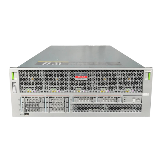
Chapter 2 Understanding the System Components This section describes the components mounted on the SPARC M10-4/M10-4S. It is necessary to confirm and fully understand the configurations of the components mounted in the chassis as well as the LED indications before starting any maintenance work. - Page 24 Figure 2-1 Location of components that can be accessed from the front Location number Component Fan unit Internal disk Power supply unit Fujitsu M10-4/Fujitsu M10-4S/SPARC M10-4/SPARC M10-4S Service Manual ・ November 2014...
- Page 25 Components that can be accessed from the rear Figure 2-2 Location of components that can be accessed from the rear Location number Component PCI-Express (PCIe) card cassette Crossbar unit (Only for the SPARC M10-4S. The SPARC M10-4 incorporates three PCIe card cassettes.) Chapter 2 Understanding the System Components...
- Page 26 Internal components To access internal components, remove the CPU memory unit from the chassis. Figure 2-3 Locations of internal components Fujitsu M10-4/Fujitsu M10-4S/SPARC M10-4/SPARC M10-4S Service Manual ・ November 2014...
-
Page 27: Checking The Memory Configuration Rules
Figure 2-4 CPU memory unit removed from the chassis Location number Component CPU memory unit upper CPU memory unit lower Memory (CPU memory unit upper) PSU backplane unit Operation panel Note - Two CPUs are directly installed on each of the CPU memory unit upper and CPU memory unit lower. -
Page 28: Memory Installation Rules
For example, in the memory on the right side of CMUL CPU#0 in Figure 2-5, the four-module set of MEM#00B, MEM#00A, MEM#01B, and MEM#01A mirrors the four-module set of MEM#04B, MEM#04A, MEM#05B, and MEM#05A. Fujitsu M10-4/Fujitsu M10-4S/SPARC M10-4/SPARC M10-4S Service Manual ・ November 2014... - Page 29 Figure 2-5 Mounting locations and units of memory Mirroring Mirroring CMUL CPU#0 CPU#1 Front CMUU CPU#0 CPU#1 Front Chapter 2 Understanding the System Components...
- Page 30 If you mount memory by expanding a CPU memory unit upper to a chassis in which only a CPU memory unit lower is mounted, you do not have to remove the memory mounted on the CPU memory unit lower. Fujitsu M10-4/Fujitsu M10-4S/SPARC M10-4/SPARC M10-4S Service Manual ・ November 2014...
-
Page 31: Checking Memory Information
Install it by observing the mounting configurations shown in either Table 2-3or Table 2-2. Table 2-3 Memory mounting configurations (CMUL and expanded CMUU) Number of Mounted memory memory modules a in Figure 2-3 a in b in Figure 2-3 Figure 2-3 a in b in... -
Page 32: Confirming The Functions Of The Operation Panel
Note - In a building block configuration with a crossbar box connected, only the operation panel of the crossbar box that is the master XSCF can have all the operation panel functions enabled. Fujitsu M10-4/Fujitsu M10-4S/SPARC M10-4/SPARC M10-4S Service Manual ・ November 2014... - Page 33 Figure 2-7 Location of the operation panel Figure 2-8 Appearance of operation panel Location number Component POWER LED Chapter 2 Understanding the System Components...
-
Page 34: Display Function Of The Operation Panel
The operation panel has three LED indicators to implement its display function. The LED indicators indicate the following. For details, see "2.4.1 Operation panel LEDs." General system status ■ System error warning ■ System error location ■ Fujitsu M10-4/Fujitsu M10-4S/SPARC M10-4/SPARC M10-4S Service Manual ・ November 2014... -
Page 35: Control Function Of The Operation Panel
Figure 2-9 Operation panel LEDs Location number Component POWER LED XSCF STANDBY LED CHECK LED 2.3.2 Control function of the operation panel The operation panel has the following switches to implement its control function: BB-ID switch ■ Identifies the SPARC M10-4S. Mode switch (slide switch) ■... - Page 36 4 (*1): seconds) If the system is stopped in Operation is ignored. Service mode: If the system has been Operation is ignored. started in Locked mode (*1): Fujitsu M10-4/Fujitsu M10-4S/SPARC M10-4/SPARC M10-4S Service Manual ・ November 2014...
- Page 37 Table 2-7 Functions of the power switch (continued) Icon Operation Description If the system is stopped in Starts the system. Locked mode: At this time, if a wait time for the air conditioning facilities or a warm-up time is set on the XSCF, the processing for waiting for the power-on of the air conditioning facilities and the completion of warm-up is omitted.
-
Page 38: Checking The Led Indications
● being supplied. Blinking (*1): Indicates that the chassis requires ● maintenance (this function is also referred to as the "locator"). *1 The blink interval is 1 second (1 Hz). Fujitsu M10-4/Fujitsu M10-4S/SPARC M10-4/SPARC M10-4S Service Manual ・ November 2014... -
Page 39: Leds On The Rear Panel (System Locator)
Table 2-10 System status indicated by combination of LEDs LED state Description POWER XSCF CHECK STANDBY Power is disconnected. Power has just been turned on. The XSCF has detected an error. Blinking The XSCF is being initialized. (*1) The XSCF is in the standby state. -
Page 40: Leds On Each Component
Each component of the SPARC M10-4/M10-4S has a mounted LED. These LEDs light to indicate that a component requires maintenance if that component experiences a fault. Start maintenance work after checking the LED status. Fujitsu M10-4/Fujitsu M10-4S/SPARC M10-4/SPARC M10-4S Service Manual ・ November 2014... - Page 41 The LEDs on each component and their statuses are as follows: Table 2-12 LEDs on the XSCF or XSCF unit and their states Name Color Status Description READY Green Indicates that the component is operating. The component cannot be released and removed from the system.
- Page 42 Blinking Indicates that the component requires (*1) maintenance (This function is also referred to as the "locator"). Indicates the normal state. *1 The blink interval is 1 second (1 Hz). Fujitsu M10-4/Fujitsu M10-4S/SPARC M10-4/SPARC M10-4S Service Manual ・ November 2014...
-
Page 43: Confirming The Types Of Cable
Table 2-17 LEDs on the internal disk and their states Name Color Status Description READY Green Blinking Indicates that the disk is being accessed. This LED is normally on, but it blinks while the disk is being accessed. While the LED is blinking, maintenance work such as the removal of the disk cannot be performed. -
Page 44: Cable Connection Ports
Chapter 17 Maintaining the XSCF DUAL Control Cables ■ Figure 2-12 Locations of cable connection ports (SPARC M10-4S) Location number Connection port XSCF DUAL control port XSCF BB control port Fujitsu M10-4/Fujitsu M10-4S/SPARC M10-4/SPARC M10-4S Service Manual ・ November 2014... - Page 45 Location number Connection port Crossbar cable connection port Chapter 2 Understanding the System Components...
- Page 46 Fujitsu M10-4/Fujitsu M10-4S/SPARC M10-4/SPARC M10-4S Service Manual ・ November 2014...
-
Page 47: Chapter 3 Type Of Maintenance
Chapter 3 Type of Maintenance This chapter describes the types of maintenance performed on the SPARC M10-4 and SPARC M10-4S. Types of Maintenance Supported in the SPARC M10-4/M10-4S ■ Active Maintenance ■ Inactive Maintenance ■ System-stopped Maintenance ■ Note that the terms used in this manual are defined as follows. Table 3-1 ... -
Page 48: Active Maintenance
CPU memory unit Memory Crossbar unit (*1) Power supply unit OK (*3) OK (*3) Fan unit OK (*3) OK (*3) Internal disk OK (*4) OK (*4) PCIe card OK (*5) OK (*5) Fujitsu M10-4/Fujitsu M10-4S/SPARC M10-4/SPARC M10-4S Service Manual ・ November 2014... -
Page 49: Inactive Maintenance
Table 3-2 Whether active maintenance (replacement/addition/removal) is enabled for each FRU (continued) -: Maintenance cannot be performed. Single-chassis configuration Building block configuration Active/hot maintenance Active/hot maintenance Active/cold maintenance (*6) PSU backplane unit Operation panel Crossbar cable (*2) XSCF BB control cable (*2) XSCF DUAL control cable (*2) *1 The unit is mounted only in the SPARC M10-4S. -
Page 50: System-Stopped Maintenance
XSCF DUAL control cable (*2) *1 The unit is mounted only in the SPARC M10-4S. *2 The cable is mounted only in a building block configuration using the SPARC M10-4S. Fujitsu M10-4/Fujitsu M10-4S/SPARC M10-4/SPARC M10-4S Service Manual ・ November 2014... -
Page 51: Chapter 4 Preparation And Precautions For Maintenance
Chapter 4 Preparation and Precautions for Maintenance This chapter describes preparations that must be completed prior to maintenance and the precautions for various work and maintenance. Confirming the System Configuration ■ Troubleshooting ■ Maintenance Precautions ■ Confirming the System Configuration This section explains how to check the hardware and software configurations. -
Page 52: Confirming The Software And Firmware Configurations
For details on logging in to the control domain console, see "8.3 Switching to the Control Domain Console from the XSCF Shell" in the Fujitsu M10/SPARC M10 Systems System Operation and Administration Guide. Execute the pkg(1) command to display Oracle Solaris correction information and version. -
Page 53: Confirming The Fru Information And Resource Information
Table 4-2 lists the commands used for checking the FRU information and resource information. For details on each command, see the Fujitsu M10/SPARC M10 Systems XSCF Reference Manual of the XCP firmware version used. Table 4-2 Commands for checking FRU information and resource information... -
Page 54: Troubleshooting
■ 4.2.1 Determining the causes of failures This section explains the flow for determining the causes of failures. Also apply this flow to identify failures in the PCI expansion unit. Fujitsu M10-4/Fujitsu M10-4S/SPARC M10-4/SPARC M10-4S Service Manual ・ November 2014... -
Page 55: Identifying A Failure
Figure 4-1 Troubleshooting flow Start Check the connection of the power Is the LED on the power supply unit and power cords. supply unit off? Was e-mail sent by the XSCF mail function? Confirm that an error message is displayed on the OS and XSCF consoles. - Page 56 You can use either of the following two methods to check the error messages: Checking error log information using the XSCF shell ■ For details, see "12.1 Checking a Log Saved by the XSCF" in the Fujitsu M10/SPARC M10 Systems System Operation and Administration Guide. Checking messages with Oracle Solaris ■...
- Page 57 + FRU-Part-Number:CA07361-D202 A0 ; ...
- Page 58 The log information is listed in the order of date, with the oldest appearing first. The following example shows that an Alarm status occurred in PSU#1 and PSU#2 at 12:45:31 on Oct 20, the Alarm status changed to a Warning status at Fujitsu M10-4/Fujitsu M10-4S/SPARC M10-4/SPARC M10-4S Service Manual ・ November 2014...
- Page 59 15:45:31 on the same day, and then the Alarm status further expanded to PSU#1, PSU#2, and PSU#3 at 17:45:31 on the same day. XSCF> showlogs error Date: Oct 20 12:45:31 JST 2012 Code: 00112233-445566778899aabbcc-8899aabbcceeff0011223344 ...
- Page 60 LED (locator) on the rear panel to blink. Log in to the XSCF shell. Execute the setlocator command to blink the CHECK LED of the chassis requiring maintenance, and determine its location. Fujitsu M10-4/Fujitsu M10-4S/SPARC M10-4/SPARC M10-4S Service Manual ・ November 2014...
-
Page 61: Downloading Error Log Information
(The port is marked as MAINTENANCE on the rear panel.) For details, see "12.1.15 Saving a log to a file with snapshot" and "12.1.16 Saving a log to a local USB device" in the Fujitsu M10/SPARC M10 Systems System Operation and Administration Guide. - Page 62 ■ you need to reactivate the hardware RAID volume. For details, see "14.2.11 Re-enabling a hardware RAID volume" in the Fujitsu M10/SPARC M10 Systems System Operation and Administration Guide. Before replacing the CPU memory unit lower, execute the dumpconfig command ■...
-
Page 63: Precautions For Installation
■ check "Appendix A Cards that Support PCI Hot Plug and Dynamic Reconfiguration" in the Fujitsu M10/SPARC M10 Systems PCI Card Installation Guide.To perform active replacement using PHP combined with dynamic SR-IOV and the dynamic reconfiguration function of PCIe end point devices, check the applicable cards by referring to "Appendix B Cards that Support SR-IOV"... -
Page 64: Precautions For Removal
"9.8.1 Installing the CPU memory unit upper." *2 For details, see the Fujitsu M10/SPARC M10 Systems PCI Card Installation Guide. *3 For details, see "A.2 SPARC M10-4 Device Paths" or "A.3 SPARC M10-4S Device Paths" in the Fujitsu M10/SPARC M10 Systems System Operation and Administration Guide. - Page 65 ■ check "Appendix A Cards that Support PCI Hot Plug and Dynamic Reconfiguration" in the Fujitsu M10/SPARC M10 Systems PCI Card Installation Guide.To perform active removal using PHP combined with dynamic SR-IOV and the dynamic reconfiguration function of PCIe end point devices, check the applicable cards by referring to "Appendix B Cards that Support SR-IOV"...
- Page 66 Fujitsu M10-4/Fujitsu M10-4S/SPARC M10-4/SPARC M10-4S Service Manual ・ November 2014...
-
Page 67: Chapter 5 Preparations Required For Maintenance
Chapter 5 Preparations Required for Maintenance This chapter describes the preparations before you can physically remove an FRU. Preparing Tools Required for Maintenance ■ Switching the Mode Switch to Service Mode ■ Preparations for Enabling Active Maintenance ■ Powering Off the Physical Partition Requiring Maintenance ■... -
Page 68: Switching The Mode Switch To Service Mode
XSCF> showpparstatus -p 0 PPAR-ID PPAR Status 00 Running Fujitsu M10-4/Fujitsu M10-4S/SPARC M10-4/SPARC M10-4S Service Manual ・ November 2014... -
Page 69: Checking The Assignment Status Of I/O Devices
I/O devices are checked from Oracle Solaris on the logical domain. For details, see "3.2 Operations and Commands Related to Logical Domain Configurations" in the Fujitsu M10/SPARC M10 Systems Domain Configuration Guide. -
Page 70: Checking The Usage Status Of The Internal Disk
For details on the work and the commands used, see "3.2 Operations and Commands Related to Logical Domain Configurations" in the Fujitsu M10/SPARC M10 Systems Domain Configuration Guide and the manual for the application being used. - Page 71 I/O domain or if the SR-IOV virtual function is assigned, return the PCIe end point to the root or control domain. a. Stopping the use of the I/O device b. Work on an I/O device in an I/O domain c. Work when using the SR-IOV function ・...
- Page 72 Reassign the physical I/O device deleted in step 2 to the root domain. # ldm add-io <device name> <root domain name> Log in to the root domain, and restart Oracle Solaris. # telnet localhost <port number> # shutdown -i6 -g0 -y Fujitsu M10-4/Fujitsu M10-4S/SPARC M10-4/SPARC M10-4S Service Manual ・ November 2014...
- Page 73 c. Work when using the SR-IOV function If the SR-IOV function was used to create and assign a virtual function (VF) to a domain, discard the virtual function. If you are using XCP 2210 or later and Oracle VM Server for SPARC 3.1.1 or later, you do not have to stop the I/O domain or root domain.
- Page 74 For the procedure to cancel the redundant configuration setting, see the manual for the application being used. If the I/O device of the chassis requiring maintenance is assigned to the control domain, delete the physical I/O device (PCIe root complex). Fujitsu M10-4/Fujitsu M10-4S/SPARC M10-4/SPARC M10-4S Service Manual ・ November 2014...
-
Page 75: Enabling The Removal Of An I/O Device
Note - To perform PCI Express card maintenance using the hot plug function, confirm that the card is hot-pluggable. To do so, check "Appendix A Cards that Support PCI Hot Plug and Dynamic Reconfiguration" in the Fujitsu M10/SPARC M10 Systems PCI Card Installation Guide. Enabling the removal of a PCI Express card Log in as a super user to Oracle Solaris on the logical domain (control domain or root domain) to which the target PCI Express card is assigned. - Page 76 This information is also recorded in the /var/adm/messages file. Fujitsu M10-4/Fujitsu M10-4S/SPARC M10-4/SPARC M10-4S Service Manual ・ November 2014...
- Page 77 Normally, these error messages indicate the internal disk drives in which errors have occurred, by their physical or logical device names. In addition, depending on the application, the slot number of the disk may be reported. Procedure to confirm the mounting position information on the HDD varies depending on the operating system.
- Page 78 /pci@8800/pci@4/pci@0/pci@0/scsi@0/iport@f/disk@w50000394281b5312,0 /dev/chassis/FUJITSU-BBEXP.500000e0e06d31bf/03N0_HDD00/disk <-- (2) * The last four digits of ...
- Page 79 + FRU-Part-Number:CA07361-D202 A1 ; + Power_Supply_System: ; ...
- Page 80 Enclosure path: 2081210007-physical-hba-0 Chassis Serial Number: 2081210007-physical-hba-0 Chassis Model: ORCL,SPARC64-X Fujitsu M10-4/Fujitsu M10-4S/SPARC M10-4/SPARC M10-4S Service Manual ・ November 2014...
- Page 81 Enclosure path: /dev/es/ses0 Chassis Serial Number: 500000e0e06d233f Chassis Model: FUJITSU-BBEXP Label Disk name Vendor Product Vers -------- ...
- Page 82 < Omitted > Stop all applications from using the internal disk. Execute the cfgadm(1M) command to release the internal disk requiring maintenance from the system. Enter the Ap_ID you noted in advance. Fujitsu M10-4/Fujitsu M10-4S/SPARC M10-4/SPARC M10-4S Service Manual ・ November 2014...
-
Page 83: Releasing A Chassis Requiring Maintenance From The Physical Partition
# cfgadm -c unconfigure <Ap_Id> Execute the cfgadm(1M) command to confirm that the internal disk requiring maintenance is disconnected. The disconnected internal disk is displayed as "unconfigured." # cfgadm -al Ap_Id Type Receptacle Occupant Condition ... - Page 84 In the following example, PSB 00-0 is released from the physical partition. XSCF> deleteboard -c disconnect 00-0 Execute the showresult command to check the end status of the deleteboard command that was just executed. Fujitsu M10-4/Fujitsu M10-4S/SPARC M10-4/SPARC M10-4S Service Manual ・ November 2014...
-
Page 85: Powering Off The Physical Partition Requiring Maintenance
The following example shows that "0" was returned as the end status since the execution of the deleteboard command completed successfully. XSCF> showresult Execute the showboards command to confirm that the chassis requiring maintenance has been released from the physical partition. In the following example, the [Pwr], [Conn], and [Conf] columns all display "n"... - Page 86 Execute the poweroff command to stop all the logical domains on the physical partition requiring maintenance. Enter "y" in response to the confirmation message. XSCF> poweroff -p 0 PPAR-IDs to power off:00 Continue? [y|n] : y Fujitsu M10-4/Fujitsu M10-4S/SPARC M10-4/SPARC M10-4S Service Manual ・ November 2014...
-
Page 87: Stopping The Entire System
00 : Powering off *Note* This command only issues the instruction to power-off. The result of the instruction can be checked by the "showpparprogress". Execute the showpparstatus command to confirm that the power to the physical partition is turned off. - Page 88 Logical Domain Name Status primary Solaris powering down 4S-159-D0-G0 Solaris powering down 4S-159-D0-G1 Solaris powering down 4S-159-D0-G2 Solaris powering down Fujitsu M10-4/Fujitsu M10-4S/SPARC M10-4/SPARC M10-4S Service Manual ・ November 2014...
-
Page 89: Stopping The System From The Operation Panel
5.6.2 Stopping the system from the operation panel Confirm that the mode switch on the operation panel is in Service mode. Press the power switch on the operation panel for 4 seconds or more. For details, see "2.3.2 Control function of the operation panel"... -
Page 90: Releasing A Sparc M10-4/M10-4S Fru From The System With The
The following example shows the command for saving the XSCF setting information on the USB device. For details, see "10.10 Saving/Restoring XSCF Setting Information" in the Fujitsu M10/SPARC M10 Systems System Operation and Administration Guide. XSCF> dumpconfig -v -V file:///media/usb_msd/system.cfg Releasing a SPARC M10-4/M10-4S... - Page 91 --- ------------------- -------------- 1 /BB#0 Degraded 2 /BB#1 Normal ...
-
Page 92: Releasing Of The Power Supply Unit And Fan Unit Of The Sparc
Select [1-4|c:cancel] : 1 Select the FRU requiring maintenance by specifying it with a numeric key. Since the power supply unit (PSU) of the SPARC M10-4 is to be maintained, "3" is entered. Fujitsu M10-4/Fujitsu M10-4S/SPARC M10-4/SPARC M10-4S Service Manual ・ November 2014... -
Page 93: M10-4/M10-4S
------------------------------------------------------------------------------ Maintenance/Replacement Menu Please select the BB or a type of FRU to be replaced. 1. BB itself 2. FAN (Fan Unit) 3. -
Page 94: Removing The Crossbar Cables From The Cable Support
Figure 5-1 Hook-and-loop fastener of the cable support c. Remove the screw securing the cable holder (A in the figure) that is fixed to Fujitsu M10-4/Fujitsu M10-4S/SPARC M10-4/SPARC M10-4S Service Manual ・ November 2014... - Page 95 the supporting column at the rear of the rack. Then, install the cable holder by rotating it 180 degrees. Figure 5-2 Cable holder screw d. Use the hook-and-loop fastener to fix the crossbar cables in place to the cable holder.
-
Page 96: Lowering The Cable Support
Figure 5-5 Fixing crossbar cables 5.9.2 Lowering the cable support To perform maintenance on the following FRUs from the rear of the chassis, lower Fujitsu M10-4/Fujitsu M10-4S/SPARC M10-4/SPARC M10-4S Service Manual ・ November 2014... - Page 97 the cable support before starting the work: - PCI Express card - CPU memory unit - Memory - PSU backplane unit - Operation panel - Crossbar unit Loosen the right and left screws fixing the cable support, and unlock it by pulling the upper and lower metal fittings towards you (in the direction of the arrow).
-
Page 98: Lowering The Cable Support (If It Is A New Model)
Figure 5-7 Locations of screws holding the cable support Lift the cable support to release the hooks (B in Figure 5-8), and pull it out. Figure 5-8 Releasing the cable support Fujitsu M10-4/Fujitsu M10-4S/SPARC M10-4/SPARC M10-4S Service Manual ・ November 2014... -
Page 99: Removing The Power Cord
Lower the cable support. Figure 5-9 Handling the cable support 5.9.4 Removing the power cord To perform work in cold maintenance, remove the power cord of the SPARC M10-4/M10-4S. Remove the cable clamp from each power cord, and then remove the power cords. -
Page 100: Removing The Front Cover
Release the right and left slide locks of the front cover and pull it towards the front. Figure 5-12 Releasing the slide locks of the front cover Lift the front cover upwards to remove it. Fujitsu M10-4/Fujitsu M10-4S/SPARC M10-4/SPARC M10-4S Service Manual ・ November 2014... -
Page 101: Chapter 6 Restoring The System
Chapter 6 Restoring the System This chapter describes the procedures required to restore the system after FRU maintenance. See this chapter, as required, when performing maintenance on each FRU described in Chapter 8 onward. Restoring the Chassis ■ Incorporation of the SPARC M10-4S chassis (possible only in a system with a ■... -
Page 102: Fixing The Cable Support
4S, lift the cable support and fix it in place. Lift the cable support and lock it in place by pushing the upper and lower screw fittings toward the back (direction of the arrow). Fujitsu M10-4/Fujitsu M10-4S/SPARC M10-4/SPARC M10-4S Service Manual ・ November 2014... -
Page 103: Fixing The Cable Support (If It Is A New Model)
Figure 6-3 Locking the cable support Tighten the right and left screws to fix the cable support in place. Note - Check that the cable support is firmly attached and fixed. 6.1.3 Fixing the cable support (if it is a new model) After performing maintenance on a component at the rear of the SPARC M10-4/M10- 4S, lift the cable support and fix it in place. -
Page 104: Attaching The Crossbar Cables To The Cable Support
16xx is used. The procedure may vary depending on the model of the equipment rack. Procedure when equipment rack model 26xx is used a. Remove the hook-and-loop fastener of the crossbar cables from the cable Fujitsu M10-4/Fujitsu M10-4S/SPARC M10-4/SPARC M10-4S Service Manual ・ November 2014... -
Page 105: Installing The Front Cover
holder. b. Remove the screw securing the cable holder, and then rotate the cable holder by 180 degrees to install it on the supporting column at the rear of the rack. c. Connect all the crossbar cables to the crossbar unit. d. -
Page 106: Incorporating A Sparc M10-4/M10-4S Fru Into The System With The
6.2.1 Incorporation of the SPARC M10-4S chassis (possible only in a system with a building block configuration) This section describes the procedure for incorporating an FRU into the system after Fujitsu M10-4/Fujitsu M10-4S/SPARC M10-4/SPARC M10-4S Service Manual ・ November 2014... - Page 107 maintenance. After replacing the FRU in step 7 in "5.8.1 Releasing of the SPARC M10-4S chassis (possible only in a system with a building block configuration)," continue here. After completing maintenance of the target FRU, return to the replacefru command operation of the XSCF firmware, and enter "f". Please ...
-
Page 108: Incorporation Of The Power Supply Unit And Fan Unit Of The
"5.8.2 Releasing of the power supply unit and fan unit of the SPARC M10-4/M10-4S," continue here. After completing maintenance of the target FRU, return to the replacefru command operation of the XSCF firmware, and enter "f". Fujitsu M10-4/Fujitsu M10-4S/SPARC M10-4/SPARC M10-4S Service Manual ・ November 2014... - Page 109 After maintenance on the power supply unit (PSU), connect the power cord. Then, after 10 seconds elapse, enter "f". please replace BB#0 /PSU#0. After replacement has been completed, please select [f:finish] : f Entering "f"...
-
Page 110: Diagnosing A Replacement Fru
Diagnosing a Replacement FRU This section describes the diagnosis function for checking whether a replacement FRU is operating normally. For details on the command, see the Fujitsu M10/SPARC M10 Systems Reference Manual of the XCP firmware version used. 6.3.1 Diagnosing the system board This section shows an example of the command for diagnosing the system board. -
Page 111: Restoring Xscf Setting Information
To restore the XSCF setting information, use the restoreconfig command as shown in the following example. XSCF> restoreconfig -V file:///media/usb_msd/system.cfg For details, see "10.10 Saving/Restoring XSCF Setting Information" in the Fujitsu M10/SPARC M10 Systems System Operation and Administration Guide. Chapter 6 Restoring the System... -
Page 112: Incorporating A Chassis And I/O Device Into A Physical Partition
In this case, execute the ldm(1M) command to assign the resources to the logical domain again. Execute the showresult command to check the end status of the addboard Fujitsu M10-4/Fujitsu M10-4S/SPARC M10-4/SPARC M10-4S Service Manual ・ November 2014... -
Page 113: Incorporating An I/O Device
command that was just executed. The following example shows that "0" is returned as the end status and the execution of the addboard command has been completed successfully. XSCF> showresult Execute the showboards command to confirm that the chassis requiring maintenance has been incorporated into the physical partition. - Page 114 Note - To perform PCIe card maintenance using the hot plug function, confirm that the card is PHP enabled. To do so, check "Appendix A Cards that Support PCI Hot Plug and Dynamic Reconfiguration" in the Fujitsu M10/SPARC M10 Systems PCI Card Installation Guide. Incorporation of a PCI Express card Mount the PCI Express card in the target PCI slot.
- Page 115 - If you are using XCP 2230 or later and Oracle VM Server 3.1.1.1 or later: Perform operations according to the description in "15.3.1 Adding a physical I/O device to an I/O domain" in the Fujitsu M10/SPARC M10 Systems System Operation and Administration Guide.
-
Page 116: Restoring The Logical Domain To The Pre-Maintenance State
- If you have added a new internal disk, perform operations according to the description in "3.2.15 Configuring an I/O device" in Fujitsu M10/SPARC M10 Systems Domain Configuration Guide. 6.5.3 Restoring the logical domain to the pre-... - Page 117 Note - If you have replaced the CPU memory unit lower in a system that has internal disks in a hardware RAID configuration, you need to reactivate the hardware RAID volume. For details, see "14.2.11 Re-enabling a hardware RAID volume" in the Fujitsu M10/SPARC M10 Systems System Operation and Administration Guide.
- Page 118 If you are using XCP 2221 or earlier or Oracle VM Server for SPARC 3.1.1 or earlier, perform the following procedure: Transition the root domain to delayed reconfiguration mode. # ldm start-reconf <root domain name> Release the physical I/O device (slot) from the root domain. # ldm remove-io <device name> <root domain name> Fujitsu M10-4/Fujitsu M10-4S/SPARC M10-4/SPARC M10-4S Service Manual ・ November 2014...
- Page 119 Log in to the root domain, and restart Oracle Solaris on the root domain. # telnet localhost <port number> # shutdown -i6 -g0 -y Assign the PCIe slot to the I/O domain. # ldm add-io <device name> <I/O domain name> Work to restore the SR-IOV function If the SR-IOV function was used to remove and discard a virtual function (VF) according to "c.
- Page 120 If virtual devices of a guest domain have been kept unused or the redundant configuration was released, resume the use of the virtual devices or set the redundant configuration again. Fujitsu M10-4/Fujitsu M10-4S/SPARC M10-4/SPARC M10-4S Service Manual ・ November 2014...
-
Page 121: Returning The Mode Switch To Locked Mode
For details on the work, see the manual for the application being used. Confirm that the status of the physical I/O device is the same as before maintenance. # ldm list-io Confirm that the operating condition of the logical domain remains unchanged. # ldm list-domain Returning the Mode Switch to Locked Mode... -
Page 122: Starting The Entire System
Confirm that the POWER LED on the operation panel is on. Execute the showpparstatus command to confirm that the power to all the physical partitions in the system is turned on. Fujitsu M10-4/Fujitsu M10-4S/SPARC M10-4/SPARC M10-4S Service Manual ・ November 2014... -
Page 123: Starting The System From The Operation Panel
6.8.2 Starting the system from the operation panel Check that the XSCF STANDBY LED on the operation panel is on. Press the power switch on the operation panel for 1 second or more (less than 4 seconds). For details, see "2.3.2 Control function of the operation panel."... - Page 124 Fujitsu M10-4/Fujitsu M10-4S/SPARC M10-4/SPARC M10-4S Service Manual ・ November 2014...
-
Page 125: Chapter 7 Maintenance Flow
Chapter 7 Maintenance Flow This chapter describes the maintenance workflow. Maintenance Workflow ■ FRU Replacement Workflow ■ FRU Installation Workflow ■ FRU Removal Workflow ■ Maintenance Workflow Figure 7-1 Maintenance workflow Start of replacement work Start of installation work Start of removal work 1. - Page 126 *2 To perform PCIe card maintenance using PHP, confirm that the card is PHP enabled. To do so, check "Appendix A Cards that Support PCI Hot Plug and Dynamic Reconfiguration" in the Fujitsu M10/SPARC M10 Systems PCI Card Installation Guide. Fujitsu M10-4/Fujitsu M10-4S/SPARC M10-4/SPARC M10-4S Service Manual ・ November 2014...
-
Page 127: Fru Replacement Workflow
Table 7-2 List of available maintenance types by FRU For a single-chassis configuration/building block configuration, -: Maintenance cannot be performed Active Inactive System stopped Cold Cold Cold maintenance maintenance maintenance maintenance maintenance maintenance (*7) CPU memory unit (*1) - / - - / OK - / -... -
Page 128: Active Replacement
5. Replace faulty FRU 6. Install front cover 7. Incorporate replaced FRU into system 8. Confirm that there is no problem with replaced FRU 9. Close rack door Maintenance complete Fujitsu M10-4/Fujitsu M10-4S/SPARC M10-4/SPARC M10-4S Service Manual ・ November 2014... - Page 129 Table 7-3 Active/hot replacement work procedure (for a power supply unit or fan unit) Item Work procedure Reference Opening the rack door Checking the operating condition of the "5.3.1 Checking the operating condition of the physical system partition or logical domain"...
- Page 130 M10/SPARC M10 Systems System Operation and Administration Guide Confirming that there is no problem with "4.2.2 Identifying a failure" - "Checking the FRU status" the replacement FRU Closing the rack door Fujitsu M10-4/Fujitsu M10-4S/SPARC M10-4/SPARC M10-4S Service Manual ・ November 2014...
- Page 131 Figure 7-4 Active/hot replacement flow (for an internal disk not in a RAID configuration) 1. Open rack door 2. Check operating condition of system and I/O device usage status 3. Release faulty internal disk from system 4. Replace faulty internal disk 5.
- Page 132 6. Replace faulty PCIe card 7. Fix cable support 8. Incorporate replaced PCIe card 9. Confirm that there is no problem with replaced FRU 10. Restore logical domain 11. Close rack door Maintenance complete Fujitsu M10-4/Fujitsu M10-4S/SPARC M10-4/SPARC M10-4S Service Manual ・ November 2014...
- Page 133 Table 7-6 Active/hot replacement work procedure (for a PCI Express card) Item Work procedure Reference Opening the rack door Checking the operating condition of the "5.3 Checking the Operating Condition and Resource system and the I/O device usage status Usage Status"...
- Page 134 10. Diagnose chassis requiring maintenance 11. Incorporate chassis requiring maintenance into partition 12. Confirm that there is no problem with replaced FRU 13. Restore logical domain 14. Close rack door Maintenance complete Fujitsu M10-4/Fujitsu M10-4S/SPARC M10-4/SPARC M10-4S Service Manual ・ November 2014...
- Page 135 "11. Incorporating the chassis requiring maintenance into a partition." For details, see "14.2.11 Re-enabling a hardware RAID volume" in the Fujitsu M10/SPARC M10 Systems System Operation and Administration Guide. *3 Normally, the testsb command is executed during replacefru command processing. However, if that is canceled, diagnose the system board before incorporating the chassis requiring maintenance into the physical partition.
-
Page 136: Inactive Replacement
References to detailed descriptions are written in the workflow. See any of them as required. You can perform the operations here only for a system with a building block configuration. Fujitsu M10-4/Fujitsu M10-4S/SPARC M10-4/SPARC M10-4S Service Manual ・ November 2014... - Page 137 Figure 7-7 Inactive/hot replacement flow (for a power supply unit or fan unit) 1. Open rack door 2. Switch mode switch 3. Check operating condition of chassis requiring maintenance 4. Power off chassis requiring maintenance 5. Release FRU requiring maintenance from system 6.
- Page 138 "6.6 Returning the Mode Switch to Locked Mode" operation panel to Locked mode Powering on the chassis requiring "6.7 Powering On the Physical Partition Requiring Maintenance" maintenance Closing the rack door Fujitsu M10-4/Fujitsu M10-4S/SPARC M10-4/SPARC M10-4S Service Manual ・ November 2014...
- Page 139 Figure 7-8 Inactive/hot replacement flow (for an internal disk or PCIe card) 1. Open rack door 2. Switch mode switch 3. Check operating condition of system and I/O device usage status 4. Power off chassis requiring maintenance 5. Lower cable support for maintenance on PCIe card 6.
- Page 140 "6.6 Returning the Mode Switch to Locked Mode" operation panel to Locked mode Powering on the chassis requiring "6.7 Powering On the Physical Partition Requiring maintenance Maintenance" Closing the rack door Fujitsu M10-4/Fujitsu M10-4S/SPARC M10-4/SPARC M10-4S Service Manual ・ November 2014...
- Page 141 Figure 7-9 Inactive/cold replacement flow (building block configuration only) 1. Open rack door 2. Switch mode switch 3. Check operating condition of system and I/O device usage status 4. Powering off chassis requiring maintenance 5. Release chassis requiring maintenance from system 6.
- Page 142 Returning the mode switch on the "6.6 Returning the Mode Switch to Locked Mode" operation panel to Locked mode Powering on the chassis requiring "6.7 Powering On the Physical Partition Requiring maintenance Maintenance" Fujitsu M10-4/Fujitsu M10-4S/SPARC M10-4/SPARC M10-4S Service Manual ・ November 2014...
- Page 143 "13. Powering on the chassis requiring maintenance." For details, see "14.2.11 Re-enabling a hardware RAID volume" in the Fujitsu M10/SPARC M10 Systems System Operation and Administration Guide. *3 The testsb command is executed during replacefru command processing. However, if that is canceled, diagnose the system board before incorporating the chassis requiring maintenance into the physical partition.
-
Page 144: System-Stopped Replacement
10. Diagnose replaced FRU 11. Confirm that there is no problem with replaced FRU 12. Return mode switch to original mode 13. Start system 14. Close rack door Completion of maintenance Fujitsu M10-4/Fujitsu M10-4S/SPARC M10-4/SPARC M10-4S Service Manual ・ November 2014... - Page 145 Table 7-11 System-stopped/hot replacement work procedure (for a power supply unit or fan unit) Item Work procedure Reference Opening the rack door Switching the mode switch on the "5.2 Switching the Mode Switch to Service Mode" operation panel to Service mode Checking the operating condition of the "5.3 Checking the Operating Condition and Resource system...
- Page 146 8. Diagnose replaced FRU 9. Confirm that there is no problem with the replaced FRU 10. Return mode switch to original mode 11. Start system 12. Close rack door Maintenance complete Fujitsu M10-4/Fujitsu M10-4S/SPARC M10-4/SPARC M10-4S Service Manual ・ November 2014...
- Page 147 Table 7-12 System-stopped/hot replacement work procedure (for an internal disk or PCIe card) Item Work procedure Reference Opening the rack door Switching the mode switch on the "5.2 Switching the Mode Switch to Service Mode" operation panel to Service mode Checking the operating condition of the "5.3 Checking the Operating Condition and Resource system and the I/O device usage status...
- Page 148 8. Perform diagnosis test 9. Confirm that there is no problem with the replaced FRU 10. Return mode switch to original mode 11. Start system 12. Close rack door Maintenance complete Fujitsu M10-4/Fujitsu M10-4S/SPARC M10-4/SPARC M10-4S Service Manual ・ November 2014...
- Page 149 RAID volume before performing the work in "11. Starting the system." For details, see "14.2.11 Re-enabling a hardware RAID volume" in the Fujitsu M10/SPARC M10 Systems System Operation and Administration Guide. Chapter 7 Maintenance Flow...
- Page 150 10. Diagnose replaced FRU 11. Confirm that there is no problem with replaced FRU 12. Return mode switch to original mode 13. Start system 14. Close rack door Maintenance complete Fujitsu M10-4/Fujitsu M10-4S/SPARC M10-4/SPARC M10-4S Service Manual ・ November 2014...
- Page 151 RAID volume before performing the work in "12. Starting the system." For details, see "14.2.11 Re-enabling a hardware RAID volume" in the Fujitsu M10/SPARC M10 Systems System Operation and Administration Guide. Chapter 7 Maintenance Flow...
-
Page 152: Fru Installation Workflow
Note - When installing the SPARC M10-4S chassis for a SPARC M10-4S with a building block configuration or single-chassis configuration, see "Chapter 9 Installing a System with a Building Block Configuration" in the Fujitsu M10/SPARC M10 Systems Installation Guide. 7.3.1 Active addition This section describes the workflows for active/hot and active/cold FRU installation. - Page 153 Figure 7-14 Active/hot addition flow (for a PCIe card) 1. Open rack door 2. Check operating condition of system and I/O device usage status 3. Lower cable support 4. Install PCIe card 5. Fix cable support 6. Incorporate PCIe card 7.
- Page 154 Installing an internal disk "Chapter 10 Maintaining the Internal Disks" Checking the mounting of the "6.5.2 Incorporating an I/O device" - "Incorporation of an internal internal disk disk" Closing the rack door Fujitsu M10-4/Fujitsu M10-4S/SPARC M10-4/SPARC M10-4S Service Manual ・ November 2014...
- Page 155 Figure 7-16 Active/cold addition flow (building block configuration only) 1. Open rack door 2. Check operating condition of system and I/O device usage status 3. Check assignment status of PCIe card 4. Release chassis requiring maintenance from partition 5.
- Page 156 *1 Normally, the testsb command is executed during replacefru command processing. However, if that is canceled, diagnose the system board before incorporating the chassis requiring maintenance into the physical partition. Fujitsu M10-4/Fujitsu M10-4S/SPARC M10-4/SPARC M10-4S Service Manual ・ November 2014...
-
Page 157: Inactive Addition
7.3.2 Inactive addition This section describes the workflows for inactive/hot and inactive/cold FRU installation. References to detailed descriptions are written in the workflow. See any of them as required. You can perform inactive addition work only for a system with a building block configuration. - Page 158 "6.6 Returning the Mode Switch to Locked Mode" operation panel to Locked mode Powering on the chassis requiring "6.7 Powering On the Physical Partition Requiring Maintenance" maintenance Closing the rack door Fujitsu M10-4/Fujitsu M10-4S/SPARC M10-4/SPARC M10-4S Service Manual ・ November 2014...
- Page 159 Figure 7-18 Inactive/cold addition flow 1. Open rack door 2. Switch mode switch 3. Check operating condition of system and I/O device usage status 4. Power off chassis requiring maintenance 5. Release chassis requiring maintenance from system 6. Enable access to FRU requiring maintenance 7.
- Page 160 Closing the rack door *1 The testsb command is executed during replacefru command processing. However, if that is canceled, diagnose the system board before incorporating the chassis requiring maintenance into the physical partition. Fujitsu M10-4/Fujitsu M10-4S/SPARC M10-4/SPARC M10-4S Service Manual ・ November 2014...
-
Page 161: System-Stopped Addition
7.3.3 System-stopped addition This section describes the workflows for system-stopped/hot and system-stopped/ cold FRU installation. References to detailed descriptions are written in the workflow. See any of them as required. Figure 7-19 System-stopped/hot addition flow 1. Open rack door 2. - Page 162 Returning the mode switch on the "6.6 Returning the Mode Switch to Locked Mode" operation panel to Locked mode Starting the system "6.8 Starting the Entire System" Closing the rack door Fujitsu M10-4/Fujitsu M10-4S/SPARC M10-4/SPARC M10-4S Service Manual ・ November 2014...
- Page 163 Figure 7-20 System-stopped/cold addition flow (for a single-chassis configuration) 1. Open rack door 2. Switch mode switch 3. Check operating condition of system and I/O device usage status 4. Stop system 5. Enable maintenance of chassis requiring maintenance 6.
- Page 164 Returning the mode switch on the "6.6 Returning the Mode Switch to Locked Mode" operation panel to Locked mode Starting the system "6.8 Starting the Entire System" Closing the rack door Fujitsu M10-4/Fujitsu M10-4S/SPARC M10-4/SPARC M10-4S Service Manual ・ November 2014...
- Page 165 Figure 7-21 System-stopped/cold addition flow (for a building block configuration) 1. Open rack door 2. Switch mode switch 3. Check operating condition of system and I/O device usage status 4. Stop system 5. Release chassis requiring maintenance from system 6.
-
Page 166: Fru Removal Workflow
FRU Removal Workflow This section describes the removal workflow for the following FRUs of the SPARC M10-4/M10-4S: - CPU memory unit upper - PCI Express card - Memory - Internal disk Fujitsu M10-4/Fujitsu M10-4S/SPARC M10-4/SPARC M10-4S Service Manual ・ November 2014... -
Page 167: Active Removal
- SPARC M10-4S chassis (Note) Note - When removing the SPARC M10-4S chassis from a building block configuration, see "Chapter 10 Removing a System with a Building Block Configuration" in the Fujitsu M10/SPARC M10 Systems Installation Guide. 7.4.1 Active removal This section describes the workflows for active/hot and active/cold FRU removal. - Page 168 "6.1.2 Fixing the cable support" Confirming that there is no problem "4.2.2 Identifying a failure" - "Checking the FRU status" with the chassis after the removal Closing the rack door Fujitsu M10-4/Fujitsu M10-4S/SPARC M10-4/SPARC M10-4S Service Manual ・ November 2014...
- Page 169 Figure 7-23 Active/hot removing flow (for an internal disk) 1. Open rack door 2. Check operating condition of system and I/O device usage status 3. Enable removal of internal disk 4. Remove internal disk for removal 5. Confirm that there is no problem with chassis after removal 6.
- Page 170 10. Diagnose chassis requiring maintenance 11. Incorporate chassis requiring maintenance into partition 12. Confirm that there is no problem with chassis after removal 13. Restore logical domain 14. Close rack door Removal complete Fujitsu M10-4/Fujitsu M10-4S/SPARC M10-4/SPARC M10-4S Service Manual ・ November 2014...
- Page 171 Table 7-25 Active/cold removal work procedure (building block configuration only) Item Work procedure Reference Opening the rack door Checking the operating condition of the "5.3 Checking the Operating Condition and Resource system and the I/O device usage status Usage Status"...
-
Page 172: Inactive Removal
9. Confirm that there is no problem with chassis after removal 10. Return mode switch to original mode 11. Power on chassis requiring maintenance 12. Close rack door Removal complete Fujitsu M10-4/Fujitsu M10-4S/SPARC M10-4/SPARC M10-4S Service Manual ・ November 2014... - Page 173 Table 7-26 Inactive/hot removal work procedure (for an internal disk or PCIe card) Item Work procedure Reference Opening the rack door Switching the mode switch on the "5.2 Switching the Mode Switch to Service Mode" operation panel to Service mode Checking the operating condition "5.3 Checking the Operating Condition and Resource Usage Status"...
- Page 174 11. Confirm that there is no problem with chassis after removal 12. Return mode switch to original mode 13. Power on chassis requiring maintenance 14. Close rack door Removal complete Fujitsu M10-4/Fujitsu M10-4S/SPARC M10-4/SPARC M10-4S Service Manual ・ November 2014...
- Page 175 Table 7-27 Inactive/cold removal work procedure (building block configuration only) Item Work procedure Reference Opening the rack door Switching the mode switch on the "5.2 Switching the Mode Switch to Service Mode" operation panel to Service mode Checking the operating condition of the "5.3 Checking the Operating Condition and Resource system and the I/O device usage status Usage...
-
Page 176: System-Stopped Removal
8. Diagnose chassis requiring maintenance 9. Confirm that there is no problem with chassis after removal 10. Return mode switch to original mode 11. Start system 12. Close rack door Removal complete Fujitsu M10-4/Fujitsu M10-4S/SPARC M10-4/SPARC M10-4S Service Manual ・ November 2014... - Page 177 Table 7-28 System-stopped/hot removal work procedure (for an internal disk or PCIe card) Item Work procedure Reference Opening the rack door Switching the mode switch on the "5.2 Switching the Mode Switch to Service Mode" operation panel to Service mode Checking the operating condition "5.3 Checking the Operating Condition and Resource Usage Status"...
- Page 178 8. Perform diagnosis test 9. Confirm that there is no problem with chassis after removal 10. Return mode switch to original mode 11. Start system 12. Close rack door Removal complete Fujitsu M10-4/Fujitsu M10-4S/SPARC M10-4/SPARC M10-4S Service Manual ・ November 2014...
- Page 179 Table 7-29 System-stopped/cold removal work procedure (for a single-chassis configuration) Item Work procedure Reference Opening the rack door Switching the mode switch on the "5.2 Switching the Mode Switch to Service Mode" operation panel to Service mode Checking the operating condition "5.3 Checking the Operating Condition and Resource Usage Status"...
- Page 180 10. Perform diagnosis test 11. Confirm that there is no problem with chassis after removal 12. Return mode switch to original mode 13. Start system 14. Close rack door Removal complete Fujitsu M10-4/Fujitsu M10-4S/SPARC M10-4/SPARC M10-4S Service Manual ・ November 2014...
- Page 181 Table 7-30 System-stopped/cold removal work procedure (for a building block configuration) Item Work procedure Reference Opening the rack door Switching the mode switch on the "5.2 Switching the Mode Switch to Service Mode" operation panel to Service mode Checking the operating condition "5.3 Checking the Operating Condition and Resource Usage Status"...
- Page 182 Fujitsu M10-4/Fujitsu M10-4S/SPARC M10-4/SPARC M10-4S Service Manual ・ November 2014...
-
Page 183: Chapter 8 Maintaining The Pci Express Cards
Chapter 8 Maintaining the PCI Express Cards This chapter describes the procedure for maintaining a PCI Express (PCIe) card mounted in a SPARC M10-4/M10-4S. A PCIe card can be replaced, expanded, and reduced. Configuration of the PCI Express Cards ■ Removing a PCI Express Card ■... - Page 184 PCIe card (PCI#5) PCIe card (PCI#6) PCIe card (PCI#7) PCIe card (PCI#8) (*1) PCIe card (PCI#9) (*1) PCIe card (PCI#10) (*1) *1: Can be mounted only on a SPARC M10-4. Fujitsu M10-4/Fujitsu M10-4S/SPARC M10-4/SPARC M10-4S Service Manual ・ November 2014...
-
Page 185: Maintenance Flow
Maintenance Flow Perform maintenance work on PCI Express cards by following the procedures shown in Figure 8-2, Table 8-1, Table 8-2, and Table 8-3. Figure 8-2 Maintenance workflow Replacement Installation Removal 1. Remove PCI Express 1. Remove PCI Express 1. -
Page 186: Removing A Pci Express Card
For the types of PCIe card cassettes, see "." Unless otherwise specified, the figures explained in this section use Type-1. Figure 8-3 Types of PCIe card cassettes Type-1 Type-2 Fujitsu M10-4/Fujitsu M10-4S/SPARC M10-4/SPARC M10-4S Service Manual ・ November 2014... - Page 187 If the crossbar cables are fixed to the cable support with the hook-and-loop fastener, remove the hook-and-loop fastener. Remove the cables connected to the PCIe card cassette requiring maintenance. Note - Record the positions of the cables before removing them to ensure that they are reinstalled correctly.
-
Page 188: Removing A Pci Express Card
Remove the cover by lifting it up while pushing the clip (A in the figure) of the cover inwards. Figure 8-6 Clip at rear of cover Remove the screw securing the PCIe card cassette. Fujitsu M10-4/Fujitsu M10-4S/SPARC M10-4/SPARC M10-4S Service Manual ・ November 2014... - Page 189 Figure 8-7 Removing the screw Remove the bracket (A in the figure) from the PCIe card. Chapter 8 Maintaining the PCI Express Cards...
- Page 190 Note - Do not forcibly remove the PCIe card from the PCIe card cassette. If excessive force is used to remove the PCIe card, it may be damaged. Note - Place the removed PCIe card on a grounded antistatic ESD mat. Fujitsu M10-4/Fujitsu M10-4S/SPARC M10-4/SPARC M10-4S Service Manual ・ November 2014...
-
Page 191: Installing A Pci Express Card Filler
Figure 8-9 Removing a PCIe card 8.3.3 Installing a PCI Express card filler Mount the PCIe card filler on the outside (A in the figure) of the PCIe card cassette. Chapter 8 Maintaining the PCI Express Cards... - Page 192 Figure 8-10 Installing the PCIe card filler Fix the installed PCIe card filler. Fujitsu M10-4/Fujitsu M10-4S/SPARC M10-4/SPARC M10-4S Service Manual ・ November 2014...
-
Page 193: Installing A Pci Express Card
Figure 8-11 Fixing the PCIe card filler Installing a PCI Express Card This section describes the procedure for installing a PCIe card. 8.4.1 Installing a PCI Express card Install the PCIe card by inserting it into the connector of the PCIe card cassette. Note - Confirm that the tab of the PCIe card or the tab (A in the figure) of the filler for the PCIe card is inserted in the notch (B in the figure) of the PCIe card cassette. - Page 194 Figure 8-12 Installing a PCIe card Install the bracket for the PCIe card, and secure it with the one screw. Figure 8-13 Installing the bracket Fujitsu M10-4/Fujitsu M10-4S/SPARC M10-4/SPARC M10-4S Service Manual ・ November 2014...
-
Page 195: Removing A Pci Express Card Filler
Mount the cover on the PCIe card cassette. 8.4.2 Removing a PCI Express card filler Remove the PCIe card filler (A in the figure) from the PCIe card cassette. Figure 8-14 Removing the PCIe filler 8.4.3 Installing a PCI Express card cassette Caution - When installing a PCIe card cassette, confirm that the connectors on both the chassis and PCIe card cassette do not have any bent pins, and that the pins are aligned correctly. - Page 196 Connect the cables to the PCIe card cassette. Note - Reinstall the cables of the PCIe card cassettes in their original positions by referring to notes that you made prior to the start of maintenance. Fujitsu M10-4/Fujitsu M10-4S/SPARC M10-4/SPARC M10-4S Service Manual ・ November 2014...
-
Page 197: Chapter 9 Maintaining The Cpu Memory Unit/Memory
Chapter 9 Maintaining the CPU Memory Unit/Memory This chapter describes the procedures for maintaining the CPU memory unit and memory mounted in the SPARC M10-4/M10-4S. The CPU memory unit lower can only be replaced. The CPU memory unit upper can be replaced, expanded, and reduced. - Page 198 Especially when you perform replacement work, be careful not to mix the top cover or left- and right-side guides of the replacement CMU memory unit with those of the CMU unit to be replaced. Fujitsu M10-4/Fujitsu M10-4S/SPARC M10-4/SPARC M10-4S Service Manual ・ November 2014...
-
Page 199: Memory Configuration
Figure 9-2 Type of CPU memory unit 9.1.2 Memory configuration A maximum of 32 memory modules can be implemented in one CPU memory unit. One chassis can contain two CPU memory units; the CPU memory unit upper and lower. -
Page 200: Before Maintaining A Cpu Memory Unit
■ unit lower, you need to reactivate the hardware RAID volume. For details, see "14.2.11 Re-enabling a hardware RAID volume" in the Fujitsu M10/SPARC M10 Systems System Operation and Administration Guide. When installing the CPU memory unit upper, you need to perform the work of ■... - Page 201 Maintenance workflow of the CPU memory unit Figure 9-3 Maintenance workflow of the CPU memory unit (Enable access to FRU requiring maintenance) 1. Access CPU memory unit 2. Remove CPU memory unit from chassis 3. Remove CPU memory unit upper 4.
- Page 202 Removing the CPU memory unit upper 9.3.3 Removing the CPU memory unit upper Removing memory 9.6 Removing Memory Installing the CPU memory unit in the 9.8.2 Installing the CPU memory unit in the chassis chassis Fujitsu M10-4/Fujitsu M10-4S/SPARC M10-4/SPARC M10-4S Service Manual ・ November 2014...
- Page 203 Maintenance workflow of memory Figure 9-4 Maintenance workflow of memory (Enable removal of chassis requiring maintenance) 1. Access CPU memory unit 2. Remove CPU memory unit from chassis 3. Removing CPU memory unit upper or filler unit when target memory is in CPU memory unit lower 4.
-
Page 204: Removing A Cpu Memory Unit
CPU memory unit before attempting to remove it. For details, follow the procedure in "Chapter 7 Maintenance Flow." Unless otherwise specified, the figures explained in this section use the SPARC M10-4S with a FRAME-A CPU memory unit. Fujitsu M10-4/Fujitsu M10-4S/SPARC M10-4/SPARC M10-4S Service Manual ・ November 2014... -
Page 205: Accessing A Cpu Memory Unit
Caution - Before you handle any components, wear a wrist strap to ground any static electricity. If you perform this procedure without a wrist strap, individual components or the overall system may be damaged. For details, see "1.5 Notes Regarding Static Electricity."... -
Page 206: Removing A Cpu Memory Unit From The Chassis
CPU memory unit to the horizontal position. Figure 9-6 Locations of the screw and the levers of the CPU memory unit Fujitsu M10-4/Fujitsu M10-4S/SPARC M10-4/SPARC M10-4S Service Manual ・ November 2014... -
Page 207: Removing The Cpu Memory Unit Upper
Hold the right and left levers of the CPU memory unit and pull out the CPU memory unit about 10 cm (3.9 in.) Figure 9-7 Pulling out the CPU memory unit With a hold on the Handling Position on both sides of the CPU memory unit, remove the CPU memory unit. - Page 208 Unlock (push) the right-side guide (when viewed from the rear) and remove it by sliding it in the direction of the arrow. Figure 9-9 Removing right-side guide Unlock (push) the left-side guide (when viewed from the rear) and remove it Fujitsu M10-4/Fujitsu M10-4S/SPARC M10-4/SPARC M10-4S Service Manual ・ November 2014...
- Page 209 by sliding it in the direction of the arrow. Figure 9-10 Removing left-side guide Remove the two PCIe cables (A in the figure) on the right side that connect the CPU memory units upper and lower, from the CPU memory unit upper. Then, push them toward the outside of the chassis.
- Page 210 Figure 9-12 Removing the left-side cables Of the two PCIe cables on the left side, also remove the rear one from the CPU memory unit lower, as it is short. Fujitsu M10-4/Fujitsu M10-4S/SPARC M10-4/SPARC M10-4S Service Manual ・ November 2014...
- Page 211 Figure 9-13 Removing the PCIe cable from the left side rear Perform the following work from the rear side of the chassis. Figure 9-14 shows the standing position (A in the figure) of a field engineer. Chapter 9 Maintaining the CPU Memory Unit/Memory...
- Page 212 Figure 9-14 Standing position of a field engineer Fujitsu M10-4/Fujitsu M10-4S/SPARC M10-4/SPARC M10-4S Service Manual ・ November 2014...
- Page 213 Raise the levers (A in the figure) on the right and left sides to release the CPU memory unit upper. Figure 9-15 Positions of right and left levers While holding the levers, slightly lift the CPU memory unit upper. If PCIe cables are connected to the CPU memory unit lower that has a filler unit mounted, push the PCIe cables (A and B in the figure) toward the outside of the chassis.
- Page 214 Note - Be careful when removing the CPU memory unit upper or the filler unit so that it does not catch on any PCIe cable. Note - Place the removed CPU memory unit upper on a grounded antistatic ESD mat. Fujitsu M10-4/Fujitsu M10-4S/SPARC M10-4/SPARC M10-4S Service Manual ・ November 2014...
-
Page 215: Installing A Pci Express Cable
Figure 9-17 Removing CPU memory unit upper Installing a PCI Express Cable Note - A part of the procedure varies depending on the CPU memory unit type. To determine the CPU memory unit type, check the label in Figure 9-2. - Page 216 Loosen the two screws holding the upper rear side of the CPU memory unit lower. Then, remove the rear cover (A in the figure) by pulling it in the direction of the arrow. Fujitsu M10-4/Fujitsu M10-4S/SPARC M10-4/SPARC M10-4S Service Manual ・ November 2014...
- Page 217 Figure 9-19 Removing the rear cover Remove and pull out the XSCF board. - For the SPARC M10-4 with a FRAME-A/FRAME-B CPU memory unit Remove the three screws securing the XSCF board (A in the figure) and rear cover.
- Page 218 - For the SPARC M10-4S with a FRAME-A/FRAME-B CPU memory unit Remove the four screws securing the XSCF board (A in the figure). Then, lift the right side of the XSCF board to release the connection of the connector. Fujitsu M10-4/Fujitsu M10-4S/SPARC M10-4/SPARC M10-4S Service Manual ・ November 2014...
- Page 219 Figure 9-21 Releasing a connected XSCF board (for the SPARC M10-4S with a FRAME-A/FRAME-B CPU memory unit) Pull out the XSCF board diagonally to the right (arrow). Note - Place the removed XSCF board on a grounded antistatic ESD mat. Figure 9-22 ...
- Page 220 Remove the screw fixing the XSCF mount. - For the SPARC M10-4/M10-4S with a FRAME-A CPU memory unit Remove the one screw securing the XSCF mount (A in the figure). Fujitsu M10-4/Fujitsu M10-4S/SPARC M10-4/SPARC M10-4S Service Manual ・ November 2014...
- Page 221 Figure 9-24 Screw for the XSCF mount (for the SPARC M10-4 with a FRAME-A/ FRAME-B CPU memory unit) Chapter 9 Maintaining the CPU Memory Unit/Memory...
- Page 222 Figure 9-25 Screw for the XSCF mount (for the SPARC M10-4S with a FRAME-A CPU memory unit) - For the SPARC M10-4S with a FRAME-B CPU memory unit Remove the two screws securing the XSCF mount (A in the figure). Fujitsu M10-4/Fujitsu M10-4S/SPARC M10-4/SPARC M10-4S Service Manual ・ November 2014...
- Page 223 Figure 9-26 Screw for the XSCF mount (for the SPARC M10-4S with a FRAME-B CPU memory unit) Remove the XSCF mount. - For the SPARC M10-4/M10-4S with a FRAME-A CPU memory unit Lift the protruding left lever (B in the figure) of the XSCF mount (A in the figure) by about 2 mm (0.1 in.) with your fingers, and slide it about 8 mm (0.4 in.) toward the front (C in the figure).
- Page 224 Figure 9-27 Removing the XSCF mount (for the SPARC M10-4 with a FRAME-A CPU memory unit) Fujitsu M10-4/Fujitsu M10-4S/SPARC M10-4/SPARC M10-4S Service Manual ・ November 2014...
- Page 225 Figure 9-28 Removing the XSCF mount (for the SPARC M10-4S with a FRAME-A CPU memory unit) - For the SPARC M10-4 with a FRAME-B CPU memory unit Slide the right side of the XSCF mount (A in the figure) by about 8 mm (0.4 in.) toward the front (B in the figure).
- Page 226 Pull the XSCF mount upward (A in the figure) to remove it (B in the figure). Figure 9-30 Removing the XSCF mount (for the SPARC M10-4S with a FRAME-B CPU memory unit) Remove the screw fixing the CPU memory unit board. Fujitsu M10-4/Fujitsu M10-4S/SPARC M10-4/SPARC M10-4S Service Manual ・ November 2014...
- Page 227 - For the SPARC M10-4/M10-4S with a FRAME-A CPU memory unit Remove the one black screw (A in the figure) securing the center part of the radiator on the front and the four screws securing the CPU memory unit board (B in the figure).
- Page 228 CPU memory unit board. Note - Hard objects such as a machine tools should not come in contact with the connector located on the back side of the CPU memory unit board. Fujitsu M10-4/Fujitsu M10-4S/SPARC M10-4/SPARC M10-4S Service Manual ・ November 2014...
- Page 229 Figure 9-33 Finger position when releasing the connection of the connector (surface) Left Right Figure 9-34 Finger position when releasing the connection of the connector (back) Right Left Supporting the frame with your thumb (A in the figure), disconnect the connection of the connector by pushing up the left and right sides at the same time with the fingers that are inserted under the CPU memory unit board Chapter 9 Maintaining the CPU Memory Unit/Memory...
- Page 230 CPU memory unit board (B in the figure) from the side of the connector unit. Note - Place the removed CPU memory unit board on a grounded antistatic ESD mat. Fujitsu M10-4/Fujitsu M10-4S/SPARC M10-4/SPARC M10-4S Service Manual ・ November 2014...
- Page 231 Figure 9-36 Finger position when holding the board (surface) Left Right Figure 9-37 Finger position when holding the board (back) Right Left 11. Lift the CPU memory unit board in the horizontal position and remove it from the frame.
- Page 232 12. Remove the sheet (A in the figure). You can expand the CPU memory unit upper by performing the above procedure. You do not have to perform step 13. Fujitsu M10-4/Fujitsu M10-4S/SPARC M10-4/SPARC M10-4S Service Manual ・ November 2014...
- Page 233 Figure 9-39 Removing the sheet 13. Remove the three PCIe cables. The direction in which the PCIe cables are removed varies depending on the type of the CPU memory unit. Note - Do not attempt to remove a PCIe cable in the wrong direction. If excessive force is used to remove a PCIe cable, it may be damaged.
- Page 234 - The connectors for the three PCIe cables facing the outside of the CPU memory unit Figure 9-40 Removing the PCIe cables (with the connectors for the three PCIe cables facing the outside of the CPU memory unit) Fujitsu M10-4/Fujitsu M10-4S/SPARC M10-4/SPARC M10-4S Service Manual ・ November 2014...
- Page 235 - The connector for one PCIe cable facing the outside of the CPU memory unit and the other two facing the front of the CPU memory unit Figure 9-41 Removing the PCIe cables (with the connector for one PCIe cable facing the outside and the other two facing the front of the CPU memory unit) 14.
- Page 236 - The connectors for the three PCIe cables facing the outside of the CPU memory unit Figure 9-42 Installing the PCIe cables (with the connectors for the three PCIe cables facing the outside of the CPU memory unit) Fujitsu M10-4/Fujitsu M10-4S/SPARC M10-4/SPARC M10-4S Service Manual ・ November 2014...
- Page 237 - The connector for one PCIe cable facing the outside of the CPU memory unit and the other two facing the front of the CPU memory unit Figure 9-43 Installing the PCIe cables (with the connector for one PCIe cable facing the outside and the two facing the front of the CPU memory unit) 15.
- Page 238 Note - Do not tilt the CPU memory unit board when installing it. The board may be damaged by hitting the back side of the board against a protruding part or the frame guide. Fujitsu M10-4/Fujitsu M10-4S/SPARC M10-4/SPARC M10-4S Service Manual ・ November 2014...
- Page 239 Figure 9-45 Correct position of the CPU memory unit board Installing the board horizontally Figure 9-46 Wrong position of the CPU memory unit board Installing the board tilted - For the SPARC M10-4/M10-4S with a FRAME-A CPU memory unit Install the board so that the bent tip of the frame (C in the figure) can be inserted into the space (B in the figure) between the end face on the far side of the CPU memory unit board and the radiator (A in the figure).
- Page 240 (C in the figure) as guides. a. Insert the board carefully into the frame, keeping it horizontal. b. Attach the connector by pressing down the connector units (D and E in the Fujitsu M10-4/Fujitsu M10-4S/SPARC M10-4/SPARC M10-4S Service Manual ・ November 2014...
- Page 241 figure) located at the center of the right and left sides of the board at the same time. Figure 9-48 Installing the CPU memory unit board (for the SPARC M10-4/M10-4S with a FRAME-B CPU memory unit) 17. Fix the CPU memory unit board with screws. - For the SPARC M10-4/M10-4S with a FRAME-A CPU memory unit Chapter 9 Maintaining the CPU Memory Unit/Memory...
- Page 242 (F in the figure) into the opening (E in the figure) of the frame. Then, slide the XSCF mount to the front (G in the figure) and fix it with one screw (H in the figure). Fujitsu M10-4/Fujitsu M10-4S/SPARC M10-4/SPARC M10-4S Service Manual ・ November 2014...
- Page 243 Figure 9-50 Installing the XSCF mount (for the SPARC M10-4 with a FRAME-B CPU memory unit) - For the SPARC M10-4S with a FRAME-B CPU memory unit Insert the left protruding part (A in the figure) of the XSCF mount from above into the opening (B in the figure) of the frame of the CPU memory unit lower.
- Page 244 (0.2 in.) to the right (C in the figure) to attach (E in the figure) the connector unit (D in the figure). Then, secure it with one screw (F in the figure). Fujitsu M10-4/Fujitsu M10-4S/SPARC M10-4/SPARC M10-4S Service Manual ・ November 2014...
- Page 245 Figure 9-52 Installing the XSCF board (for the SPARC M10-4 with a FRAME-A/ FRAME-B CPU memory unit) - For the SPARC M10-4S with a FRAME-A/FRAME-B CPU memory unit Insert the XSCF board into the left guide (A in the figure), and press down the right connector unit (B in the figure) to attach the connector.
- Page 246 Figure 9-53 Installing the XSCF board (for the SPARC M10-4S with a FRAME-A/ FRAME-B CPU memory unit) 20. Attach the rear cover with two screws from the upper part of the rear side of the CPU memory unit lower. Fujitsu M10-4/Fujitsu M10-4S/SPARC M10-4/SPARC M10-4S Service Manual ・ November 2014...
- Page 247 Figure 9-54 Screws for rear cover 21. Install the eight screws at both ends of the XSCF cable connection port on the rear of the CPU memory unit lower. For the SPARC M10-4 with a FRAME-A CPU memory unit and the SPARC M10-4/M10-4S with a FRAME-B CPU memory unit, this step is not necessary.
-
Page 248: Switching The Microsd Card
Remove the screw of the microSD card protective tape (A in the figure) that is fixed on the removed CPU memory unit lower. Note - Be careful not to drop the removed screw onto the board of the CPU memory unit lower. Fujitsu M10-4/Fujitsu M10-4S/SPARC M10-4/SPARC M10-4S Service Manual ・ November 2014... - Page 249 Figure 9-56 Screw for protective tape Peel off the adhesive part (A in the figure) of the protective tape and remove the protective tape. Chapter 9 Maintaining the CPU Memory Unit/Memory...
- Page 250 Figure 9-57 Removing the protective tape Push in the microSD card slightly with your finger and then release it. The microSD card pops up slightly. Pull out the microSD card horizontally. Fujitsu M10-4/Fujitsu M10-4S/SPARC M10-4/SPARC M10-4S Service Manual ・ November 2014...
- Page 251 Figure 9-58 Removing a microSD card Remove the microSD card from the new CPU memory unit lower. Perform the same procedure as steps 1 to 4. Insert the microSD card that was removed in step 4 into the microSD card slot of the new CPU memory unit lower.
-
Page 252: Removing Memory
Note - Install the microSD card that was supplied with the new CPU memory unit lower in the removed CPU memory unit, and return them together. Removing Memory This section describes the procedure for removing memory. Fujitsu M10-4/Fujitsu M10-4S/SPARC M10-4/SPARC M10-4S Service Manual ・ November 2014... - Page 253 When replacing the CPU memory unit, you need to remount the memory. Mount the memory in the same mounting locations as in the replaced unit. For memory removal, see "2.2 Checking the Memory Configuration Rules," and remove memory accordingly. Caution - Before you handle any components, wear a wrist strap to ground any static electricity.
-
Page 254: Installing Memory
When installing a filler unit for the CPU memory unit lower connected with PCIe cables, push the PCIe cables (A and B in the figure) toward the outside of the chassis. Fujitsu M10-4/Fujitsu M10-4S/SPARC M10-4/SPARC M10-4S Service Manual ・ November 2014... - Page 255 Note - Be careful when removing the filler unit so that it does not catch on any PCIe cable. Note - Use PCIe cables without removing the packaging material covering the connector part of the cable. Note - The shortest PCIe cable is no longer necessary during maintenance. Connect it to the removed CPU memory unit, and return them together.
- Page 256 Install the filler unit by setting the two guides (A in the figure) of the filler unit into the grooves (B in the figure) of the CPU memory unit lower. Fujitsu M10-4/Fujitsu M10-4S/SPARC M10-4/SPARC M10-4S Service Manual ・ November 2014...
- Page 257 Figure 9-63 Filler unit guide locations Install the CPU memory unit upper by holding it down from the center where the label "PUSH" is applied, and then push it into place. Chapter 9 Maintaining the CPU Memory Unit/Memory...
- Page 258 Connect, to the CPU memory unit upper, the four right and left PCIe cables connecting the CPU memory units upper and lower. While pressing the pin that locks the PCIe cable, insert it vertically. Fujitsu M10-4/Fujitsu M10-4S/SPARC M10-4/SPARC M10-4S Service Manual ・ November 2014...
- Page 259 Note - Of the two PCIe cables on the right side, also install the one (short) cable on the rear of the CPU memory unit lower. If a filler unit for the CPU memory unit upper has been installed, hold the packaging material (A and B in the figure) of the PCIe cable connector part over the top of the left- and right-side guides (C and D in the figure).
- Page 260 SPARC M10-4/M10-4S with a FRAME-A CPU memory unit) Figure 9-67 Positions of the clips on the left- and right-side guides (for the SPARC M10-4/M10-4S with a FRAME-B CPU memory unit) Fujitsu M10-4/Fujitsu M10-4S/SPARC M10-4/SPARC M10-4S Service Manual ・ November 2014...
- Page 261 Figure 9-68 CPU memory unit upper and positions of the clips on the side guide (for the SPARC M10-4/M10-4S with a FRAME-A CPU memory unit) Chapter 9 Maintaining the CPU Memory Unit/Memory...
- Page 262 Figure 9-69 CPU memory unit upper and positions of the clips on the side guide (for the SPARC M10-4/M10-4S with a FRAME-B CPU memory unit) Fujitsu M10-4/Fujitsu M10-4S/SPARC M10-4/SPARC M10-4S Service Manual ・ November 2014...
- Page 263 Figure 9-70 Filler unit of the CPU memory unit upper and positions of the clips on the side guide (for the SPARC M10-4/M10-4S with a FRAME-A CPU memory unit) Chapter 9 Maintaining the CPU Memory Unit/Memory...
- Page 264 Unlock (push) the top cover of the CPU memory unit and install the cover by sliding it. Note - When replacing the CPU memory unit lower, use the top cover supplied with the new CPU memory unit lower. Fujitsu M10-4/Fujitsu M10-4S/SPARC M10-4/SPARC M10-4S Service Manual ・ November 2014...
-
Page 265: Installing The Cpu Memory Unit In The Chassis
9.8.2 Installing the CPU memory unit in the chassis With a hold on the Handling Position on both sides of the CPU memory unit, insert the CPU memory unit into the chassis. Raise the right and left levers of the CPU memory unit to secure it. Note - If the CPU memory unit is inserted into the chassis as far as it will go, it may not be possible to lift the lever. - Page 266 Fujitsu M10-4/Fujitsu M10-4S/SPARC M10-4/SPARC M10-4S Service Manual ・ November 2014...
-
Page 267: Chapter 10 Maintaining The Internal Disks
Chapter 10 Maintaining the Internal Disks This chapter describes the procedure for maintaining the internal disks mounted in the SPARC M10-4/M10-4S. An internal disk can be replaced, expanded, or reduced. Configuration of the Internal Disks ■ Removing an Internal Disk ■... -
Page 268: Maintenance Flow
Internal disk (HDD#6) Internal disk (HDD#7) 10.2 Maintenance Flow Perform maintenance work on internal disks by following the procedures shown in Figure 10-2, Table 10-1, Table 10-2, and Table 10-3. Fujitsu M10-4/Fujitsu M10-4S/SPARC M10-4/SPARC M10-4S Service Manual ・ November 2014... -
Page 269: Removing An Internal Disk
Figure 10-2 Maintenance workflow Replacement Installation Removal 1. Remove internal 1. Remove internal disk 1. Remove internal disk disk filler 2. Install internal disk 2. Install internal disk 2. Install internal disk filler (Go to "Chapter 7 (Go to "Chapter 7 (Go to "Chapter 7 Maintenance Flow") Maintenance Flow") - Page 270 Hold the lever and pull out the internal disk by about 3 cm (1.2 in.) Note - When performing active/hot maintenance, at this point wait until the motor stops rotating (about 1 minute). Fujitsu M10-4/Fujitsu M10-4S/SPARC M10-4/SPARC M10-4S Service Manual ・ November 2014...
- Page 271 Figure 10-4 Removing an internal disk Carefully remove the internal disk from its slot. Note - Place the removed internal disk on the grounded antistatic ESD mat. When reducing an internal disk, install the the internal disk filler unit in the slot from which the disk was removed.
-
Page 272: Installing An Internal Disk
Note - Do not force the internal disk into the slot. Using excessive force may damage the component or the chassis. Close the lever to secure the internal disk. Note - Ensure that the internal disks are firmly inserted and secured. Fujitsu M10-4/Fujitsu M10-4S/SPARC M10-4/SPARC M10-4S Service Manual ・ November 2014... -
Page 273: Chapter 11 Maintaining The Fan Units
Chapter 11 Maintaining the Fan Units This chapter describes the procedure for maintaining the fan units mounted in the SPARC M10-4/M10-4S. Configuration of the Fan Units ■ Removing a Fan Unit ■ Installing a Fan Unit ■ 11.1 Configuration of the Fan Units This section describes the configuration and the locations of the fan units. -
Page 274: Removing A Fan Unit
Caution - Before you handle any components, wear a wrist strap to ground any static electricity. If you perform this procedure without a wrist strap, individual components or the overall system may be damaged. For details, see "1.5 Notes Regarding Static Electricity." Fujitsu M10-4/Fujitsu M10-4S/SPARC M10-4/SPARC M10-4S Service Manual ・ November 2014... -
Page 275: Installing A Fan Unit
Pull out the fan unit while raising its lever. Figure 11-2 Lever of fan unit Carefully remove the fan unit from its slot. Note - Place the removed fan unit on a grounded antistatic ESD mat. 11.3 Installing a Fan Unit This section describes the procedure for installing a fan unit. - Page 276 Push the fan unit fully home. Note - Check that the fan unit is fully inserted and secured. Fujitsu M10-4/Fujitsu M10-4S/SPARC M10-4/SPARC M10-4S Service Manual ・ November 2014...
-
Page 277: Chapter 12 Maintaining The Power Supply Units
Chapter 12 Maintaining the Power Supply Units This chapter describes the procedure for maintaining the power supply units mounted in the SPARC M10-4/M10-4S. Configuration of the Power Supply Units ■ Removing a Power Supply Unit ■ Installing a Power Supply Unit ■... -
Page 278: Removing A Power Supply Unit
For details, see "1.5 Notes Regarding Static Electricity." Remove the power cord from the power supply unit requiring maintenance. Loosen the screws securing the power supply unit and open the lever. Fujitsu M10-4/Fujitsu M10-4S/SPARC M10-4/SPARC M10-4S Service Manual ・ November 2014... -
Page 279: Installing A Power Supply Unit
Figure 12-2 Screws securing power supply unit Hold the lever and pull the power supply unit out of the chassis. Support the power supply unit from below with one hand and remove it carefully from its slot. Note - Place the removed power supply unit on a grounded antistatic ESD mat. 12.3 Installing a Power Supply Unit This section describes the procedure for installing a power supply unit. - Page 280 Fujitsu M10-4/Fujitsu M10-4S/SPARC M10-4/SPARC M10-4S Service Manual ・ November 2014...
-
Page 281: Chapter 13 Maintaining The Psu Backplane Unit/Operation Panel
Chapter 13 Maintaining the PSU Backplane Unit/Operation Panel This chapter describes the procedures for maintaining the PSU backplane unit and operation panel mounted in the SPARC M10-4/M10-4S. Locations of the PSU Backplane Unit and Operation Panel ■ Before Maintaining the PSU Backplane Unit/Operation Panel ■... - Page 282 Figure 13-1 Location of the PSU backplane unit Location Component number PSU backplane unit (PSUBP) Fujitsu M10-4/Fujitsu M10-4S/SPARC M10-4/SPARC M10-4S Service Manual ・ November 2014...
-
Page 283: Before Maintaining The Psu Backplane Unit/Operation Panel
Figure 13-2 Location of the operation panel Location number Component Operation panel (OPNL) 13.2 Before Maintaining the PSU Backplane Unit/Operation Panel This section describes precautions for maintaining the PSU backplane unit and operation panel and the maintenance flow. 13.2.1 Maintenance precautions This section describes precautions for maintenance on the PSU backplane unit and... -
Page 284: Maintenance Flow
(Remove chassis requiring maintenance) 1. Enable removal of PSU backplane unit 2. Remove PSU backplane unit 3. Remove operation panel 4. Install operation panel 5. Install PSU backplane unit (Restore chassis requiring maintenance) Fujitsu M10-4/Fujitsu M10-4S/SPARC M10-4/SPARC M10-4S Service Manual ・ November 2014... -
Page 285: Removing The Psu Backplane Unit/Operation Panel
Table 13-1 Maintenance workflow and procedures Item Maintenance work procedure Reference Accessing a CPU memory unit 9.3.1 Accessing a CPU memory unit Removing a CPU memory unit from the 9.3.2 Removing a CPU memory unit from the chassis chassis Removing an internal disk 10.3 Removing an Internal Disk... - Page 286 Pull the PSU backplane unit out a little more. Then, remove the unit by holding its handle. Note - Place the removed PSU backplane unit on a grounded antistatic ESD mat. Fujitsu M10-4/Fujitsu M10-4S/SPARC M10-4/SPARC M10-4S Service Manual ・ November 2014...
-
Page 287: Removing The Operation Panel
Figure 13-6 Handle of PSU backplane unit 13.4.2 Removing the operation panel Check the BB-ID switch on the operation panel, and record the set BB-ID of the chassis requiring maintenance. Remove the cable from the operation panel and loosen one screw (A in the figure). -
Page 288: Installing The Psu Backplane Unit/Operation Panel
Set the BB-ID of the operation panel to the value prior to the start of maintenance. Insert the operation panel at the installation location, and connect one cable to the operation panel. Fujitsu M10-4/Fujitsu M10-4S/SPARC M10-4/SPARC M10-4S Service Manual ・ November 2014... -
Page 289: Installing The Psu Backplane Unit
Tighten the screws on the operation panel to secure it to the PSU backplane unit. 13.5.2 Installing the PSU backplane unit This section describes the procedure for installing the PSU backplane unit. Insert the PSU backplane unit into the chassis by holding the handle. Tighten the two screws on the PSU backplane unit to secure it to the chassis. - Page 290 Fujitsu M10-4/Fujitsu M10-4S/SPARC M10-4/SPARC M10-4S Service Manual ・ November 2014...
-
Page 291: Chapter 14 Maintaining The Crossbar Cables
Chapter 14 Maintaining the Crossbar Cables This chapter describes the procedures for maintaining the crossbar cables. Configuration of the Ports for the Crossbar Cables ■ Removing the Crossbar Cables ■ Installing the Crossbar Cables ■ 14.1 Configuration of the Ports for the Crossbar Cables This section describes the configuration and locations of the ports for connecting the crossbar cables. - Page 292 L6 L7 R2 R3 R6 R7 L2 L3 L6 L7 R2 R3 R6 R7 L2 L3 L6 L7 R2 R3 R6 R7 L2 L3 L6 L7 R2 R3 R6 R7 Fujitsu M10-4/Fujitsu M10-4S/SPARC M10-4/SPARC M10-4S Service Manual ・ November 2014...
- Page 293 Figure 14-3 Crossbar cables (electrical) Location Component number Crossbar cables (electrical) (CBL) Chapter 14 Maintaining the Crossbar Cables...
- Page 294 Figure 14-4 Crossbar cables (optical) (SPARC M10-4S) Figure 14-5 Crossbar cables (optical) (crossbar box) Location Component number Crossbar cables (optical) (CBL) Fujitsu M10-4/Fujitsu M10-4S/SPARC M10-4/SPARC M10-4S Service Manual ・ November 2014...
-
Page 295: Removing The Crossbar Cables
14.2 Removing the Crossbar Cables This section describes the procedure for removing the crossbar cables. Enable the removal of the crossbar cables before attempting to remove them. For details, follow the procedure in "Chapter 7 Maintenance Flow." Caution - Before you handle any components, wear a wrist strap to ground any static electricity. - Page 296 Note - The cables at the rear of the crossbar box are bundled together and fastened to the right-hand cable support with a hook-and-loop fastener. Therefore, to remove the crossbar cables, remove the hook-and-loop fastener from the cable support. Fujitsu M10-4/Fujitsu M10-4S/SPARC M10-4/SPARC M10-4S Service Manual ・ November 2014...
-
Page 297: Installing The Crossbar Cables
Figure 14-8 Removing the crossbar cables (crossbar box) 14.3 Installing the Crossbar Cables This section describes the procedure for connecting the crossbar cables. Attach the supplied connection destination label to the new replacement crossbar cable. For the new crossbar cable, use the same type of label as the one on the cable requiring maintenance and write the same port number on it. - Page 298 Fujitsu M10-4/Fujitsu M10-4S/SPARC M10-4/SPARC M10-4S Service Manual ・ November 2014...
-
Page 299: Chapter 15 Maintaining The Crossbar Units
Chapter 15 Maintaining the Crossbar Units This chapter describes the procedure for maintaining the crossbar units mounted on a SPARC M10-4S. Configuration of the Crossbar Units ■ Removing a Crossbar Unit ■ Installing a Crossbar Unit ■ 15.1 Configuration of the Crossbar Units This section describes the configuration and the locations of the crossbar units. -
Page 300: Removing A Crossbar Unit
For details, see "1.5 Notes Regarding Static Electricity." If the crossbar cables are fixed to the cable support with the hook-and-loop fastener, remove the hook-and-loop fastener. Fujitsu M10-4/Fujitsu M10-4S/SPARC M10-4/SPARC M10-4S Service Manual ・ November 2014... - Page 301 Remove all the crossbar cables connected to the crossbar units requiring maintenance. Loosen the two screws securing the crossbar unit. Figure 15-2 Location of screws securing crossbar units Open the eject levers (A in the figure) upwards and downwards, respectively, and then pull the crossbar unit out of the CPU memory unit.
-
Page 302: Installing A Crossbar Unit
If a crossbar unit is mounted with a bent pin in a connector, the chassis or crossbar unit may be damaged. Also, carefully proceed with the work to prevent any pin from being bent. Fujitsu M10-4/Fujitsu M10-4S/SPARC M10-4/SPARC M10-4S Service Manual ・ November 2014... - Page 303 Open the eject levers of the crossbar unit. Support the crossbar unit from below with one hand and then carefully insert it into the mounting frame. Close the eject levers and tighten the two screws securing the crossbar unit. Note - When installing a crossbar unit, insert it to the back of the device with the eject levers kept open.
- Page 304 Fujitsu M10-4/Fujitsu M10-4S/SPARC M10-4/SPARC M10-4S Service Manual ・ November 2014...
-
Page 305: Chapter 16 Maintaining The Xscf Bb Control Cables
Chapter 16 Maintaining the XSCF BB Control Cables This chapter describes the procedure for maintaining the XSCF BB control cables. Configuration of the Ports for the XSCF BB Control Cables ■ Removing an XSCF BB Control Cable ■ Installing an XSCF BB Control Cable ■... - Page 306 Figure 16-1 Locations of XSCF BB control cables (SPARC M10-4S) Figure 16-2 Locations of XSCF BB control cables (crossbar box) Location Component number XSCF BB control cables (SCF_CBL) Fujitsu M10-4/Fujitsu M10-4S/SPARC M10-4/SPARC M10-4S Service Manual ・ November 2014...
-
Page 307: Removing An Xscf Bb Control Cable
16.2 Removing an XSCF BB Control Cable This section describes the procedure for removing the XSCF BB control cables. Enable removal of the XSCF BB control cables before attempting to remove them. For details, see "Chapter 7 Maintenance Flow." Caution - Before you handle any components, wear a wrist strap to ground any static electricity. -
Page 308: Installing An Xscf Bb Control Cable
For the new XSCF BB control cable, use the same type of label as the one on the cable requiring maintenance and write the same port number on it. Connect the XSCF BB control cable to SPARC M10-4S or the crossbar box. Fujitsu M10-4/Fujitsu M10-4S/SPARC M10-4/SPARC M10-4S Service Manual ・ November 2014... - Page 309 Note - Check that the XSCF BB control cables are correctly connected and secure. Note - After connecting the XSCF BB control cable, use the hook-and-loop fastener to bundle the cables together and secure them to the rear cable support. Chapter 16 Maintaining the XSCF BB Control Cables...
- Page 310 Fujitsu M10-4/Fujitsu M10-4S/SPARC M10-4/SPARC M10-4S Service Manual ・ November 2014...
-
Page 311: Chapter 17 Maintaining The Xscf Dual Control Cables
Chapter 17 Maintaining the XSCF DUAL Control Cables This chapter describes the procedure for maintaining the XSCF DUAL control cables. Configuration of the XSCF DUAL Control Ports ■ Removing an XSCF DUAL Control Cable ■ Installing an XSCF DUAL Control Cable ■... - Page 312 Figure 17-1 Location of XSCF DUAL control port (SPARC M10-4S) Figure 17-2 Location of XSCF DUAL control port (crossbar box) Location number Component XSCF DUAL control cables (SCF_DUAL) Fujitsu M10-4/Fujitsu M10-4S/SPARC M10-4/SPARC M10-4S Service Manual ・ November 2014...
-
Page 313: Removing An Xscf Dual Control Cable
17.2 Removing an XSCF DUAL Control Cable This section describes the procedure for removing an XSCF DUAL control cable. Enable the removal of the XSCF DUAL control cables before attempting to remove them. For details, see "Chapter 7 Maintenance Flow." Caution - Before you handle any components, wear a wrist strap to ground any static electricity. -
Page 314: Installing An Xscf Dual Control Cable
Note - Check that XSCF DUAL control cable is correctly connected and secure. Note - After connecting the XSCF DUAL control cable, use the hook-and-loop fastener to bundle the cables together and fasten them to rear cable support. Fujitsu M10-4/Fujitsu M10-4S/SPARC M10-4/SPARC M10-4S Service Manual ・ November 2014... -
Page 315: Appendix A Component List
Appendix A Component List This appendix describes the components in the SPARC M10-4/M10-4S configuration. Figure A-1 Locations of components of SPARC M10-4/M10-4S (16) (15) (14) (13) (18) (12) (11) (17) (10) - Page 316 PCI Express card cassette PCI Express card Crossbar unit mounting frame (*1) Crossbar unit (*1) CPU memory unit lower CMU filler unit Disk filler PCIe card filler *1 Not mounted on SPARC M10-4. Fujitsu M10-4/Fujitsu M10-4S/SPARC M10-4/SPARC M10-4S Service Manual ・ November 2014...
-
Page 317: Appendix B Component Specifications
Appendix B Component Specifications This appendix provides the specifications of the components. The components that constitute the SPARC M10-4/M10-4S and the crossbar box are as follows. Components that constitute the SPARC M10-4/M10-4S CPU Memory Unit ■ Crossbar Unit ■ Power Supply Unit ■... -
Page 318: Crossbar Unit
Power Supply Unit The power supply units of the SPARC M10-4/M10-4S and the crossbar box take power from the input power and supply it to the system. The redundant configuration Fujitsu M10-4/Fujitsu M10-4S/SPARC M10-4/SPARC M10-4S Service Manual ・ November 2014... -
Page 319: Fan Unit
of the power supply units allows the system to continue operating even if one of the units fails during operation. Table B-3 lists the specifications of the power supply units in the SPARC M10-4/M10-4S. Table B-3 Specifications of the power supply unit (SPARC M10-4/M10-4S) Item Description Number of power supply... -
Page 320: Pci Express Card
The backplane of the SPARC M10-4/M10-4S is a unit with connectors for connecting replaceable units in the chassis. The PSU backplane unit of SPARC M10-4/M10-4S mounts the memory that stores the identification information and the user setting information. Fujitsu M10-4/Fujitsu M10-4S/SPARC M10-4/SPARC M10-4S Service Manual ・ November 2014... - Page 321 The backplane of the SPARC M10-4/M10-4S is shown below. PSU backplane (A in the figure) ■ Figure B-1 Location of backplane of SPARC M10-4/M10-4S The PSU backplane is installed on the PSU backplane unit. The PSU backplane alone cannot be replaced.
-
Page 322: Operation Panel
Number of operation panels Location Front of chassis Type of maintenance Active/cold, inactive/cold, and system-stopped/cold Maintenance category Replacement For the maintenance procedure, see "Chapter 13 Maintaining the PSU Backplane Unit/Operation Panel." Fujitsu M10-4/Fujitsu M10-4S/SPARC M10-4/SPARC M10-4S Service Manual ・ November 2014... -
Page 323: Appendix C Oracle Solaris Troubleshooting Commands
Appendix C Oracle Solaris Troubleshooting Commands This appendix describes how to use Oracle Solaris commands to display fault diagnosis information and to take countermeasures. The commands listed here are useful for determining whether there are problems in the system, the network, or some other system connected through the network. - Page 324 Media Error: 0 Device Not Ready: 0 No Device: 0 Recoverable: 0 Illegal Request: 0 Predictive Failure Analysis: 0 Fujitsu M10-4/Fujitsu M10-4S/SPARC M10-4/SPARC M10-4S Service Manual ・ November 2014...
-
Page 325: Prtdiag(1M) Command
prtdiag(1M) Command The prtdiag(1M) command displays information on system settings and diagnosis. Diagnosis information displays FRUs in the system that experienced errors. The prtdiag(1M) command is in the following directory: /usr/platform/platform- name/sbin/. The prtdiag(1M) command may display a slot number that differs from those supposed to be displayed according to other parts of this manual. - Page 326 /BB0/PCI0 PCIE QLGC,qlc-pciex1077,8001 QLE8152 5.0GTx4 /pci@8100/pci@4/pci@0/pci@0/pci@0/pci@0/pci@0/pci@1/ Fujitsu M10-4/Fujitsu M10-4S/SPARC M10-4/SPARC M10-4S Service Manual ・ November 2014...
- Page 327 pci@0/pci@0/QLGC,qlc@0,2 /BB0/PCI0 PCIE QLGC,qlc-pciex1077,8001 QLE8152 5.0GTx4 /pci@8100/pci@4/pci@0/pci@0/pci@0/pci@0/pci@0/pci@1/ pci@0/pci@0/QLGC,qlc@0,3 /BB0/PCI0 ...
-
Page 328: Prtconf(1M) Command
SUNW,asr (driver not attached) kbd-translator (driver not attached) Fujitsu M10-4/Fujitsu M10-4S/SPARC M10-4/SPARC M10-4S Service Manual ・ November 2014... - Page 329 obp-tftp (driver not attached) zfs-file-system (driver not attached) hsfs-file-system (driver not attached) ...
- Page 330 pci, instance #107 pci, instance #108 Fujitsu M10-4/Fujitsu M10-4S/SPARC M10-4/SPARC M10-4S Service Manual ・ November 2014...
-
Page 331: Netstat(1M) Command
pci, instance #109 pci-performance-counters, instance #0 pci-performance-counters, instance #1 pci-performance-counters, instance #2 ... -
Page 332: Ping(1M) Command
33:33:ff:98:30:36 other REACHABLE ff02::1:ff98:3036 ping(1M) Command The ping(1M) command sends the ICMP ECHO_REQUEST packet to network hosts. Fujitsu M10-4/Fujitsu M10-4S/SPARC M10-4/SPARC M10-4S Service Manual ・ November 2014... - Page 333 In certain configurations of the ping(1M) command, the command output allows you to identify a network link or a node that has experienced a problem. The destination host is specified by the variable: hostname. Table C-5 lists the options of the ping(1M) command and how those options are useful for troubleshooting.
-
Page 334: Ps(1) Command
0.0 508 /usr/lib/ssh/sshd 0.0 497 /usr/lib/fm/fmd/fmd 0.0 487 /usr/lib/hal/hald-addon-cpufreq 0.0 472 /usr/lib/autofs/automountd Fujitsu M10-4/Fujitsu M10-4S/SPARC M10-4/SPARC M10-4S Service Manual ・ November 2014... -
Page 335: Prstat(1M) Command
0.0 470 /usr/lib/autofs/automountd 0.0 468 /usr/lib/inet/inetd 0.0 458 hald-runner 0.0 453 /usr/lib/hal/hald 0.0 450 /usr/sbin/rpcbind ... - Page 336 13 root 20M 19M sleep 59 0 0:00:37 0.0% svc.configd/24 Total: 49 processes, 669 lwps, load averages: 0.05, 0.05, 0.04 Fujitsu M10-4/Fujitsu M10-4S/SPARC M10-4/SPARC M10-4S Service Manual ・ November 2014...
-
Page 337: Appendix D External Interface Specifications
Appendix D External Interface Specifications This appendix describes the specifications of the external interface connectors and the switch for the XSCF provided on the SPARC M10-4/M10-4S and the crossbar box. The external interface connectors provided on the SPARC M10-4/M10-4S are as follows. Serial Port ■... -
Page 338: Wire Connection Chart For Serial Cable
USB port of the SPARC M10-4/M10-4S and the crossbar box. Table D-2 USB port Pin arrangement Signal Input/Output Description number name VBUS Output Power supply -DATA Input/ Data Output +DATA Input/ Data Output Ground Fujitsu M10-4/Fujitsu M10-4S/SPARC M10-4/SPARC M10-4S Service Manual ・ November 2014... -
Page 339: Sas Port
The RESET switch of the SPARC M10-4/M10-4S is an emergency switch to restart the XSCF. For how to use the RESET switch, see "17.2 Notes on Using RESET Switch" in the Fujitsu M10/SPARC M10 Systems System Operation and Administration Guide. Figure D-2... - Page 340 Figure D-3 RESET switch location (SPARC M10-4S) Fujitsu M10-4/Fujitsu M10-4S/SPARC M10-4/SPARC M10-4S Service Manual ・ November 2014...
-
Page 341: Index
Index active maintenance, 34 maintenance, type, 33 cable, types of, 29 Oracle Solaris, 309 component list, 301 component specifications, 303 components, names and locations of, 9 PCI Express card, 169 CPU memory unit, 183 physical partition, powering off, 71 crossbar unit, 285 physical partition, powering on, 107 power supply unit, 263 PSU backplane unit, 267... - Page 342 Fujitsu M10-4/Fujitsu M10-4S/SPARC M10-4/SPARC M10-4S Service Manual ・ November 2014...