Table of Contents
Advertisement
Service
Manual
CD TUNER
DEH-M6106
DEH-M6106
VEHICLE
DESTINATION
CIVIC
EUROPE
- This service manual should be used together with the following manual(s):
Model No.
Order No.
CX-958
CRT2423
CONTENTS
1. SAFETY INFORMATION............................................2
2. EXPLODED VIEWS AND PARTS LIST ......................3
4. PCB CONNECTION DIAGRAM................................24
5. ELECTRICAL PARTS LIST........................................34
6. ADJUSTMENT .........................................................41
PIONEER CORPORATION
PIONEER ELECTRONICS SERVICE INC.
PIONEER EUROPE NV
Haven 1087 Keetberglaan 1, 9120 Melsele, Belgium
PIONEER ELECTRONICS ASIACENTRE PTE.LTD. 253 Alexandra Road, #04-01, Singapore 159936
C PIONEER CORPORATION 2000
HONDA
PRODUCED AFTER
September 2000
Mech. Module Remarks
S8.1
CD Mech. Module:Circuit Description, Mech.Description, Disassembly
4-1, Meguro 1-Chome, Meguro-ku, Tokyo 153-8654, Japan
P.O.Box 1760, Long Beach, CA 90801-1760 U.S.A.
ZH-02
EW
HONDA PART No.
ID No.
39100-S6A-E500
3YCO
39100-S6A-E500
3YCO
7. GENERAL INFORMATION.......................................46
7.1 DIAGNOSIS .......................................................46
7.1.1 ERROR MESSAGES.................................46
7.1.2 TEST MODE .............................................47
7.1.3 DISASSEMBLY.........................................48
7.2 PARTS ................................................................52
7.2.1 IC ...............................................................52
7.2.2 DISPLAY ...................................................57
7.3 OPERATIONAL FLOW CHART ..........................58
8. OPERATIONS AND SPECIFICATIONS ....................59
ORDER NO.
CRT2552
ZH
EW
PIONEER MODEL No.
DEH-M6106ZH/EW
DEH-M6106ZH-02/EW
K-ZZS. SEPT. 2000 Printed in Japan
Advertisement
Table of Contents

Related Manuals for Pioneer DEH-M6106


Summary of Contents for Pioneer DEH-M6106
- Page 1 PIONEER ELECTRONICS SERVICE INC. P.O.Box 1760, Long Beach, CA 90801-1760 U.S.A. PIONEER EUROPE NV Haven 1087 Keetberglaan 1, 9120 Melsele, Belgium PIONEER ELECTRONICS ASIACENTRE PTE.LTD. 253 Alexandra Road, #04-01, Singapore 159936 C PIONEER CORPORATION 2000 K-ZZS. SEPT. 2000 Printed in Japan...
-
Page 2: Safety Information
DEH-M6106ZH,M6106ZH-02 - CD Player Service Precautions 2. During disassembly, be sure to turn the power off 1. For pickup unit(CXX1285) handling, please refer since an internal IC might be destroyed when a con- to"Disassembly"(see page 48) nector is plugged or unplugged. During replacement, handling precautions shall be 3. -
Page 3: Exploded Views And Parts List
DEH-M6106ZH,M6106ZH-02 2. EXPLODED VIEWS AND PARTS LIST 2.1 PACKING(DEH-M6106ZH-02/EW) NOTE: - Parts marked by “*” are generally unavailable because they are not in our Master Spare Parts List. ∇ mark on the product are used for disassembly. - Screws adjacent to PACKING SECTION PARTS LIST Mark No. - Page 4 DEH-M6106ZH,M6106ZH-02 2.2 EXTERIOR...
- Page 5 DEH-M6106ZH,M6106ZH-02 EXTERIOR SECTION PARTS LIST Mark No. Description Part No. Mark No. Description Part No. 1 Screw BSZ26P060FMC 38 Button(EJECT) CAC6753 2 Screw BSZ26P150FMC 39 Button(L/M/U) CAC6754 3 Screw BSZ30P060FMC 40 Button(CD,AUX) CAC6755 4 Screw BSZ30P120FMC 41 Button(1,3,5) CAC6756 5 Cable CDE6359 42 Button(2,4,6) CAC6757...
- Page 6 DEH-M6106ZH,M6106ZH-02 2.3 CD MECHANISM MODULE...
- Page 7 DEH-M6106ZH,M6106ZH-02 - CD MECHANISM MODULE SECTION PARTS LIST Mark No. Description Part No. Mark No. Description Part No. 1 Control Unit CWX2411 46 ••••• 2 Connector(CN802) CKS2192 47 Ball CNR1189 3 Connector(CN801) CKS2193 48 Belt CNT1086 4 Connector(CN701) CKS2773 49 Roller CNV4509 5 Connector(CN101) CKS3486...
-
Page 8: Block Diagram And Schematic Diagram
DEH-M6106ZH,M6106ZH-02 3. BLOCK DIAGRAM AND SCHEMATIC DIAGRAM 3.1 BLOCK DIAGRAM TUNER AMP UNIT FM/AM TUNER UNIT FM MPX Q511 Q505 Q503 Q504 FM FRONT END FM/AM 1ST IF 10.7MHz ANT501 CF51 CF52 CF53 DI/DO IC 2 PM4008A Q509 34 33 41 44 11 12 13 DECODER COMP MIXER,IF AMP DET... - Page 9 DEH-M6106ZH,M6106ZH-02 RESET IC 602 S-80735ANDZI Q804 tmute fM/AM SYSTEM µ-COM Q602 bsens IC 601(1/2) PD5370B asens ldet Q603 SDBW PCE1 pllce@ ANTB ASENBO 30 29 22 CN902 FIX EQUALIZER IC 301 ELECTRONIC VOLUME/ BA4560F POWER AMP SOURCE SELECTOR TUN L Q 301 Q 305 Q 309...
- Page 10 DEH-M6106ZH,M6106ZH-02 3.2 OVERALL CONNECTION DIAGRAM(GUIDE PAGE) Note: When ordering service parts, be sure to refer to “EXPLODED VIEWS AND PARTS LIST” or “ELECTRICAL PARTS LIST”. TUNER AMP UNIT Large size SCH diagram Guide page Detailed page FM:-26.0dBs AM:-29.0dBs CD MECHANISM MODULE(S8.1) +4.4dBs KEYBOARD UNIT LCD DRIVER...
- Page 11 DEH-M6106ZH,M6106ZH-02 FIX EQUALIZER FM:-5.0dBs AM:-8.0dBs CD :+9.4dBs E-VOL, SOURCE SELECTOR POWER AMP FM:-6.0dBs AM:-9.0dBs CD :+8.4dBs 8.5V REGULATOR REGULATOR BACKUP SENSE SYSTEM CONTROLLER ACC SENSE GA-NET FM:+20dBs AM:+17dBs CD :+34.4dBs ILL BACK LIGHT 13.2V...
- Page 12 DEH-M6106ZH,M6106ZH-02...
- Page 13 DEH-M6106ZH,M6106ZH-02 A-a C...
- Page 14 DEH-M6106ZH,M6106ZH-02...
- Page 15 DEH-M6106ZH,M6106ZH-02...
- Page 16 DEH-M6106ZH,M6106ZH-02 3.3 FM/AM TUNER UNIT FM/AM TUNER UNIT Mark Band Input Level None – – 0dBf 65dBf F125 125dBf 0dBµ 74dBµ A125 125dBµ...
- Page 17 DEH-M6106ZH,M6106ZH-02 4700P...
-
Page 18: Cd Mechanism Module
DEH-M6106ZH,M6106ZH-02 3.5 CD MECHANISM MODULE CONTROL UNIT PICKUP UNIT (SERVICE)(P8) CN101 RF-AMP, SE CL203IRXTU CL203IRXTU PHOTO UNIT(S8) CN802 Q1 CPT230SX-TU Q2 CPT230SX-TU SPINDLE MOTOR M3 CXB2562 CARRIAGE MOTOR M1 CXB2190 LOADING MOTOR CD DRIVER M2 CXB2195 CN801 5V REGULATOR BA05SFP... - Page 19 DEH-M6106ZH,M6106ZH-02 SWITCHES: CONTROL UNIT S801 : HOME SWITCH..ON-OFF S802 : CLAMP SWITCH..ON-OFF The underlined indicates the switch position. MP, SERVO, DSP, DAC, LPF 16.934MHz CN701...
- Page 20 DEH-M6106ZH,M6106ZH-02 Note:1. The encircled numbers denote measuring pointes in the circuit diagram. 2. Reference voltage REFO:2.5V - Waveforms 1 RFI 1 CH1: RFI 1 CH1: RFI 0.5V/div. 0.5µs/div. 1V/div. 1V/div. 0.5ms/div. 0.5ms/div. 2 CH2: MIRR 2 CH2: MIRR Normal mode: play 5V/div.
- Page 21 DEH-M6106ZH,M6106ZH-02 8 CH1: TE 8 CH1: TE 0 MD 0.2V/div. 0.5V/div. 0.5V/div. 0.1s/div. 20ms/div. 5ms/div. 9 CH2: TD ! CH2: SD 0.2V/div. 0.5V/div. Normal mode: play Normal mode: Play (12cm) TEST mode: 100 Tracks jump(FWD) → REFO → REFO → REFO →...
- Page 22 DEH-M6106ZH,M6106ZH-02 ( CH1: R OUT 6 CH1: FE 8 CH1: TE 1V/div. 0.2V/div. 0.2V/div. 0.2ms/div. 1ms/div. 1ms/div. ) CH2: L OUT 3 CH2: FD 9 CH2: TD 1V/div. 0.5V/div. 0.5V/div. Normal mode: Play (1kHz 0dB) Normal mode: During AGC Normal mode: During AGC →...
- Page 23 DEH-M6106ZH,M6106ZH-02...
-
Page 24: Pcb Connection Diagram
DEH-M6106ZH,M6106ZH-02 4. PCB CONNECTION DIAGRAM 4.1 TUNER AMP UNIT TUNER AMP UNIT NOTE FOR PCB DIAGRAMS 1. The parts mounted on this PCB include all necessary parts for several destination. For further information for respective destinations, be sure to check with the schematic dia- gram. - Page 25 DEH-M6106ZH,M6106ZH-02 ANTENNA SIDE A TESTA PCLA FRONT...
- Page 26 DEH-M6106ZH,M6106ZH-02 TUNER AMP UNIT...
- Page 27 DEH-M6106ZH,M6106ZH-02 SIDE B...
- Page 28 DEH-M6106ZH,M6106ZH-02 4.2 FM/AM TUNER UNIT SIDE A...
- Page 29 DEH-M6106ZH,M6106ZH-02 SIDE B...
- Page 30 DEH-M6106ZH,M6106ZH-02 4.3 KEYBOARD UNIT SIDE A...
- Page 31 DEH-M6106ZH,M6106ZH-02 SIDE B...
- Page 32 DEH-M6106ZH,M6106ZH-02 4.5 CD MECHANISM MODULE SIDE A...
- Page 33 DEH-M6106ZH,M6106ZH-02 SIDE B...
-
Page 34: Electrical Parts List
DEH-M6106ZH,M6106ZH-02 5. ELECTRICAL PARTS LIST NOTE: - Parts whose parts numbers are omitted are subject to being not supplied. - The part numbers shown below indicate chip components. Chip Resistor RS1/_S___J,RS1/__S___J Chip Capacitor (except for CQS..) CKS.., CCS.., CSZS..=====Circuit Symbol and No.===Part Name Part No. - Page 35 DEH-M6106ZH,M6106ZH-02 =====Circuit Symbol and No.===Part Name Part No. =====Circuit Symbol and No.===Part Name Part No. ------ ------------------------------------------ ------------------------- ------ ------------------------------------------ ------------------------- CCSRCH220J50 CKSRYB472K50 CCSRCH150J50 CCSRCH270J50 CCSRCH8R0D50 CKSRYB223K25 CCSRCJ3R0C50 CKSRYB103K50 CKSRYB103K50 CCSRCH100D50 CKSRYB222K50 CCSRCH150J50 CKSRYB222K50 CCSRCH100D50 CCSRCJ3R0C50 CKSRYB332K50 CKSRYB103K50 CKSQYB474K16 CKSRYB103K50 CKSRYB223K25 CKSRYB103K50 CKSRYB682K25...
- Page 36 DEH-M6106ZH,M6106ZH-02 =====Circuit Symbol and No.===Part Name Part No. =====Circuit Symbol and No.===Part Name Part No. ------ ------------------------------------------ ------------------------- ------ ------------------------------------------ ------------------------- Transistor 2SB1236 RS1/16S472J Transistor 2SC4081 RS1/16S472J Transistor 2SD1859 RS1/16S472J Transistor 2SD2396 RS1/16S562J Transistor 2SA1576 RS1/16S562J Transistor 2SC4081 RS1/16S562J Transistor 2SD1859 RS1/16S562J Transistor...
- Page 37 DEH-M6106ZH,M6106ZH-02 =====Circuit Symbol and No.===Part Name Part No. =====Circuit Symbol and No.===Part Name Part No. ------ ------------------------------------------ ------------------------- ------ ------------------------------------------ ------------------------- RS1/16S274J RD1/4PU101J RS1/16S102J RD1/4PU680J RA3C102J RD1/4PU101J RS1/16S681J RS1/16S473J RS1/16S102J RS1/16S122J RS1/16S225J RS1/16S103J RS1/16S473J RS1/16S103J RS1/16S681J RS1/16S103J RS1/16S473J RS1/16S103J RS1/16S681J RS1/16S103J RS1/16S473J RS1/16S103J...
- Page 38 DEH-M6106ZH,M6106ZH-02 =====Circuit Symbol and No.===Part Name Part No. =====Circuit Symbol and No.===Part Name Part No. ------ ------------------------------------------ ------------------------- ------ ------------------------------------------ ------------------------- CEAL1R0M50 CKSRYB183K25 CEAL1R0M50 CKSRYB183K25 CEALNP4R7M16 CEAL1R0M50 CEALNP4R7M16 CEAL1R0M50 CEAL1R5M50 CKSRYB223K25 CEAL1R5M50 CKSRYB473K16 CKSRYB682K25 CKSRYB224K10 CKSRYB682K25 CKSRYB224K10 CEALNP4R7M16 CEAL101M6R3 CEALNP4R7M16 CKSRYB102K50 CKSRYB153K25 CEJA101M16...
- Page 39 DEH-M6106ZH,M6106ZH-02 =====Circuit Symbol and No.===Part Name Part No. =====Circuit Symbol and No.===Part Name Part No. ------ ------------------------------------------ ------------------------- ------ ------------------------------------------ ------------------------- CKSRYB474K10 RESISTORS CKSRYB474K10 CKSRYB474K10 RS1/8S120J RS1/8S100J Unit Number : CWM7279 RS1/16S222J RS1/16S104J Unit Name : Keyboard Unit RS1/16S103J MISCELLANEOUS RS1/16S393J RS1/16S103J LC75883EHS...
- Page 40 DEH-M6106ZH,M6106ZH-02 =====Circuit Symbol and No.===Part Name Part No. ------ ------------------------------------------ ------------------------- Unit Number : Unit Name : Photo Unit(S8) Photo-transistor CPT230SX-TU Photo-transistor CPT230SX-TU Miscellaneous Parts List Pickup Unit(Service)(P8) CXX1285 Motor Unit(CARRIAGE) CXB2190 Motor Unit(LOADING) CXB2195 Motor Unit(SPINDLE) CXB2562...
-
Page 41: Adjustment
DEH-M6106ZH,M6106ZH-02 6. ADJUSTMENT 6.1 CD ADJUSTMENT 1) Precautions 2) Test Mode • This unit uses a single power supply (+5V) for the reg- This mode is used for adjusting the CD mechanism ulator. The signal reference potential, therefore, is module of the device. connected to REFO(approx. - Page 42 DEH-M6106ZH,M6106ZH-02 - Flow Chart [Key] [4]+[6] Test Mode In Contents Display Reset [CD] Source S-CD [SCAN/RPT] Power ON RF AMP Power ON (T.OFFSET adjustment required) (T.OFFSET adjustment not required) Gain Select [SEEK/SKIP+] [SEEK/SKIP-] [SCAN/RPT] Power Off Auto Adjustment Tracking Servo Focus Close CRG- CRG+...
-
Page 43: Checking The Grating After Changing The Pickup Unit
DEH-M6106ZH,M6106ZH-02 6.2 CHECKING THE GRATING AFTER CHANGING THE PICKUP UNIT • Note : The grating angle of the PU unit cannot be adjusted after the PU unit is changed. The PU unit in the CD mecha- nism module is adjusted on the production line to match the CD mechanism module and is thus the best adjusted PU unit for the CD mechanism module. - Page 44 DEH-M6106ZH,M6106ZH-02 Ech → Xch 20mV/div, AC Grating waveform Fch → Ych 20mV/div, AC 0° 30° 45° 60° 75° 90°...
-
Page 45: Clock Adjustment
DEH-M6106ZH,M6106ZH-02 6.3 CLOCK ADJUSTMENT TUNER AMP UNIT TESTA IC601 PCLA TC601 Frequency Counter CLOCK ADJUSTMENT Adjustment Point Adjustment Method (Switch Position) Switch ACC,back-up On. Apply +5V to TC601 Frequency Counter : 312.5kHz±0.001kHz the test point TESTA. Remarks:The adjustment should be made when the ambient temperature is between 10 degrees C and 30 degrees C. -
Page 46: General Information
DEH-M6106ZH,M6106ZH-02 7. GENERAL INFORMATION 7.1 DIAGNOSIS 7.1.1 ERROR MESSAGES Error message table Error Presumable causes Source Display Error name BUS data (For the slave, general conditions) Internal ERROR Mech. error F0 Mechanical error CRG can't be moved to inner diameter. CRG can't be moved from inner diameter. -
Page 47: Test Mode
DEH-M6106ZH,M6106ZH-02 7.1.2 TEST MODE - Flow Chart(CD Changer) [Key] [4]+[6] Test Mode In Contents Display Reset [CD] Source S-CD [SCAN/RPT] Power ON RF AMP Power ON (T.OFFSET adjustment required) Gain Select (T.OFFSET adjustment not required) [SEEK/SKIP+] [SEEK/SKIP-] [SCAN/RPT] Power Off Tracking Servo Auto Adjustment CRG-... -
Page 48: Disassembly
DEH-M6106ZH,M6106ZH-02 7.1.3 DISASSEMBLY Removing the Case (not shown) 1. Remove the Case. CD Mechanism Module Removing the CD Mechanism Module (Fig.1) Remove the four screws. Disconnect the connector and then remove the CD Mechanism Module. Removing the Grille Assy (Fig.1) Remove the two screws and then remove the Grille Assy. - Page 49 DEH-M6106ZH,M6106ZH-02 - Removing the Upper Frame 1. Remove six Springs A, two Springs B and four Upper Frame Screws. 2. Remove two Tabs situated on rear side of the Upper Frame, remove two Arms on the front side, then remove two Tabs on the front side. - Removing the Carriage Mechanism Carriage Mechanism Section 1.
- Page 50 DEH-M6106ZH,M6106ZH-02 - Removing the Guide Arm Assy 1. Remove a connector, a spring A and B Guide Arm Assy Section 2. Drive the Guide Arm Assy up aslant into rear side direction, then remove it from a Pin. Finally, drive the assembly approximately 45 degrees upward, then slide the assembly toward left side to remove it.
- Page 51 DEH-M6106ZH,M6106ZH-02 - Removing the Loading Motor and Carriage Motor Guide 1. Remove the Spring and two Screws A. 2. Dismount the Loading Motor. 3. Remove the Belt, a Screw B, two Screws C, a Guide Screw Unit Carriage Motor and a Screw Unit. 4.
-
Page 52: Parts
DEH-M6106ZH,M6106ZH-02 7.2 PARTS 7.2.1 IC - Pin Functions (PD5370B) Pin No. Pin Name Format Function and Operation ATDO Anti-theft communication data output ATCK Anti-theft communication clock output ATCE Anti-theft communication chip enable Chip enable output pin for LCD driver LCD driver data output LCD driver data input Clock output for LCD driver BYTE... - Page 53 DEH-M6106ZH,M6106ZH-02 Pin No. Pin Name Format Function and Operation TELIN TEL mute signal input Not used TESTIN Test program mode input Not used ANTPW Antenna power output Not used MODEL Clock function select RH/lh VOL/TUNE select ASENBO Slave power supply control output swvdd Grille power supply control output syspw...
- Page 54 DEH-M6106ZH,M6106ZH-02 - Pin Functions (UPD63711GC) Pin No. Pin Name Function and Operation D.GND Logic circuit GND RFOK RFOK signal output Reset signal input Command/parameter identification signal input Data strobe signal input Clock signal input for serial data input/output Serial data and status signal output Serial data input xtalen Crystal oscillation control pin...
- Page 55 DEH-M6106ZH,M6106ZH-02 Pin No. Pin Name Function and Operation TEST0 Test pin TEST1 Test pin ATEST Test pin A.GND Analog circuit GND Focus drive output Tracking drive output Sled drive output Spindle drive output DAC0 DAC output for adjustment DAC1 DAC output for adjustment DAC2 DAC output for adjustment DAC3...
- Page 56 DEH-M6106ZH,M6106ZH-02 - Pin Functions (LC75883EHS) Pin No. Pin Name Function and Operation 1–45 S1–45 LCD segment output 46–55 S46–55 Not used 56–58 COM1–3 LCD common output 59–64 KS1–6 Key strobe output 65–69 KI1–5 Key data input Power supply terminal 71,72 VDD1,2 LCD bias power supply TEST...
-
Page 57: Display
DEH-M6106ZH,M6106ZH-02 7.2.2 DISPLAY - CAW1588... -
Page 58: Operational Flow Chart
DEH-M6106ZH,M6106ZH-02 7.3 OPERATIONAL FLOW CHART Backup,ACC ON VCC=5V 16,62pin bsens 74pin asens 75pin IPPW← H 22pin ASENBO← H 69pin SWVDD← L 70pin Starts communication with Grille microcomputer. PWR key Waiting for anti-theft code entry Enter a 5-digit code using numerical keys 1 to 6. Anti-theft passed (Identified with the correct code) TUNER... -
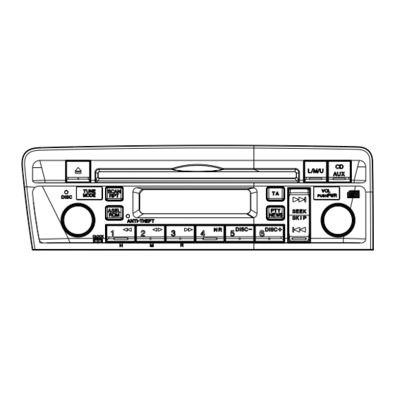
Page 59: Operations And Specifications
DEH-M6106ZH,M6106ZH-02 8. OPERATIONS AND SPECIFICATIONS 8.1 OPERATIONS - RADIO TRAFFIC ANNOUNCEMENT PTY,NEWS AUTO SELECT(U1,U2 BAND) BAND SEEK DOWN UP SCAN CLOCK PRESET MEMORY TUNING SEEK POWER ON/OFF VOLUME - CD REPEAT EJECT DOWN UP CLOCK RANDOM PLAY TRACK POWER ON/OFF VOLUME... - Page 60 DEH-M6106ZH,M6106ZH-02 - BUS (TAPE,CD-P,CD-M,MD-P,MD-M,TV) REPEAT SOURCE SELECT DOWN UP CLOCK DOWN UP RANDOM PLAY DISC SELECT TRACK POWER ON/OFF VOLUME...
-
Page 61: Specifications
DEH-M6106ZH,M6106ZH-02 8.2 SPECIFICATIONS General FM tuner Power source....13.2 V(10.8V—16.0V allowable) Frequency range......87.5 — 108.0 MHz Electrode dark current .