Sign In
Upload
Manuals
Brands
ABB Manuals
Measuring Instruments
CEMcaptain GAA610-M
ABB CEMcaptain GAA610-M Manuals
Manuals and User Guides for ABB CEMcaptain GAA610-M. We have
1
ABB CEMcaptain GAA610-M manual available for free PDF download: Operating Instruction
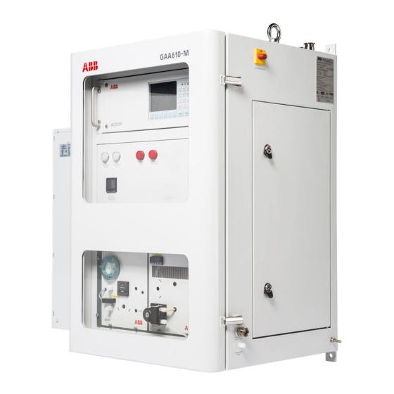
ABB CEMcaptain GAA610-M Operating Instruction (100 pages)
Advanced emission gas monitoring system for marine applications
Brand:
ABB
| Category:
Measuring Instruments
| Size: 11.47 MB
Table of Contents
Table of Contents
2
Safety
5
General Information and Instructions
5
Warnings
5
Warranty Provisions
5
Intended Use
6
Improper Use
6
Safety Instructions
6
Requirements for Safe Operation
6
Personnel Qualifications
6
Special Information and Precautions
6
National Regulations
6
Safety of the Equipment and Safe Operation
6
Working with Hazardous Gases
7
Protective Lead Connection
7
Risks Involved in Opening the Covers
7
When Safe Operation Can no Longer be Assured
7
Risks Involved in Opening the Gas Paths
7
Notes on Data Safety
7
Services and Ports on the Ethernet Interface
7
Access Authorizations
7
Manufacturer's Address
8
Service Address
8
Design and Function
9
Measuring Principle
9
Device Description
9
Type Approvals
9
Measurement Ranges
10
Inputs and Outputs
10
Analog Output
10
Digital Output
10
System Structure
11
System Cabinet
11
System Schematic
12
Sample Gas Cooler SCC-C
13
Sample Gas Feed Unit SCC-F
14
Product Identification
15
Name Plate
15
Plates and Symbols
15
Scope of Delivery
15
Transport and Storage
16
Safety Instructions
16
Inspection
16
Transporting the Device
16
Transporting the Analyzer Cabinet
16
Unpacking the Analyzer Cabinet
16
Storing the Device
17
Ambient Conditions
17
Packaging
17
Returning Devices
17
Preparation for Installation
18
Safety Instructions
18
Installation - Overview
18
Requirements for the Installation Site
18
Choosing the Extraction Point
18
Wall Tube Installation
18
Short Gas Paths
19
Protection from Adverse Ambient Conditions
19
Installation Indoors
19
Dimensions and Space Requirement
19
Installation Site Stability
19
Climatic Conditions
19
Backpurging Unit
20
Design of the Back-Purging Unit
20
Distance to Sampling Probe
20
Protection from Adverse Ambient Conditions
20
Instrument Air Supply
20
Power Supply
20
Sample Gas Inlet Conditions
20
Dimensions
21
Analyzer Cabinet
21
Type 40 Probe Tube and Filter Unit
22
Backpurging Unit
23
Material Required for Installation
24
Gas Sampling
24
Gas Lines
24
Mounting Material
24
Cable Specification
24
Installation
25
Probe Tube and Filter Unit Installation
25
Before the Installation
25
Filter Unit Overview
25
Installation
26
Sample Gas Line Installation
27
Installing the Sample Gas Line
27
Fundamentals for Laying the Sample Gas Line
27
Procedures for Laying the Sample Gas Line
28
Permissible Values for Laying the Sample Gas Line
29
Back-Purging Unit Installation
29
Before the Installation
29
Installation Site
29
Connecting the Compressed-Air Tubes
29
Analyzer Cabinet Installation
30
Transporting the Analyzer Cabinet
30
Unpacking the Analyzer Cabinet
30
Mounting the Analyzer Cabinet
30
Connecting the Condensate Water Drain of the Cabinet Air Conditioner
30
Gas Connections
31
Position and Design of the Gas Connections
31
Connecting the Gas Lines
32
Connecting the Heated Sample Gas Line
32
Calibration Gas
32
Connecting the Condensate Bottle
32
Connecting the Sample Gas Outlet
32
Electrical Connections
33
Safety Instructions
33
Protective Lead Connection
33
Notes
33
Cable Specification
33
Cable Glands
34
Terminal Assignment - Analyzer Cabinet
35
Electrical Data
37
Connecting the Electrical Leads
38
Connecting the Signal Leads
38
Connecting the Power Supply
38
Terminal Assignment - Sample Gas Probe
39
Electrical Data
39
Electrical Connection
39
Digital Communication
39
Modbus® Communication
39
Ethernet Communication
39
Gas Sampling with Automatic Back-Purging
40
General
40
Filter Plugging
40
Pump Suction Increase
40
Filter Cleaning
40
Components for Back-Purging
40
Control of the Back-Purging Procedure
40
Start of the Back-Purging Procedure
40
Start Controlled by Time
40
Start Controlled by Event
40
Filter Unit Backpurging Sequence
41
Switch over
41
Cycle Time
42
Cycle Time Duration
42
Cycle Time Factory Setting
42
Optimum Cycle Time Setting
42
Cycle Time Minimum Value
42
Event-Controlled Start of the Back-Purging Procedure by Filter Plugging
42
Adjustment of the Cycle Time
42
Post-Purge Time
42
Post-Purge Time Duration
42
Guide for the Post-Purge Time
42
10 Commissioning and Operation
43
Safety Instructions
43
When Safe Operation Can no Longer be Assured
43
Transportation Restraints Removal
43
Sample Gas Feed Unit SCC-F
43
Sample Gas Cooler SCC-C
43
Analyzer Cabinet Air Conditioner
44
Overload Protection
44
Principles of Operation
44
Start-Up
44
Prior to Start-Up
44
Power Supply Activation
44
Function Check
44
Date and Time Check
44
Warm-Up Phase
45
End of the Warm-Up Phase
45
Readiness, Sample Gas Supply
45
Calibration
45
11 Operation
46
General
46
HMI Priority
46
Access Lock
46
LCD Indicator
47
Menu Levels of the LCD Indicator
47
LCD Display
47
Display of Status Messages
48
Status Leds
48
Numeric Keypad
49
Cancel Keys
49
Softkeys
49
Entering Text
50
Selecting and Changing Parameters
51
Value Input
51
Key Entry
52
Password Protection
53
Password Level
53
User Group
53
Password
53
Viewing Menu Items
54
Changing Menu Items
54
Change Privilege
54
Change Password
54
Menu Structure
55
Basic Setup
57
Setting the Time Zone, Date and Time
57
Selecting User Interface Language
57
12 Diagnosis / Troubleshooting
58
Safety Instructions
58
The Dynamic QR Code
58
Application
58
Handling
58
Dynamic QR-Code Accessing
58
Status Messages
59
Information Available as Digital Output
59
Information Displayed on the Analyzer System
59
Possible Status Messages
59
Status Messages" Table
59
SCC-C - Sample Gas Cooler Problems
66
SCC-F - Sample Gas Feed Unit Problems
67
AO2020 Gas Analyzer Problems
67
AO2020-Uras26 Problems
68
Analyzer Cabinet Problems
68
Analyzer Cabinet Air Conditioner Problems
69
Notify Service
70
Who Should You Contact for Further Help
70
Before You Notify Service
70
If the Service Dept. Has Been Informed
70
Returning Devices
70
13 Maintenance
71
Safety Instructions
71
Maintenance Plan
72
Spare Parts
72
Spare Parts Information
72
Analyzer Cabinet - Visual Inspection
73
Visual Inspection
73
Cleaning Hints
73
Status Leds
73
Calibrating the Analyzer System
74
Conversion of Concentration Values
74
Basics
74
Calibration - Principles
74
Automatic Calibration
75
Manual Calibration
76
Basic Calibration
77
Measurement of Calibration Cells with Test Gas
78
Checking the Seal Integrity
78
When Is the Seal Integrity Check Needed
78
Procedure
78
Replacing the Filter Element in the Filter Unit
79
Soot Filter
81
Changing of the Filter Filling and the Filter Element
81
Aqua Stop Filter
82
Changing the Aqua Stop Filter
82
Ambient Air Filter (Zero Gas)
82
Changing the Ambient Air Filter
82
Analyzer Air Conditioner
83
Compressor
83
Inlet Air Filter
83
Emptying the Condensate Collection Bottle
83
SCC-C - Replace Peristaltic Pump Hose
84
SCC-C - Clean Condenser Fins
85
When Should the Condenser Fins be Cleaned
85
SCC-F - Replacing the Diaphragm and Valve Plates
86
Replacing the SCC-C
88
Remove the Old SCC-C
88
Prepare the New SCC-C
89
Install the New SCC-C
89
Replacing the SCC-F
90
Remove the Old SCC-F
90
Prepare the New SCC-F
91
Install the New SCC-F
92
Replacing the AO2020
92
Remove the Old AO2020
92
Prepare the New AO2020
93
Install the New AO2020
93
14 Decommissioning
94
Safety Instructions
94
Shutting down the Analyzer System
94
Emptying the Condensate Collecting Bottle
94
Transportation Restraints Activation
94
Sample Gas Feed Unit SCC-F
94
Sample Gas Cooler SCC-C
94
Ambient Conditions
94
15 Recycling and Disposal
95
16 Specification
95
17 Additional Documents
95
18 Appendix
96
Fuses Type 5×20Mm
96
Location Diagram
97
Piping Diagram
98
Return Form
99
Advertisement
Advertisement
Related Products
ABB GAA330-M
ABB ICOS GLA431-MCIA
ABB GLA133 Series
ABB ICOS GLA151 Series
ABB GLA451
ABB GLA451-N2OI2
ABB GLA451-N2OI3
ABB LGR GLA351-CCIA3
ABB LGR GLA351-N2OM1
ABB OA-ICOS GLA132-CCIA2
ABB Categories
Industrial Equipment
Controller
Measuring Instruments
Battery Charger
DC Drives
More ABB Manuals
Login
Sign In
OR
Sign in with Facebook
Sign in with Google
Upload manual
Upload from disk
Upload from URL