Table of Contents
Advertisement
Quick Links
—
A B B M EA S U R E M E N T & A N A L Y T I C S | O P E R A T I N G I N S T R U C T I O N | O I / G A A 6 1 0 - M - E N R E V . B
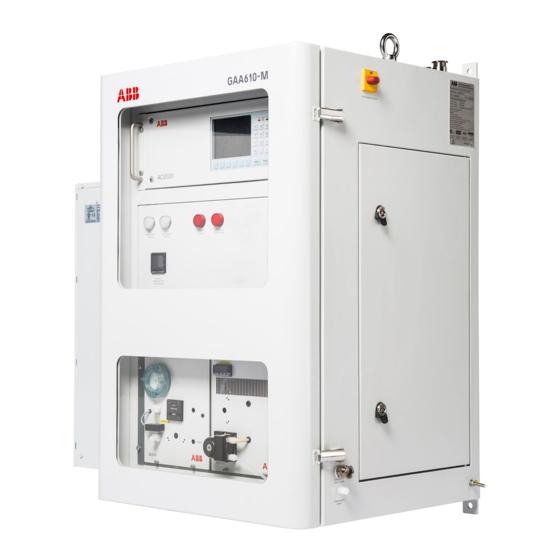
CEMcaptain GAA610-M
Advanced emission gas monitoring system for marine
applications
—
Introduction
GAA610-M
GAA610-M is a multi-component analyzer system
continuously monitoring SO2/CO2 emissions of
vessels.
Reducing maintenance hassles during ship
operation has been the guiding principle for
development. An increased uptime is provided
with the GAA610-M by its robust and simple
design as well as its innovative digital features
allowing for tailoring services to your needs.
It is proven for use on board by all major
classification societies and complies with Marpol
Annex IV requirements and NOx Technical Code
2008.
ABB has the right gas analyzer to allow vessels to
stay compliant with current and upcoming
regulations.
Measurement made easy
Additional Information
Additional documentation on CEMcaptain GAA610-M
is available for download free of charge at
www.abb.com/analytical.
Alternatively simply scan this code:
Advertisement
Table of Contents

Related Manuals for ABB CEMcaptain GAA610-M


Summary of Contents for ABB CEMcaptain GAA610-M
- Page 1 It is proven for use on board by all major classification societies and complies with Marpol Annex IV requirements and NOx Technical Code 2008. ABB has the right gas analyzer to allow vessels to stay compliant with current and upcoming regulations.
-
Page 2: Table Of Contents
GAA610-M ADVANCED EMISSION GAS MONITORING SYSTEM | OI/GAA610-M-EN REV. B Table of contents Preparation for Installation ........18 Safety ................ 5 Safety instructions ...............18 General information and instructions ......... 5 Installation – Overview ............18 Warnings .................. 5 Requirements for the installation site .......18 Warranty provisions ............... - Page 3 GAA610-M ADVANCED EMISSION GAS MONITORING SYSTEM | OI/GAA610-M-EN REV. B Gas connections ............31 10 Commissioning and operation ......43 Position and design of the gas connections ....31 Safety instructions .............. 43 Connecting the gas lines ............. 32 When safe operation can no longer be assured ..43 Connecting the heated sample gas line .......
- Page 4 GAA610-M ADVANCED EMISSION GAS MONITORING SYSTEM | OI/GAA610-M-EN REV. B 12 Diagnosis / Troubleshooting ........ 58 When should the condenser fins be cleaned? ..... 85 Safety instructions ...............58 SCC-F – Replacing the diaphragm and valve plates ..86 The Dynamic QR Code............58 Replacing the SCC-C ............
-
Page 5: Safety
GAA610-M ADVANCED EMISSION GAS MONITORING SYSTEM | OI/GAA610-M-EN REV. B 1 Safety General information and instructions Warnings The warnings in these instructions are structured as follows: These instructions are an important part of the product and must be retained for future reference. DANGER Installation, commissioning, and maintenance of the product may only be performed by trained specialist personnel who have... -
Page 6: Intended Use
Safety instructions Intended use Requirements for safe operation The CEMcaptain GAA610-M analyzer system is designed for In order to operate in a safe and efficient manner the device continuous measurement of exhaust gases of marine diesel should be properly handled and stored, correctly installed and engines. -
Page 7: Working With Hazardous Gases
Ensure adequate ventilation of the room in which the leakage and / or theft of data or information. analyzer system is installed. ABB Ltd and its affiliates are not liable for damages and / or • The legal requirements for the maximum work place limit losses related to such security breaches, any unauthorized values of the measurement and test gases must be observed. -
Page 8: Manufacturer's Address
Fax: +86(0) 21 6105 6677 Email: china.instrumentation@cn.abb.com Service address If the information in this Operating Instruction does not cover a particular situation, ABB Service will be pleased to supply additional information as required. Please contact your local service representative. For emergencies, please contact: Contact Center www.abb.com/contacts... -
Page 9: Design And Function
GAA610-M ADVANCED EMISSION GAS MONITORING SYSTEM | OI/GAA610-M-EN REV. B 2 Design and function Measuring principle The GAA610-M is based on ABB’s proven NDIR (Non-Dispersive Therefore, additional devices, such as the sampling probe, the Infrared) measurement technology. sample gas line, the sample gas cooler, pumps and filters ensure... -
Page 10: Measurement Ranges
GAA610-M ADVANCED EMISSION GAS MONITORING SYSTEM | OI/GAA610-M-EN REV. B … 2 Design and function Measurement ranges Sample components and measuring ranges Sample component Standard measuring ranges 0 to 20 Vol.-% 0 to 250 ppm 0 to 500 ppm ratio Calculated (option) 0 to 25 Vol.-%... -
Page 11: System Structure
GAA610-M ADVANCED EMISSION GAS MONITORING SYSTEM | OI/GAA610-M-EN REV. B System structure System cabinet 1 Main switch 5 Ethernet port 2 Gas analyzer AO2020 6 Sample Gas Cooler SCC-C 3 Status indicators for measuring, back purge, general alarm, condensate 7 Sample Gas Feed Unit SCC-F level 8 Cabinet air conditioner 4 Heated sample gas line temperature controller... -
Page 12: System Schematic
GAA610-M ADVANCED EMISSION GAS MONITORING SYSTEM | OI/GAA610-M-EN REV. B … 2 Design and function … System structure System schematic A Exhaust gas stream D Ambient air / zero gas inlet B Compressed instrument air inlet E Sample gas outlet C Calibration gas inlet F Condensate outlet 1 Exhaust pipe... -
Page 13: Sample Gas Cooler Scc-C
GAA610-M ADVANCED EMISSION GAS MONITORING SYSTEM | OI/GAA610-M-EN REV. B Sample Gas Cooler SCC-C Heated sample gas line The heated sample gas line is directly connected to the filter at the probe. The core is a PTFE hose. The line is heated to 180 °C (356 °F). -
Page 14: Sample Gas Feed Unit Scc-F
GAA610-M ADVANCED EMISSION GAS MONITORING SYSTEM | OI/GAA610-M-EN REV. B … 2 Design and function … System structure Sample Gas Feed Unit SCC-F 1 Condensate monitor 3 Flow monitor with needle valve 2 LED display and reset switch for condensate and flow alarm Figure 4: Sample Gas Feed Unit SCC-F The sample gas feed unit sucks the sample from the exhaust gas and continuously feeds the gas analyzer with the sample gas. -
Page 15: Product Identification
GAA610-M ADVANCED EMISSION GAS MONITORING SYSTEM | OI/GAA610-M-EN REV. B 3 Product identification Name plate Plates and symbols Note The following labels and symbols are attached to the analyzer system or to the individual components. The name plates displayed are examples. The device identification plates affixed to the device can differ from this representation. -
Page 16: Transport And Storage
GAA610-M ADVANCED EMISSION GAS MONITORING SYSTEM | OI/GAA610-M-EN REV. B 4 Transport and storage Transporting the device Safety instructions CAUTION Transporting the analyzer cabinet NOTICE Injury hazard due to heavy weight Depending on the version, the gas analyzer cabinet weighs Potential damage to the device! approx. -
Page 17: Storing The Device
All devices delivered to ABB must be free from any hazardous materials (acids, alkalis, solvents, etc.). Address for the return: Contact Center www.abb.com/contacts... -
Page 18: Preparation For Installation
Note inspection authority, e.g. classification society. • The system must be installed by ABB or by personnel trained by ABB. Wall tube installation • When installing the analyzer system, in addition to this operating instruction, comply with the information contained in the drawings set. -
Page 19: Short Gas Paths
GAA610-M ADVANCED EMISSION GAS MONITORING SYSTEM | OI/GAA610-M-EN REV. B Short gas paths Climatic Conditions The analyzer cabinet should be installed as close as possible to Ambient temperature the sampling site. A short sample gas line results in short T In operation: 5 to 55 °C* (41 to 131 °F)* times. -
Page 20: Backpurging Unit
GAA610-M ADVANCED EMISSION GAS MONITORING SYSTEM | OI/GAA610-M-EN REV. B … 5 Preparation for Installation Backpurging Unit Power supply Design of the back-purging unit Power supply The back-purging unit consists of a protective cabinet with shut- Terminals -X60: L, N, PE or L1, L2, PE off valve, 6 bar pressure reduction valve, solenoid valves for Operating voltage 230 V AC, ±10 %... -
Page 21: Dimensions
GAA610-M ADVANCED EMISSION GAS MONITORING SYSTEM | OI/GAA610-M-EN REV. B Dimensions Analyzer cabinet 1 Vibration damper 3 Maintenance area 2 Mounting plate for vibration dampers Figure 8: Dimensions analyzer cabinet, mm (in) Weight of the individual system components Component Weight Analyzer cabinet 240 kg (441 lb), depending on configuration Probe tube type 40... -
Page 22: Type 40 Probe Tube And Filter Unit
GAA610-M ADVANCED EMISSION GAS MONITORING SYSTEM | OI/GAA610-M-EN REV. B … 5 Preparation for Installation … Dimensions Type 40 probe tube and filter unit A Type 40 probe tube B Heated filter unit 1 Backpurging air inlet from solenoid valve S0V2 4 Cable gland for heated filter unit power supply 2 Backpurging air inlet from solenoid valve S0V1 5 Cable gland for heated filter unit alarm signal... -
Page 23: Backpurging Unit
GAA610-M ADVANCED EMISSION GAS MONITORING SYSTEM | OI/GAA610-M-EN REV. B Backpurging Unit A Backpurging panel B Filter unit 1 Pressure regulator 4 Backpurging solenoid valve SOV2 2 Instrument air inlet, 10 mm O.D. Tube fitting for stainless steel pipe 5 Backpurging solenoid valve SOV1 3 Pressure buffer tank 6 Stainless steel pipe 10 mm O.D., to be intalled by customer Figure 10: Backpurging panel... -
Page 24: Material Required For Installation
GAA610-M ADVANCED EMISSION GAS MONITORING SYSTEM | OI/GAA610-M-EN REV. B … 5 Preparation for Installation Material required for installation Note Cable specification The materials listed below are not included in the scope of Note delivery of the device, and must be provided by the customer. All cables entering the system must comply with the flammability class VW1, FT1 or EN60332-1-2/-2-2. -
Page 25: Installation
GAA610-M ADVANCED EMISSION GAS MONITORING SYSTEM | OI/GAA610-M-EN REV. B 6 Installation Probe tube and filter unit installation CAUTION Injury hazard due to heavy weight The weight of the probe tube with filter unit amounts to approx. 18 to 20 kg! •... -
Page 26: Installation
GAA610-M ADVANCED EMISSION GAS MONITORING SYSTEM | OI/GAA610-M-EN REV. B … 6 Installation … Probe tube and filter unit installation Installation Flange orientation Filter unit 1 Duct wall 5 Filter Unit 2 Flange 6 Probe tube 3 Flange gasket 7 Flow direction 4 Probe flange 8 Sample gas inlet Figure 12: Filter unit installation... -
Page 27: Sample Gas Line Installation
GAA610-M ADVANCED EMISSION GAS MONITORING SYSTEM | OI/GAA610-M-EN REV. B Sample gas line installation Installing the sample gas line • Observe the "Piping plan" in the drawings set. Connection of the heated sample gas line • Connect the sample gas line to the filter unit/gas sampling probe. -
Page 28: Procedures For Laying The Sample Gas Line
GAA610-M ADVANCED EMISSION GAS MONITORING SYSTEM | OI/GAA610-M-EN REV. B … 6 Installation … Sample gas line installation Procedures for laying the sample gas line Wall break-through Laying in ducts or shafts Incorrect Correct Incorrect Correct Figure 15: Laying in ducts or shafts Figure 18: Wall break-through Do not lay the heated sample gas lines directly side-by-side Do not lay the heated sample gas line in a wall break-through... -
Page 29: Permissible Values For Laying The Sample Gas Line
GAA610-M ADVANCED EMISSION GAS MONITORING SYSTEM | OI/GAA610-M-EN REV. B Back-purging unit installation Before the installation Mounting brackets Observe the ‘Piping plan’ in the drawings set. Incorrect Correct Installation site The distance between the back-purging unit and the sampling probe should be as short as possible and must not exceed 2 m (6.6 ft). -
Page 30: Analyzer Cabinet Installation
GAA610-M ADVANCED EMISSION GAS MONITORING SYSTEM | OI/GAA610-M-EN REV. B … 6 Installation Analyzer cabinet installation CAUTION Mounting the analyzer cabinet • Observe the installation site requirements. Injury hazard due to heavy weight • The loading capacity of the wall must be high enough to bear Depending on the version, the gas analyzer cabinet weighs the weight of the analyzer cabinet. -
Page 31: Gas Connections
GAA610-M ADVANCED EMISSION GAS MONITORING SYSTEM | OI/GAA610-M-EN REV. B 7 Gas connections Position and design of the gas connections Figure 23: Gas connections GAA610-M Pos. Connection Additional Information Design TSG2 Sample gas inlet For heated sample gas line TBL01 with outer diameter of Tube fitting 4/6 ×... -
Page 32: Connecting The Gas Lines
GAA610-M ADVANCED EMISSION GAS MONITORING SYSTEM | OI/GAA610-M-EN REV. B … 7 Gas connections Connecting the gas lines Connecting the heated sample gas line Connecting the sample gas outlet Connect the heated sample gas line as shown in system Observe the following points when connecting the exhaust air schematic Figure 2 on page 12: pipe: 1. -
Page 33: Electrical Connections
GAA610-M ADVANCED EMISSION GAS MONITORING SYSTEM | OI/GAA610-M-EN REV. B 8 Electrical connections Safety instructions Cable specification Note WARNING All cables entering the system must comply with the Risk of injury due to live parts. flammability class VW1, FT1 or EN60332-1-2/-2-2. Improper work on the electrical connections can result in electric shock. -
Page 34: Cable Glands
GAA610-M ADVANCED EMISSION GAS MONITORING SYSTEM | OI/GAA610-M-EN REV. B … 8 Electrical connections Cable glands Figure 24: Location of the cable Glands Pos. Cable Gland Usage Power supply Sample probe heater power supply Analogue signals to DCS Digital signals to/from DCS Modbus cable to DCS TS4-SOV1 Backpurge unit SOV1 power supply... -
Page 35: Terminal Assignment - Analyzer Cabinet
GAA610-M ADVANCED EMISSION GAS MONITORING SYSTEM | OI/GAA610-M-EN REV. B Terminal assignment – Analyzer cabinet 1 Power supply 7 Ethernet interface 2 Power output for heated sample gas probe 8 I/O for sample probe and backpurging 3 Power output for heated sample gas line TBL01 9 Digital input for condensate bottle level monitoring 4 Pt100 temperature sensor from heated sample gas line TBL01 0 Digital outputs... - Page 36 GAA610-M ADVANCED EMISSION GAS MONITORING SYSTEM | OI/GAA610-M-EN REV. B … 8 Electrical connections … Terminal assignment – Analyzer cabinet Figure 26: Location of the terminal strips on the back plate of the analyzer cabinet Terminal Description Terminal Description –X60 Main power supply and power out for heated sample gas probe –X63 Digital outputs / System status signals...
-
Page 37: Electrical Data
GAA610-M ADVANCED EMISSION GAS MONITORING SYSTEM | OI/GAA610-M-EN REV. B Electrical Data Power supply Backpurging unit -X60: L, N, PE or L1, L2, PE -X62 – 1, 2 Terminals Terminals Valve 1: -X62 – 3, 4 Operating voltage 230 V AC, ±10 % Valve 2: Power supply output 24 V DC... -
Page 38: Connecting The Electrical Leads
GAA610-M ADVANCED EMISSION GAS MONITORING SYSTEM | OI/GAA610-M-EN REV. B … 8 Electrical connections … Terminal assignment – Analyzer cabinet Connecting the electrical leads Connecting the power supply Observe the cable specifications, see Cable specification on • Note page 33 An easily accessible mains isolator must be installed near the •... -
Page 39: Terminal Assignment - Sample Gas Probe
GAA610-M ADVANCED EMISSION GAS MONITORING SYSTEM | OI/GAA610-M-EN REV. B Terminal assignment – Sample gas probe Digital communication Modbus® communication Transmission of measured values and status signals as well as analog input, digital input and digital output signals to host systems, e.g. standard Windows applications via M-DDE server. -
Page 40: Gas Sampling With Automatic Back-Purging
GAA610-M ADVANCED EMISSION GAS MONITORING SYSTEM | OI/GAA610-M-EN REV. B 9 Gas sampling with automatic back-purging General Components for back-purging To carry out the automatic back-purging of the filter unit, Filter plugging components are integrated in the analyzer system as follows: During operation of the analyzer system the dust which is •... -
Page 41: Filter Unit Backpurging Sequence
GAA610-M ADVANCED EMISSION GAS MONITORING SYSTEM | OI/GAA610-M-EN REV. B Filter unit backpurging sequence Step Duration Function Sample gas valve Probe tube Filter backpurging Display Status signal −Y60 backpurging valve valve −Y62 −Y61 12 h* Measuring Sample gas Closed Closed Measure Switch over Ambient air... -
Page 42: Cycle Time
To adjust the post-purge time the parameters of the AO2020 blocking occur caused by temporary larger amounts of dust, must be changed. Please contact ABB service. with the result of a sample gas flow decrease beneath the admissible limit, an additional back-purging procedure is started as a result, and the probe filter is purged free in between. -
Page 43: 10 Commissioning And Operation
Note Initial startup of the analyzer system should be performed by trained personnel of the manufacturer or the supplier. ABB recommends having the startup done by ABB personnel. When safe operation can no longer be assured 1 Sample Gas Feed Unit SCC-F transportation restraints... -
Page 44: Analyzer Cabinet Air Conditioner
GAA610-M ADVANCED EMISSION GAS MONITORING SYSTEM | OI/GAA610-M-EN REV. B … 10 Commissioning and operation Analyzer cabinet air conditioner Start-up Prior to start-up NOTICE Check analyzer system seal integrity. Damage to the air conditioner Damage to the air conditioner due to incorrect Power supply activation commissioning. -
Page 45: Warm-Up Phase
GAA610-M ADVANCED EMISSION GAS MONITORING SYSTEM | OI/GAA610-M-EN REV. B Warm-up phase The warm-up time for the system is approx. 2 to 4 hours. The warm-up phase can take longer if the analyzer system was not brought to room temperature before the power supply was activated. -
Page 46: 11 Operation
GAA610-M ADVANCED EMISSION GAS MONITORING SYSTEM | OI/GAA610-M-EN REV. B 11 Operation General Specifics for manual calibration The AO2000 series gas analyzers have several user interfaces: • The local operation user interface is the display and Manual calibration runs at level 0, thus no password is needed. control unit on the gas analyzer (‘local HMI’). -
Page 47: Lcd Indicator
GAA610-M ADVANCED EMISSION GAS MONITORING SYSTEM | OI/GAA610-M-EN REV. B LCD indicator LCD display The backlit graphics has a 320 x 240-pixel resolution. The screen is divided into three panels: • Menu line • Information field • Softkey line The menu line The menu line appears at the upper edge of the screen. -
Page 48: Display Of Status Messages
GAA610-M ADVANCED EMISSION GAS MONITORING SYSTEM | OI/GAA610-M-EN REV. B … 11 Operation … LCD indicator Display of status messages In addition, the user can configure display elements that allow The softkey line also displays messages from the gas analyzer. •... -
Page 49: Numeric Keypad
GAA610-M ADVANCED EMISSION GAS MONITORING SYSTEM | OI/GAA610-M-EN REV. B Numeric keypad Softkeys The numeric keypad is located to the right of the screen, under The six buttons under the screen and the softkey line at the the status LED’s. lower edge of the screen are known as softkeys. -
Page 50: Entering Text
GAA610-M ADVANCED EMISSION GAS MONITORING SYSTEM | OI/GAA610-M-EN REV. B … 11 Operation … LCD indicator The Softkeys in Menu Mode Entering text In menu mode, a series of softkeys appears on the softkey line, When text, such as sample components or user names, needs to whose labeling and therefore function change based on the be entered an ‘image’... -
Page 51: Selecting And Changing Parameters
GAA610-M ADVANCED EMISSION GAS MONITORING SYSTEM | OI/GAA610-M-EN REV. B Selecting and changing parameters Value Input Numeric and alphanumeric parameter values can be entered directly via the keyboard using the value input. Numbers on the keyboard are assigned to the individual parameters;... -
Page 52: Key Entry
GAA610-M ADVANCED EMISSION GAS MONITORING SYSTEM | OI/GAA610-M-EN REV. B … 11 Operation … Selecting and changing parameters Key Entry • The LCD display will now display an entry field to change the Using the key entry, preset parameter values can be selected parameter value. -
Page 53: Password Protection
GAA610-M ADVANCED EMISSION GAS MONITORING SYSTEM | OI/GAA610-M-EN REV. B Password protection Password protection consists of three elements: • Password level, • The LCD display now shows the softkeys for selecting the • User group and parameters for changing the parameter value. •... -
Page 54: Viewing Menu Items
GAA610-M ADVANCED EMISSION GAS MONITORING SYSTEM | OI/GAA610-M-EN REV. B … 11 Operation … Password protection Factory setting Duration of the change privilege Passwords are pre-assigned for the factory-set user groups. The change privilege remains in place until • either the gas analyzer automatically switches to measuring mode if the user does not actuate a button for about five minutes (‘time-out’), User Group... -
Page 55: Menu Structure
GAA610-M ADVANCED EMISSION GAS MONITORING SYSTEM | OI/GAA610-M-EN REV. B Menu structure Note For a detailed description of the individual parameters and menus, please refer to the chapter ‘Configuration’ in the operating instruction OI/AO2000. For reasons of brevity only the top-level parameters and functions are shown; the menu branches more extensively at most menu items, e.g. - Page 56 GAA610-M ADVANCED EMISSION GAS MONITORING SYSTEM | OI/GAA610-M-EN REV. B … 11 Operation … Menu structure...
-
Page 57: Basic Setup
GAA610-M ADVANCED EMISSION GAS MONITORING SYSTEM | OI/GAA610-M-EN REV. B Basic Setup Setting the time zone, date and time Selecting user interface language Menu path Menu path ‘MENU / Configure / System / Date/Time’ ‘MENU / Configure / System / Language’ Procedure Language selection Two user interface languages are factory-configured (per order) -
Page 58: 12 Diagnosis / Troubleshooting
Google Play This helps to shorten response times in the event of a fault, thereby increasing the availability of your gas analyzers. Dynamic QR Code is compatible with both the ABB app “my Installed Base” and standard QR Code scanner apps... -
Page 59: Status Messages
GAA610-M ADVANCED EMISSION GAS MONITORING SYSTEM | OI/GAA610-M-EN REV. B Status messages Information available as digital output Information displayed on the analyzer system • System Failure • Maintenance Mode • Maintenance • Watchdog signal error (Communication error) • Maintenance Request •... - Page 60 GAA610-M ADVANCED EMISSION GAS MONITORING SYSTEM | OI/GAA610-M-EN REV. B … 12 Diagnosis / Troubleshooting … Possible status messages Text Reaction/Remark The Profibus Module is mounted on the wrong See message text slot! The Profibus interface is therefore not working. Please remount the Profibus Module on slot X20/X21.
- Page 61 GAA610-M ADVANCED EMISSION GAS MONITORING SYSTEM | OI/GAA610-M-EN REV. B Text Reaction/Remark Analyzer modules No new measured values from the analog/digital Notify Service. converter. The measured value exceeds the range of the Check the sample gas concentration. Notify Service. analog/digital converter. Offset drift exceeds half the permissible range.
- Page 62 GAA610-M ADVANCED EMISSION GAS MONITORING SYSTEM | OI/GAA610-M-EN REV. B … 12 Diagnosis / Troubleshooting … Possible status messages Text Reaction/Remark Uras No new measured values from the analog/digital Notify Service. converter. Temperature regulator Temperature is above or below upper and/or Status messages during the warm-up phase.
- Page 63 GAA610-M ADVANCED EMISSION GAS MONITORING SYSTEM | OI/GAA610-M-EN REV. B Text Reaction/Remark Flow monitor (pneumatic module) The flow rate undershoots limit value 1 Check sample preparation. Alarm value 1 = 25 % of MRS. Flow rate undershoots limit value 2. Check sample preparation.
- Page 64 GAA610-M ADVANCED EMISSION GAS MONITORING SYSTEM | OI/GAA610-M-EN REV. B … 12 Diagnosis / Troubleshooting … Possible status messages Text Reaction/Remark Calibration (continuation) Unknown error number. Check software versions. Message during the automatic calibration. Check analyzer module and system controller software versions. Automatic calibration started.
- Page 65 GAA610-M ADVANCED EMISSION GAS MONITORING SYSTEM | OI/GAA610-M-EN REV. B Text Reaction/Remark User-Configured Messages An external error occurred during: Default texts for the Message Generator function block are supplemented with the full text defined during function block configuration. A user-defined error occurred during: A user-defined maintenance request occurred during A user-defined maintenance mode event...
-
Page 66: Scc-C - Sample Gas Cooler Problems
GAA610-M ADVANCED EMISSION GAS MONITORING SYSTEM | OI/GAA610-M-EN REV. B … 12 Diagnosis / Troubleshooting SCC-C – Sample gas cooler problems Problem Cause Remedy Condensate in the Sample Gas Outlet Ambient temperature < 5 °C • Heat the downstream assemblies. Sample gas cooler overloaded •... -
Page 67: Scc-F - Sample Gas Feed Unit Problems
GAA610-M ADVANCED EMISSION GAS MONITORING SYSTEM | OI/GAA610-M-EN REV. B SCC-F – Sample gas feed unit problems Problem Cause Remedy Sample Gas Feed Unit not working Power supply interrupted Reconnect the power supply. Fuse blown Replace fuse (2 A T). Pump motor blocked Replace SCC-F unit or consult service contact. -
Page 68: Ao2020-Uras26 Problems
GAA610-M ADVANCED EMISSION GAS MONITORING SYSTEM | OI/GAA610-M-EN REV. B … 12 Diagnosis / Troubleshooting AO2020-Uras26 problems Problem Cause Remedy Temperature Problem Faulty temperature sensor or heater Check the connecting lines and plugs. connections Check the line seating in the insulated jackets. Defective thermal link Check thermal link continuity and replace if necessary. -
Page 69: Analyzer Cabinet Air Conditioner Problems
GAA610-M ADVANCED EMISSION GAS MONITORING SYSTEM | OI/GAA610-M-EN REV. B Analyzer cabinet air conditioner problems Problem Cause Remedy Clean fins and filter, see Cleaning and changing the inlet air filter on Unit won’t cool • Clogged fins on coil(s) • •... -
Page 70: Notify Service
For more information visit: www.abb.com/measurement purposes: All devices delivered to ABB must be free from any hazardous materials (acids, alkalis, solvents, etc.). Before you notify Service … Address for the return:... -
Page 71: 13 Maintenance
GAA610-M ADVANCED EMISSION GAS MONITORING SYSTEM | OI/GAA610-M-EN REV. B 13 Maintenance Safety instructions WARNING Risk of injury Risk of injury due to maintenance work being carried out incorrectly. The work described in this chapter require special knowledge and may require work to be done on the gas analyzer while it is open and under voltage! •... -
Page 72: Maintenance Plan
Flexible tube set for sample gas cooler SCC-C 2× 90P1007 Spare parts set for sample gas feed unit SCC-F 8018551 Aqua stop filter 8018512 Ambient air filter (Zero gas filter) 768322 Spare parts information Spare parts information can be found on the Internet using the address www.online.abb.com. -
Page 73: Analyzer Cabinet - Visual Inspection
GAA610-M ADVANCED EMISSION GAS MONITORING SYSTEM | OI/GAA610-M-EN REV. B Analyzer cabinet – Visual inspection Status LEDs The three LEDs next to the screen show the user the gas analyzer’s status. Status LED Description The green ‘Power’ LED lights when the power supply is on. The yellow ‘Maint’... -
Page 74: Calibrating The Analyzer System
GAA610-M ADVANCED EMISSION GAS MONITORING SYSTEM | OI/GAA610-M-EN REV. B … 13 Maintenance Calibrating the analyzer system Calibration – Principles Notice Preconditions Impairment of the analyzer function • Ambient air temperature: 5 °C to 40 °C Impairment of the analyzer function due to improper •... -
Page 75: Automatic Calibration
GAA610-M ADVANCED EMISSION GAS MONITORING SYSTEM | OI/GAA610-M-EN REV. B Automatic calibration Definition Automatic calibration means: When you reach the control page, you can start the calibration by Calibration with internal gas filled cells and ambient air. Zero and pressing key 6. You can also deactivate the automatic calibration span calibration run automatically after starting. -
Page 76: Manual Calibration
GAA610-M ADVANCED EMISSION GAS MONITORING SYSTEM | OI/GAA610-M-EN REV. B … 13 Maintenance … Calibrating the analyzer system Span Point Manual calibration Definition Manual calibration means: Calibration with test gases. Zero and span are calibrated separately by pressing the gas analyzer display and control unit softkeys. -
Page 77: Basic Calibration
GAA610-M ADVANCED EMISSION GAS MONITORING SYSTEM | OI/GAA610-M-EN REV. B Basic calibration What does the basic calibration do? Pressure Sensor Calibration A basic calibration of an analyzer module sets the module back in The pressure sensor calibration can be performed at ‘MENU / an initial state. -
Page 78: Measurement Of Calibration Cells With Test Gas
GAA610-M ADVANCED EMISSION GAS MONITORING SYSTEM | OI/GAA610-M-EN REV. B … 13 Maintenance … Calibrating the analyzer system Checking the seal integrity When is the seal integrity check needed? Measurement of calibration cells with test gas Complete seal integrity check of the analyzer system is reserved Definition for certified service personnel. -
Page 79: Replacing The Filter Element In The Filter Unit
GAA610-M ADVANCED EMISSION GAS MONITORING SYSTEM | OI/GAA610-M-EN REV. B Replacing the filter element in the filter unit CAUTION Danger of burns Danger of burns on the hot measuring probe. • Switch off the power supply to the probe heater. •... - Page 80 GAA610-M ADVANCED EMISSION GAS MONITORING SYSTEM | OI/GAA610-M-EN REV. B … 13 Maintenance … Replacing the filter element in the filter unit 9. Attach the new filter element and tighten it hand-tight with the filter holding screw. NOTICE Damage to the filter element Damage to the filter element due to improper installation.
-
Page 81: Soot Filter
GAA610-M ADVANCED EMISSION GAS MONITORING SYSTEM | OI/GAA610-M-EN REV. B Soot filter 9. Screw the new filter element into the filter housing and seal the upper opening. 1 Raschig rings 3 Filter element 2 Seal 4 Filter housing Figure 47: Replace filter element 10. -
Page 82: Aqua Stop Filter
GAA610-M ADVANCED EMISSION GAS MONITORING SYSTEM | OI/GAA610-M-EN REV. B … 13 Maintenance Aqua stop filter Ambient air filter (zero gas) A Sample gas inlet from SCC-F B Sample gas outlet to AO2020 1 Aqua stop filter 1 Ambient air filter Figure 48: Aqua stop filter Figure 49: Ambient air filter The aqua stop filter is located behind the right door of the... -
Page 83: Analyzer Air Conditioner
GAA610-M ADVANCED EMISSION GAS MONITORING SYSTEM | OI/GAA610-M-EN REV. B Analyzer air conditioner Compressor Cleaning and changing the inlet air filter The compressor requires no maintenance. It is hermetically Aluminum washable air filters are designed to provide excellent sealed, properly lubricated at the factory and should provide filtering efficiency with a high dust holding capacity and a years of satisfactory operating service. -
Page 84: Scc-C - Replace Peristaltic Pump Hose
GAA610-M ADVANCED EMISSION GAS MONITORING SYSTEM | OI/GAA610-M-EN REV. B … 13 Maintenance SCC-C – Replace peristaltic pump hose CAUTION Remove the old hose: 3. Remove the hoses from the hose connections Risk of injury due to corrosive condensates 4. Using the handles, press the moving belt together and Condensates are often corrosive. -
Page 85: Scc-C - Clean Condenser Fins
GAA610-M ADVANCED EMISSION GAS MONITORING SYSTEM | OI/GAA610-M-EN REV. B SCC-C – Clean condenser fins When should the condenser fins be cleaned? 7. Press the cable lug of the protective leads onto the quick Cooling performance is reduced by the accumulation of dust on terminal on the inside of the covering hood, put the covering the condenser fins. -
Page 86: Scc-F - Replacing The Diaphragm And Valve Plates
GAA610-M ADVANCED EMISSION GAS MONITORING SYSTEM | OI/GAA610-M-EN REV. B … 13 Maintenance SCC-F – Replacing the diaphragm and valve plates When do the diaphragm and valve plates need to be replaced? The diaphragm and valve plates in the diaphragm pump must be 1. - Page 87 GAA610-M ADVANCED EMISSION GAS MONITORING SYSTEM | OI/GAA610-M-EN REV. B Reinstall diaphragm pumps: 27. Connect pump hoses. 11. Push the distance ring(s) and the Belleville spring in that 28. Insert mounting plate with the pumps into the sample gas order onto the threaded bolt of the new structural feed unit’s casing and fasten it with the two hex socket head diaphragm.
-
Page 88: Replacing The Scc-C
GAA610-M ADVANCED EMISSION GAS MONITORING SYSTEM | OI/GAA610-M-EN REV. B … 13 Maintenance Replacing the SCC-C Remove the old SCC-C If there is a malfunction of the SCC-C, it may be necessary to replace it. In the following, the individual points are described step by step. -
Page 89: Prepare The New Scc-C
GAA610-M ADVANCED EMISSION GAS MONITORING SYSTEM | OI/GAA610-M-EN REV. B Prepare the new SCC-C Install the new SCC-C 1. Insert the prepared SCC-C into the housing of the GAA610-M. 2. Put the cables through the cable inlets of the SCC-C and connect them. -
Page 90: Replacing The Scc-F
GAA610-M ADVANCED EMISSION GAS MONITORING SYSTEM | OI/GAA610-M-EN REV. B … 13 Maintenance Replacing the SCC-F If there is a malfunction of the SCC-F, it may be necessary to Remove the old SCC-F replace it. In the following, the individual points are described step by step. -
Page 91: Prepare The New Scc-F
GAA610-M ADVANCED EMISSION GAS MONITORING SYSTEM | OI/GAA610-M-EN REV. B Figure 57: Electrical connections SCC-F 8. When the cover is removed and the power is disconnected, you can remove the marked connectors . Pay attention to the PE on the connection plate. All connections to the SCC-F are now disconnected. -
Page 92: Install The New Scc-F
GAA610-M ADVANCED EMISSION GAS MONITORING SYSTEM | OI/GAA610-M-EN REV. B … 13 Maintenance … Replacing the SCC-F Replacing the AO2020 If there is a malfunction of the AO2020, it may be necessary to Install the new SCC-F replace it. In the following, the individual points are described 1. -
Page 93: Prepare The New Ao2020
GAA610-M ADVANCED EMISSION GAS MONITORING SYSTEM | OI/GAA610-M-EN REV. B Prepare the new AO2020 The new AO2020 is calibrated and ready for use. Only the gas connections need to be screwed into the connection plate. Make sure that the connections are gas tight. Install the new AO2020 1. -
Page 94: 14 Decommissioning
GAA610-M ADVANCED EMISSION GAS MONITORING SYSTEM | OI/GAA610-M-EN REV. B 14 Decommissioning Safety instructions Transportation restraints activation CAUTION Risk of injury due to corrosive condensates Condensates are often corrosive. • When working with corrosive reagents note the hazard information and safety precautions contained in the applicable material safety data sheets. -
Page 95: 15 Recycling And Disposal
16 Specification Note Note Products that are marked with the adjacent symbol The device data sheet is available in the ABB download area at may not be disposed of as unsorted municipal waste www.abb.com/analytical. (domestic waste). They should be disposed of through separate 17 Additional documents collection of electric and electronic devices. -
Page 96: 18 Appendix
GAA610-M ADVANCED EMISSION GAS MONITORING SYSTEM | OI/GAA610-M-EN REV. B 18 Appendix Fuses type 5×20mm Marking Function Tripping characteristic Tripping current -F70 Fuse protection 24V DC control emergency shutdown system (-K60, -S60) time-lag fuse -F71 Fuse protection 24V DC control of sample gas valve (-Y60) time-lag fuse -F72 Fuse protection 24V DC control of blowback valves (-Y61,-Y62) -
Page 97: Location Diagram
GAA610-M ADVANCED EMISSION GAS MONITORING SYSTEM | OI/GAA610-M-EN REV. B Location diagram... -
Page 98: Piping Diagram
GAA610-M ADVANCED EMISSION GAS MONITORING SYSTEM | OI/GAA610-M-EN REV. B … 18 Appendix Piping diagram... -
Page 99: Return Form
GAA610-M ADVANCED EMISSION GAS MONITORING SYSTEM | OI/GAA610-M-EN REV. B Return form Statement on the contamination of devices and components Repair and/or maintenance work will only be performed on devices and components if a statement form has been completed and submitted. - Page 100 We reserve the right to make technical changes or modify the contents of this document without prior notice. With regard to purchase orders, the agreed particulars shall prevail. ABB does not accept any responsibility whatsoever for potential errors or possible lack of information in this document.