
Related Manuals for ABB GLA451


Summary of Contents for ABB GLA451
- Page 1 — ABB MEASUREMENT & ANALYTICS | USER MANUAL User Manual | ICOS GLA451 Enhanced Performance QC Benchtop Analyzers...
-
Page 2: Table Of Contents
USER MANUAL | ICOS | INSTRUCTIONS | UM/ICOS-EN REV. B.2 Table of Contents Disclaimer ........................... 5 Cybersecurity .......................... 5 Patent ............................5 Copyright ............................ 5 Safety ............................6 Class of Laser Equipment ..................... 6 Certification ..........................6 WEEE Directive ........................6 Labels ............................ - Page 3 Replace the Power Inlet Fuse ....................66 Appendix A: About Gas Analyzers and Laser Absorption Spectroscopy ....... 67 Conventional Laser Absorption Spectroscopy ..............67 ABB-LGR’s Off-Axis Integrated-Cavity Output Spectroscopy (Off-Axis ICOS) ....69 Appendix B: Accessing Data Using the Ethernet ............... 70 Appendix C:...
- Page 4 Batch Mode Operation ..................105 Appendix I: Spectrum Displays ....................115 GLA451-AAQC Enhanced Performance QC Benchtop Trace Ammonia Analyzer ..115 GLA451-N2OI2 Enhanced Performance QC Benchtop Isotopic Nitrous Oxide Analyzer ..........................116 GLA451-N2OI3 Enhanced Performance QC Benchtop Isotopic Nitrous Oxide Analyzer ...
-
Page 5: Disclaimer
ABB and its affiliates are not liable for damages and/or losses related to such security breaches, any unauthorized access, interference, intrusion, leakage and/or theft of data or information. -
Page 6: Safety
USER MANUAL | ICOS | INSTRUCTIONS | UM/ICOS-EN REV. B.2 Safety The following pages provide important safety precautions. Class of Laser Equipment The analyzer is a Class 1 laser instrument when the case cover is closed for normal operation, and the lock is installed. Certification The analyzer certifications are listed in Table 1. -
Page 7: Labels
USER MANUAL | ICOS | INSTRUCTIONS | UM/ICOS-EN REV. B.2 Labels The following labels are at specific locations on or in the analyzer to identify hazardous areas. (Figure 1) Figure 1: Radiation Labels These labels are located on the enclosure covering the ICOS cell. The fiber laser is visible only when the insulated enclosure is removed from the ICOS cell. -
Page 8: Laser Hazards
Only trained service personnel are authorized to open the housing or service the laser. Using this analyzer in a manner not specified by ABB-LGR may result in damage to the analyzer and render it unsafe to operate. Only authorized persons may open the analyzer cover or perform internal maintenance. -
Page 9: Text Formats And Warning Icons
USER MANUAL | ICOS | INSTRUCTIONS | UM/ICOS-EN REV. B.2 Text Formats and Warning Icons Text Formats This section describes text formats and warning icons used in this manual. Italicized text is used for emphasis in text and also to emphasize the names of screens or text fields. -
Page 10: Transportation And Storage Of Boxed Analyzers
Save the original shipping materials to use when returning the analyzer to ABB-LGR if factory service or repair is needed. Table 3 lists and describes the safety icons on ABB-LGR shipping boxes. Follow these instructions when transporting and storing boxed analyzers. -
Page 11: Warranty
5. No-charge repair parts may be sent at ABB-LGR’s sole discretion to the purchaser for installation by purchaser. 6. ABB-LGR’s liability is limited to repair or replace any part of the analyzer free of charge if ABB-LGR’s examination discloses the part to be defective. -
Page 12: Customer Support
Description of the Problem The company-issued RMA number must be prominently displayed on the return package. No returns will be accepted collect or C.O.D. On all warranty returns, ABB-LGR will pay the shipping charges on the return of the merchandise to the customer. -
Page 13: Analyzer Overview
Fuse Ratings 250 VAC 10 Amps Cable Plugs and Voltage for EC Countries See page 115 Always use the power supply cord provided by ABB-LGR. See page 115 for a description of power cords for a specific country. -
Page 14: External Dimensions
USER MANUAL | ICOS | INSTRUCTIONS | UM/ICOS-EN REV. B.2 External Dimensions: 16”H x 17”W x 45”D Weight: 68 kg... -
Page 15: Standard Components
USER MANUAL | ICOS | INSTRUCTIONS | UM/ICOS-EN REV. B.2 Standard Components This section describes the analyzer components. Verify that each of the system components has arrived before installation. The standard components include: GLA451 Series Analyzer Analyzer power cord User Guide (this document) ... - Page 16 USER MANUAL | ICOS | INSTRUCTIONS | UM/ICOS-EN REV. B.2 This analyzer has been CE certified using data cables three meters long or less. Connecting the analyzer using longer data-cables is not recommended. If you have not received all of these components, contact ABB-LGR at icos.support@ca.abb.com.
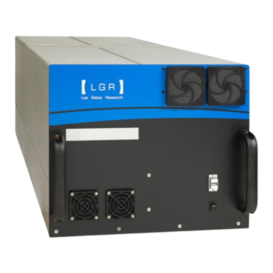
- Page 17 USER MANUAL | ICOS | INSTRUCTIONS | UM/ICOS-EN REV. B.2 Figure 2 shows the front of the analyzer. Figure 2: Front Panel Figure 3 shows the back of the analyzer with connections. Port locations may vary for different analyzer types. Figure 3: Back Panel...
-
Page 18: Power Connections
AC voltage selection on the analyzer matches the AC voltage being supplied from your power supply. EXT. Pump Power Provides power to an external pump when operating the analyzer. If you require a different power source, please contact ABB-LGR. -
Page 19: Data Interface Connection Ports
USER MANUAL | ICOS | INSTRUCTIONS | UM/ICOS-EN REV. B.2 Data Interface Connection Ports This section describes the data interface connections as shown in Figure 5. These connections vary from analyzer to analyzer depending on the ordered configuration. Analog ports– Provides a DC voltage proportional to the measured gas concentration. -
Page 20: Plumbing Diagram
Figure 6 shows an example of the internal flow of gas in standard plumbing analyzers. Configurations will vary depending on the analyzer type and may not include an external pump. For the GLA451-AAQC plumbing diagram, refer to Figure 7. Sample Inlet For standard operation, the pump draws gas through the port on the back panel of the analyzer. -
Page 21: Plumbing Diagram For The Gla431-Aaqc
USER MANUAL | ICOS | INSTRUCTIONS | UM/ICOS-EN REV. B.2 Plumbing Diagram for the GLA431-AAQC For standard operation, the internal pump draws gas through the Sample Inlet port (1/4” Swagelok) on the back panel of the analyzer. The gas travels through a low flow orifice and is filtered through a Teflon Membrane filter. -
Page 22: Fast And Slow Flow Pump Options
USER MANUAL | ICOS | INSTRUCTIONS | UM/ICOS-EN REV. B.2 Fast and Slow Flow Pump Options The analyzer comes equipped with an internal pump. However, the optional external pump provides the ability to achieve up to 10 Hz flow response. In fast-flow mode, you must connect a compatible external pump to the analyzer. -
Page 23: Gas Inlet/Outlet Connections
USER MANUAL | ICOS | INSTRUCTIONS | UM/ICOS-EN REV. B.2 Gas Inlet/Outlet Connections The gas inlet and outlet ports are located on the back panel of the analyzer. (Figure 3) Configurations will vary among analyzer types. These ports are shown in detail in Figure 8. The unit ships with inlets and outlets capped for protection. -
Page 24: Warning Labels And Descriptions
USER MANUAL | ICOS | INSTRUCTIONS | UM/ICOS-EN REV. B.2 Warning Labels and Descriptions This section describes the warning labels shown on the analyzer. Table 6 gives a description of the warning labels. Figure 11 shows the location of the labels on the analyzer. Table 6: Warning Labels and Descriptions Label Description... -
Page 25: Ventilation And Power Requirements
USER MANUAL | ICOS | INSTRUCTIONS | UM/ICOS-EN REV. B.2 Ventilation and Power Requirements TO EXT A continuous flow of air is pumped through the inlet port and out through the PUMP port on the back panel of the analyzer. ... -
Page 26: Analyzer Setup
See Figure 5 for a detailed description of the connections. Connect the Inlet/Outlet Plumbing Connections For the GLA451-N2OI2, GLA451-OCS, GLA451-N2OI3, and GLA451-AAQC, connect the provided exhaust muffler with Swagelok adaptor to the INTERNAL PUMP EXHAUST port to exhaust into the room air, or route to your facility ventilation system, using ¼”... -
Page 27: Attach And Tighten The Swagelok Connectors
USER MANUAL | ICOS | INSTRUCTIONS | UM/ICOS-EN REV. B.2 Attach and Tighten the Swagelok Connectors Tighten the Swagelok connections to between 1/4 and 1/2 turn past finger tight. Leave a gap of at least 3.5 mm as shown in Figure 13. 2. -
Page 28: Initialize And Run The Analyzer
2. Click on the launch button button to manually launch the analyzer. a. The launch button is the abbreviated name of the gas analyzer. For example, the GLA451-OCS button displays OCS. (Figure 16) b. If you don’t make a selection within 120-seconds, the analyzer automatically... -
Page 29: File System Integrity Check
USER MANUAL | ICOS | INSTRUCTIONS | UM/ICOS-EN REV. B.2 File System Integrity Check Once a month, the analyzer automatically performs a file system integrity check following initialization. Figure 15 shows the screen you see while the integrity check runs. The integrity check runs for one to two minutes before launching the analyzer’s control software. -
Page 30: The Launch Service Screen
Bypass the auto launch countdown to manually start recording measurements by clicking the launch button. The launch button is the abbreviated name of the gas analyzer. For example, the GLA451-OCS launch button displays OCS as shown in Figure Open the auto launch window by clicking Service. -
Page 31: The Auto Launch Screen
USER MANUAL | ICOS | INSTRUCTIONS | UM/ICOS-EN REV. B.2 The Auto Launch Screen The Auto Launch and Maintenance settings are available when you click the Service button Launch Service on the screen. From this interface, you can: Change the auto launch delay timing. ... -
Page 32: Login To Access Menu Options
USER MANUAL | ICOS | INSTRUCTIONS | UM/ICOS-EN REV. B.2 Login to Access Menu Options To access the analyzer user interface features, log into the system as follows: User Interface Control Bar 1. Click the Security button on the . (Figure 18) Figure 18: Control Bar Security Button 2. -
Page 33: Main Panel
USER MANUAL | ICOS | INSTRUCTIONS | UM/ICOS-EN REV. B.2 Main Panel Main Panel After the software launches, the is displayed. Figure 20 shows an example of a Main Panel . The gases displayed are dependent on the type of analyzer. The operational status of the analyzer is displayed at the bottom of the main panel: ... -
Page 34: User Interface Control Bar
USER MANUAL | ICOS | INSTRUCTIONS | UM/ICOS-EN REV. B.2 User Interface Control Bar Use the control bar to operate the analyzer. Figure 21: User Interface Control Bar... - Page 35 USER MANUAL | ICOS | INSTRUCTIONS | UM/ICOS-EN REV. B.2 Main Panel Display – Toggles through the four display formats: Numeric Display – Default display. Displays the numeric readout of the last measurement. (Figure 22) Alarm Status Display –...
-
Page 36: Main Panel Displays
USER MANUAL | ICOS | INSTRUCTIONS | UM/ICOS-EN REV. B.2 Main Panel Displays Main Panel Click the Display button to change the display in the . Clicking the Display button multiple times lets you cycle through the four main panel displays. When the Numeric Display analyzer is launched, it defaults to the . -
Page 37: Alarm Status Display
USER MANUAL | ICOS | INSTRUCTIONS | UM/ICOS-EN REV. B.2 Alarm Status Display Alarm Status display (Figure 23) shows the detailed operational status of the analyzer. Alarm Status is color-coded: Green : The analyzer is functioning properly Yellow: The data may not reliable, or maintenance is required soon. ... - Page 38 USER MANUAL | ICOS | INSTRUCTIONS | UM/ICOS-EN REV. B.2 Table 8 describes fault criteria for the Temperature Alarms. Table 8: Fault Criteria for Temperature Alarms Status Sensor Read Fault Condition Description Temperature High/Low The temperature exceeds the operating Analyzer Temp Alarm temperature range.
- Page 39 Analyzer maintenance will be needed soon (every Maintenance needed soon 360 days). Dead Band Performance No warning/alarm No warning/alarm Alarm Status Maintenance If the is Yellow or Red, please refer to the section on page 65. If issue continues, please contact icos.support@ca.abb.com...
-
Page 40: Spectrum Display
USER MANUAL | ICOS | INSTRUCTIONS | UM/ICOS-EN REV. B.2 Spectrum Display User Interface Control Bar Spectrum Display Click the Display button on the to switch to The top plot shows the voltage from the photo-detector as the laser scans across the absorption features. - Page 41 Spectrum Displays Figure 25 shows a in dry air. Figure 25: Spectrum Display (Dry Air) Table 10: Spectrum Displays for different analyzer types Analyzer Type Figure for Reference GLA451-AAQC Figure 115 GLA451-N2OI2 Figure 116 GLA451-N2OI3 Figure 117 GLA451-OCS Figure 118...
-
Page 42: Time Chart Display
USER MANUAL | ICOS | INSTRUCTIONS | UM/ICOS-EN REV. B.2 Time Chart Display Click the Display button on the User Interface Control Bar to switch to the TimeChart Display. TimeChart Display is a real-time measurement of concentration vs. time. Time Chart Figure 26 shows the with a continuous flow of gas. -
Page 43: Rate Control
Selections in this window will vary, depending on analyzer type. Figure 27: Rate Control Screen (GLA451-N2OI3) Operating Mode radio buttons allow you to change the rate at which data is written to the log file. - Page 44 USER MANUAL | ICOS | INSTRUCTIONS | UM/ICOS-EN REV. B.2 Batch Injection System For select analyzers, the allows you to manually introduce individual Batch Mode Operation samples to the analyzer, using syringe injection. (Figure 27) See page 100 for more information. for Batch Mode Operation Click the Syringe Injection radio button Plot Frequency...
-
Page 45: File Transfer Menu
USER MANUAL | ICOS | INSTRUCTIONS | UM/ICOS-EN REV. B.2 File Transfer Menu File Transfer Use the menu to access data collected by the analyzer. Each time the analyzer is re-started, the most recent file name is displayed in the form: xxx_2020-12-29_f0001.txt, where the: First characters represent the analyzer model Next 10 characters represent the date (yyyy-mm-dd) -
Page 46: Transfer Data Files
USER MANUAL | ICOS | INSTRUCTIONS | UM/ICOS-EN REV. B.2 Transfer Data Files To transfer data files from the analyzer hard drive to a USB storage device: User Interface Control Bar Click the Files button on the (Figure 21) to access the File Transfer Menu . - Page 47 USER MANUAL | ICOS | INSTRUCTIONS | UM/ICOS-EN REV. B.2 When you have finished transferring files: 5. Click the Unmount USB button. Safe to Remove USB Memory Device Wait for the message before removing the USB memory device. File Transfer Menu 6.
-
Page 48: Types Of Directories In The Local Hard Drive
USER MANUAL | ICOS | INSTRUCTIONS | UM/ICOS-EN REV. B.2 Types of directories in the local hard drive The analyzer hard drive contains two types of directories: Daily Directory Archive Directory Daily Directory The local hard drive (Figure 29) creates a daily folder containing new data files for each day that the analyzer operates. -
Page 49: Archive Directory
USER MANUAL | ICOS | INSTRUCTIONS | UM/ICOS-EN REV. B.2 Archive Directory The local hard drive (Figure 29) creates an archived folder containing zipped files organized by date. (Figure 31) To access the archived files, double-click the Archive folder. (Figure 29) Each file is a single zipped .txt file, using the following convention: YYYY-MM-DD.zip. -
Page 50: File Transfer Error Screen
USER MANUAL | ICOS | INSTRUCTIONS | UM/ICOS-EN REV. B.2 File Transfer Error Screen File Transfer Error screen (Figure 32) displays when: The USB Key does not have enough storage space. The device is not recognized. Try again with a correctly inserted USB device. Figure 32: File Transfer Error... -
Page 51: Setup Menu
USER MANUAL | ICOS | INSTRUCTIONS | UM/ICOS-EN REV. B.2 Setup Menu Setup menu allows access to additional configurations and services. Selections in this menu will vary, depending on analyzer type. Setup To enter mode: Click the Setup button on the User Interface Control Bar . -
Page 52: Time/Files Tab
USER MANUAL | ICOS | INSTRUCTIONS | UM/ICOS-EN REV. B.2 Setup menu has function tabs at the top of the screen that allows you to configure the analyzer mode and settings. (Figure 34) These tabs will vary among analyzer types. These tabs let you: ... - Page 53 USER MANUAL | ICOS | INSTRUCTIONS | UM/ICOS-EN REV. B.2 Local Time Zone Local Time Zone menu lets you adjust the current local time zone by selecting an option from the drop-down selection box. Clock Clock menu lets you manually adjust the current time and date settings. File Output File Output menu lets you adjust the timestamp format of the data files.
- Page 54 USER MANUAL | ICOS | INSTRUCTIONS | UM/ICOS-EN REV. B.2 Serial Output Serial Output menu lets you change how the data reported at the RS-232 port is configured. Standard settings are provided for: Baud Rate Parity Stop Bits The actual rate of the serial output is equal to the Logged File Rate (i.e.
-
Page 55: Calibration Tab
USER MANUAL | ICOS | INSTRUCTIONS | UM/ICOS-EN REV. B.2 Calibration Tab ABB-LGR recommends periodic referencing rather than calibration to ensure measurement accuracy and consistency. When calibration is necessary, follow the procedure detailed below. Calibration Procedure: Click the Setup button on the User Interface Control Bar . - Page 56 USER MANUAL | ICOS | INSTRUCTIONS | UM/ICOS-EN REV. B.2 4. Enter the known concentration for your local gas standard. 5. Connect your reference gas supply to the ¼” Swagelok inlet port on the back panel of the analyzer. (Figure 3) 6.
-
Page 57: Laser Adjust Tab
USER MANUAL | ICOS | INSTRUCTIONS | UM/ICOS-EN REV. B.2 Laser Adjust Tab Laser Adjust Use the tab to manually adjust the laser’s wavelength to compensate for any cumulative drift. (Figure 38) Laser adjustment may be needed for the following reasons: ... - Page 58 USER MANUAL | ICOS | INSTRUCTIONS | UM/ICOS-EN REV. B.2 Manually Adjust the Laser Offset User Interface Control Bar Click the Setup button on the . (Figure 33) 2. Select the Laser Adjust tab at the top of the screen. (Figure 38) 3.
- Page 59 USER MANUAL | ICOS | INSTRUCTIONS | UM/ICOS-EN REV. B.2 Figure 40: Absorption Peaks Centered Correctly on Target Lines (Ambient Air)
-
Page 60: Miu Tab
USER MANUAL | ICOS | INSTRUCTIONS | UM/ICOS-EN REV. B.2 MIU tab The optional Multi-Port Inlet Unit (MIU-8 or MIU-16) is an ABB-LGR accessory that allows automated control of 8 or 16 inlet ports (depending on the ordered configuration). These ports are directed to the inlet port of the analyzer for sampling unknown gases and reference gases. -
Page 61: Analog Output Tab
USER MANUAL | ICOS | INSTRUCTIONS | UM/ICOS-EN REV. B.2 Analog Output Tab Analog Output port has a 16-bit voltage range from 0 to 5 volts. The user can specify a conversion between gas concentrations and the analog output voltage, using the spinner controls, or by manually typing a number into the field. The dropdown spinner controls let you select the concentration value that will correspond to the maximum 5 VDC analog output. -
Page 62: Dcs Tab
DCS Tab The External Dynamic Dilution System (EDDS) is an optional accessory. The EDDS is an ABB accessory that dilutes sample gas with zero-air whenever the concentration rises above the target. It extends the upper range up to 100x through automated dilution and maintains the target concentration at that level. -
Page 63: Service Tab
USER MANUAL | ICOS | INSTRUCTIONS | UM/ICOS-EN REV. B.2 Service Tab Service ABB-trained field service engineers monitor the performance of the analyzer via the screen. (Figure 44) These settings determine the level of change that could affect measurement performance. -
Page 64: Shutting Down The Analyzer
USER MANUAL | ICOS | INSTRUCTIONS | UM/ICOS-EN REV. B.2 Shutting Down the Analyzer To shut down the analyzer: User Interface Control Bar Click the Exit button on the . (Figure 45) Main Panel 2. A pop-up box appears on the and prompts you to verify that you want to shut down the analyzer to prevent accidental button presses from causing interruption in data acquisition. -
Page 65: Maintenance
Measurement cell mirrors are protected from contamination by an internal inlet filter. With continued use the mirrors may gradually decline in reflectivity. For the GLA451-OCS, if a significant change occurs in the mirror ring-down time (for example, greater than 20% reduction), the precision of the measurements may be reduced. -
Page 66: Replace The Power Inlet Fuse
USER MANUAL | ICOS | INSTRUCTIONS | UM/ICOS-EN REV. B.2 Replace the Power Inlet Fuse If the fuse on the power inlet blows or is otherwise damaged, the analyzer shuts down. To replace the fuse: Unplug the analyzer. 2. On the back panel of the analyzer, locate the fuse above the power inlet. (Figure 48) Figure 48: Analyzer Fused Inlet 3. -
Page 67: Appendix A: About Gas Analyzers And Laser Absorption Spectroscopy
USER MANUAL | ICOS | INSTRUCTIONS | UM/ICOS-EN REV. B.2 Appendix A: About Gas Analyzers and Laser Absorption Spectroscopy Conventional Laser Absorption Spectroscopy For gas measurements based on conventional laser-absorption spectroscopy (Figure 51), a laser beam is directed through a sample, and the mixing ratio (or mole fraction) of a gas is determined from the measured absorption using Beer’s Law, which may be expressed: Where: ... - Page 68 USER MANUAL | ICOS | INSTRUCTIONS | UM/ICOS-EN REV. B.2 Integration of the measured spectra with the measured values of: Gas temperature Gas pressure Path length Line strength of the probed transition Enables you to determine the mole fraction directly from the relation: Use this equation to determine gas concentrations, even in hostile environments without using calibration gases or reference standards.
-
Page 69: Abb-Lgr's Off-Axis Integrated-Cavity Output Spectroscopy (Off-Axis Icos)
USER MANUAL | ICOS | INSTRUCTIONS | UM/ICOS-EN REV. B.2 ABB-LGR’s Off-Axis Integrated-Cavity Output Spectroscopy (Off-Axis ICOS) Off-Axis ICOS uses a high-finesse optical cavity as an absorption cell as shown in Figure 52. Unlike multi-pass detectors, which are typically limited to path lengths of less than two hundred meters, an Off-Axis ICOS absorption cell effectively traps the laser photon so that, on average, they make thousands of passes before leaving the cell. -
Page 70: Appendix B: Accessing Data Using The Ethernet
USER MANUAL | ICOS | INSTRUCTIONS | UM/ICOS-EN REV. B.2 Appendix B: Accessing Data Using the Ethernet Appendix B explains how to access the analyzer data directory as a Windows Share using an Ethernet connection on a local area network (LAN). The data files stored on the internal hard disk drive of the analyzer can be accessed as a Windows Share over a Local Area Network (LAN) Ethernet connection. - Page 71 USER MANUAL | ICOS | INSTRUCTIONS | UM/ICOS-EN REV. B.2 Additional Notes The analyzer shared data directory is in the LGR workgroup. If it is not visible, browse for it in the Windows Network Neighborhood by entering the IP address of the analyzer. Figure 35 shows the location of the IP address.
-
Page 72: Appendix C: Wireless Router Setup (Optional)
USER MANUAL | ICOS | INSTRUCTIONS | UM/ICOS-EN REV. B.2 Appendix C: Wireless Router Setup (Optional) The analyzer can be ordered with an optional TP-Link wireless router. If you ordered the wireless router option, it will be factory installed inside, or on the side of, the analyzer. Configuration Options Access-Point Mode The router is shipped in Access-Point mode, by default. - Page 73 USER MANUAL | ICOS | INSTRUCTIONS | UM/ICOS-EN REV. B.2 Configure Router for Access-Point Mode Using a phone, tablet, or laptop, connect to the router using the SSID and password on the router. (Figure 53) Figure 53: Router SSID and Password Location 2.
- Page 74 USER MANUAL | ICOS | INSTRUCTIONS | UM/ICOS-EN REV. B.2 5. On the left panel, click Quick Setup. (Figure 55) Figure 55: Start Router Configuration 6. Click Next. 7. In the Main Panel , select the Access Point button. (Figure 55) 8.
- Page 75 USER MANUAL | ICOS | INSTRUCTIONS | UM/ICOS-EN REV. B.2 Network Setting 10. In the screen, click Next. (Figure 57) Figure 57: Network Setting Screen 11. Click Finish. 12. Restart the analyzer.
- Page 76 USER MANUAL | ICOS | INSTRUCTIONS | UM/ICOS-EN REV. B.2 Connect Analyzer to Local Network LAN/WAN Unplug the black cable from the router port. (Figure 58) Figure 58: Unplug Cable and Remove Ethernet Union 2. Remove the Ethernet union (next to the router). (Figure 58) 3.
-
Page 77: Appendix D: Set Up Devices For Remote Access Using Vnc Software
USER MANUAL | ICOS | INSTRUCTIONS | UM/ICOS-EN REV. B.2 Appendix D: Set Up Devices for Remote Access Using VNC Software Listed below are three types of devices that can be connected to the analyzer through the wireless router to access information: ... - Page 78 USER MANUAL | ICOS | INSTRUCTIONS | UM/ICOS-EN REV. B.2 6. A verification message appears, showing that the Android device is connected to the router. (Figure 61) Figure 61: Connectivity Confirmation Screen 7. Ensure that the IP address of the Android device is correct by holding your finger down on the network connection icon.
- Page 79 USER MANUAL | ICOS | INSTRUCTIONS | UM/ICOS-EN REV. B.2 10. Open the VNC application on the Android device by selecting the VNC application icon. (Figure 63) Figure 63: VNC Application Icon 11. The Android VNC screen appears. (Figure 64) Figure 64: VNC Application Installation Setup Screen Address 12.
- Page 80 USER MANUAL | ICOS | INSTRUCTIONS | UM/ICOS-EN REV. B.2 14. Tap the Connect button to connect the Android device to the analyzer. The analyzer software interface screen displays on the device. The screen size is adjustable to fit the screen of the device. (Figure 65) Figure 65: Analyzer Software Interface Display with Size Adjustment for Android Devices...
- Page 81 USER MANUAL | ICOS | INSTRUCTIONS | UM/ICOS-EN REV. B.2 Set up VNC Software on iOS Devices On the iOS device, go to Settings > WiFi, then select the network from the list. 2. Connect to the wireless SSID network listed on the router sticker. (Figure 53) Enter the TP-Link wireless router.
- Page 82 USER MANUAL | ICOS | INSTRUCTIONS | UM/ICOS-EN REV. B.2 Network Connections 6. The screen confirms that the iOS device is connected to the router. (Figure 68) Figure 68: Router Connection Confirmation Screen 7. Select the network to check the IP address (192.168.100.100 or 192.168.100.101) of the device as shown in Figure 69.
- Page 83 USER MANUAL | ICOS | INSTRUCTIONS | UM/ICOS-EN REV. B.2 Figure 70: VNC Selection Screen 10. Open the application and select Configure. (Figure 71) Figure 71: Mocha VNC Lite Configure (New) Screen Configure Screen 11. The prompts you for the server IP address and password. (Figure Figure 72: Mocha VNC Lite Configure Screen 12.
- Page 84 USER MANUAL | ICOS | INSTRUCTIONS | UM/ICOS-EN REV. B.2 14. Select Connect. Setup Configuration screen displays the IP address. (Figure 73) Figure 73: Setup Configurations Screen 15. To connect the iOS device to the analyzer, tap the IP Config you set up. The analyzer software will display on the device.
- Page 85 USER MANUAL | ICOS | INSTRUCTIONS | UM/ICOS-EN REV. B.2 Set up VNC Software on Windows Devices On the Windows device, open Wireless Router options. 2. Locate the sticker on the router. (Figure 53) 3. Click on the Wireless Network Connections icon in the bottom left of the screen Windows Wireless Networks (Figure 75) to open the dialog-box.
- Page 86 USER MANUAL | ICOS | INSTRUCTIONS | UM/ICOS-EN REV. B.2 6. Click OK. Figure 77: Network Connections Security Screen 7. The Connection Status dialog-box displays. (Figure 78) Figure 78: Current Connectivity Screen...
- Page 87 USER MANUAL | ICOS | INSTRUCTIONS | UM/ICOS-EN REV. B.2 8. Check the connection to make sure the device is connected through the wireless router by selecting the router. (Figure 79) Figure 79: Wireless Network Connection Screen 9. Verify the IP address of the Windows device: a.
- Page 88 USER MANUAL | ICOS | INSTRUCTIONS | UM/ICOS-EN REV. B.2 Wireless Network Connection Status 10. The dialog-box displays. (Figure 81) Figure 81: Wireless Network Connection Status Window Network Connection Details 11. Click the Details button to display the window. (Figure Figure 82: Network Connection Details Window...
- Page 89 USER MANUAL | ICOS | INSTRUCTIONS | UM/ICOS-EN REV. B.2 Ipv4 Address 12. Verify the of the Windows device, which should be either 192.168.100.100 or 192.168.100.101. For example, the Windows device IP address is 192.168.100.101. (Figure 82) RealVNC 13. Install the VNC software by going to the website and downloading the RealVNC Viewer “EXE”...
-
Page 90: Appendix E: Multi-Port Inlet Unit (Optional)
By sampling references periodically during an ongoing data run, you can post-correct the data for long-term drift when active calibration cannot be done. ABB-LGR offers two versions of the MIU: 8 port ... - Page 91 USER MANUAL | ICOS | INSTRUCTIONS | UM/ICOS-EN REV. B.2 Figure 85 shows the back panel of a 16 port MIU. The MIU inlet ports are labeled numerically on the back panel of the MIU. The outlet port connects to the gas inlet on the analyzer.
- Page 92 USER MANUAL | ICOS | INSTRUCTIONS | UM/ICOS-EN REV. B.2 Control the MIU Using the Analyzer Setup Panel User Interface Control Bar. Click Setup on the (Figure 88) Setup 2. Click on the MIU tab at the top of the menu selection bar.
- Page 93 USER MANUAL | ICOS | INSTRUCTIONS | UM/ICOS-EN REV. B.2 3. Populate the unknown gas valve sequence: a. Valve - The current valve being sampled (corresponds to the port number on the MIU). b. Seconds - How long the analyzer should sample the gas (in seconds). c.
- Page 94 USER MANUAL | ICOS | INSTRUCTIONS | UM/ICOS-EN REV. B.2 6. Use the arrow scroll bar to select the number of times to run the unknown gas sequence for each reference gas sequence. (Figure 87) 7. Select Save Changes to save your current configuration. 8.
-
Page 95: Appendix F: External Dynamic Dilution System (Optional)
USER MANUAL | ICOS | INSTRUCTIONS | UM/ICOS-EN REV. B.2 Appendix F: External Dynamic Dilution System (Optional) The External Dynamic Dilution System (EDDS) is an optional accessory. This section describes the EDDS and explains setup and operation. Figure 89: EDDS Front & Back Panel The EDDS: ... - Page 96 USER MANUAL | ICOS | INSTRUCTIONS | UM/ICOS-EN REV. B.2 Connect the EDDS This section describes the EDDS hardware and how to connect it. (Figure 90) Control cable – Connect the BNC cable between: a. The CONTROL IN port on the EDDS b.
- Page 97 Sample Inlet Tee Connector The diluted gas flows into analyzer through a T-connector that allows for steady flow past the inlet to the analyzer. (Figure 91) ABB-LGR recommends these T-connectors: 1/4” inlet: Swagelok SS-400-3 3/8” inlet: Swagelok SS-600-3 Figure 91: Inlet T-Configuration for the EDDS If you do not use the inlet tee, and connect the gases directly to the analyzer, the mass flow controllers will not maintain proper dilution.
- Page 98 USER MANUAL | ICOS | INSTRUCTIONS | UM/ICOS-EN REV. B.2 Optional External Throttle Valve An optional external throttle valve (Figure 92) lets you adjust the gas flow to the analyzer. Use the throttle valve to restrict the: Total flow into the analyzer to less than 200 SCCM ...
- Page 99 USER MANUAL | ICOS | INSTRUCTIONS | UM/ICOS-EN REV. B.2 Enable the EDDS User Interface Control Bar Click Setup on the . (Figure 93) Figure 93: Setup button on the User Interface Control Bar Setup 2. Click on the DCS tab at the top of the menu selection bar.
-
Page 100: Appendix G: Fast-Flow Operation
USER MANUAL | ICOS | INSTRUCTIONS | UM/ICOS-EN REV. B.2 Appendix G: Fast-Flow Operation Analyzers with the Fast-flow feature: Measure data at a higher flow rate than a standard analyzer. Use an external pump to increase the flow rate of gas during measurement. ... - Page 101 USER MANUAL | ICOS | INSTRUCTIONS | UM/ICOS-EN REV. B.2 Figure 96 shows the plumbing diagram of a GLA451-AAQC. Figure 96: Plumbing diagram for Fast -Flow Mode (AAQC) During high-flow mode, the External pump is on and then Internal pump is off. The external throttle valve (Figure 97) is used in conjunction with the electronic pressure controller to adjust the flow through the analyzer.
- Page 102 USER MANUAL | ICOS | INSTRUCTIONS | UM/ICOS-EN REV. B.2 Figure 97 shows the external throttle valve assembly. Figure 97: High Flow Throttle Valve Fast-Flow Setup and Operation Connect the optional External Pump. a. Connect the external pump’s power cord from the pump to the EXT. PUMP POWER port on the back panel of the analyzer.
- Page 103 USER MANUAL | ICOS | INSTRUCTIONS | UM/ICOS-EN REV. B.2 Internal Pump Exhaust 3. Cap the port with the provided ¼” Swagelok cap. User Interface Control Bar 4. Click the Rate button (clock icon) on the (Figure 98) to access the Data Rate Control Adjustment Panel. (Figure 99) Operating Mode FAST 5.
- Page 104 The maximum range and reading display of the pressure transducer is approximately 155 Torr—any time the cell pressure is above 155 Torr the display will remain locked at 155 Torr. To determine if your analyzer is capable of fast-flow mode, contact ABB-LGR at icos.support@ca.abb.com .
-
Page 105: Appendix H: Batch Mode Operation
USER MANUAL | ICOS | INSTRUCTIONS | UM/ICOS-EN REV. B.2 Appendix H: Batch Mode Operation The analyzer can be factory equipped to include a batch injection system. The batch system allows the user to manually introduce individual samples to the analyzer, using syringe injection. - Page 106 USER MANUAL | ICOS | INSTRUCTIONS | UM/ICOS-EN REV. B.2 Hardware Setup Setup the External Connections: Connect the External Pump: EXT. PUMP POWER a. Connect the pump’s power cord from the pump to the port on the back panel of the analyzer. b.
- Page 107 USER MANUAL | ICOS | INSTRUCTIONS | UM/ICOS-EN REV. B.2 Software Setup User Interface Control Bar If applicable, in the parameter window of the , verify that the optional MIU and WVISS accessories are not enabled. (Figure 103) Multi-Port Inlet Unit (MIU) a.
- Page 108 USER MANUAL | ICOS | INSTRUCTIONS | UM/ICOS-EN REV. B.2 b. Disable the Water Vapor Isotope Standard Source (WVISS) if your analyzer is configured with this optional accessory. To disable the WVISS: User Interface Control Bar Click Setup on the .
- Page 109 USER MANUAL | ICOS | INSTRUCTIONS | UM/ICOS-EN REV. B.2 2. Select Batch Injection mode in the analyzer software: User Interface Control Bar a. Click the RATE button (clock icon) in the . (Figure 107) Figure 107: Click the Rate Button 3.
- Page 110 USER MANUAL | ICOS | INSTRUCTIONS | UM/ICOS-EN REV. B.2 Batch Injection Measurement 5. The screen displays. (Figure 109) Main Panel a. This screen combines the three display modes on one screen: Numeric Display Spectrum Display TimeChart Display Batch Mode Status b.
- Page 111 USER MANUAL | ICOS | INSTRUCTIONS | UM/ICOS-EN REV. B.2 Batch Mode Processing batch processing mode, the analyzer: Initiates the batch injection procedure. 2. Evacuates the cavity. 3. Flushes the cavity with zero air twice before requesting the sample. 4. Prompts you to inject sample (of >60 ml) gas into the syringe port. a.
- Page 112 USER MANUAL | ICOS | INSTRUCTIONS | UM/ICOS-EN REV. B.2 To begin batch mode processing: Batch Mode Status a. Click NEXT in the display box. (Figure 109) Each step is displayed in the lower-right panel of the screen as the analyzer prepares for the injection.
- Page 113 USER MANUAL | ICOS | INSTRUCTIONS | UM/ICOS-EN REV. B.2 Changing the Septa on the Syringe Injection Port The septum on the syringe injection port requires periodic replacement. Depending on use, a septum should last a minimum of 100 injections. To replace the septum: Click the Rate button on the User Interface Control Bar...
- Page 114 USER MANUAL | ICOS | INSTRUCTIONS | UM/ICOS-EN REV. B.2 7. Slide the septum nut and new septum onto the provided blunt 22-gauge needle. The Teflon-coated side of the septum must face away from the septum nut. (Figure 113) Figure 113: Septum inserted on needle with Teflon coating facing away from the septum 8.
-
Page 115: Appendix I:spectrum Displays
Appendix I:Spectrum Displays Analyzer Type Figure for Reference GLA451-AAQC Figure 115 GLA451-N2OI2 Figure 116 GLA451-N2OI3 Figure 117 GLA451-OCS Figure 118 GLA451-AAQC Enhanced Performance QC Benchtop Trace Ammonia Analyzer Spectrum Display Figure 115 shows the for the GLA451-AAQC. Figure 115: Spectrum Display (GLA451-AAQC) -
Page 116: Gla451-N2Oi2 Enhanced Performance Qc Benchtop Isotopic Nitrous Oxide Analyzer
USER MANUAL | ICOS | INSTRUCTIONS | UM/ICOS-EN REV. B.2 GLA451-N2OI2 Enhanced Performance QC Benchtop Isotopic Nitrous Oxide Analyzer Spectrum Display Figure 116 shows the for the GLA451-N2OI2. Figure 116: Spectrum Display (GLA451-N2OI2) -
Page 117: Gla451-N2Oi3 Enhanced Performance Qc Benchtop Isotopic Nitrous Oxide Analyzer
USER MANUAL | ICOS | INSTRUCTIONS | UM/ICOS-EN REV. B.2 GLA451-N2OI3 Enhanced Performance QC Benchtop Isotopic Nitrous Oxide Analyzer Spectrum Display Figure 117 shows the for the GLA451-N2OI3. Figure 117: Spectrum Display (GLA451-N2OI3) -
Page 118: Gla451-Ocs Enhanced Performance Qc Benchtop Carbonyl Sulfide Analyzer
USER MANUAL | ICOS | INSTRUCTIONS | UM/ICOS-EN REV. B.2 GLA451-OCS Enhanced Performance QC Benchtop Carbonyl Sulfide Analyzer Spectrum Display Figure 118 shows the for the GLA451-OCS. Figure 118: Spectrum Display (GLA451-OCS) -
Page 119: Appendix J: Cables
USER MANUAL | ICOS | INSTRUCTIONS | UM/ICOS-EN REV. B.2 Appendix J: Cables Table 13 describes the power cables shipped with your analyzer. Table 13: Power Cables Region Cable Specifications Australia and New Zealand United Kingdom... - Page 120 USER MANUAL | ICOS | INSTRUCTIONS | UM/ICOS-EN REV. B.2 Europe United States...
- Page 121 We reserve the right to make technical changes or modify the contents of this document without prior notice. With regard to purchase orders, the agreed particulars shall prevail. ABB does not accept any responsibility whatsoever for potential errors or possible lack of information in this document.