
Related Manuals for ABB ICOS GLA431-MCIA


Summary of Contents for ABB ICOS GLA431-MCIA
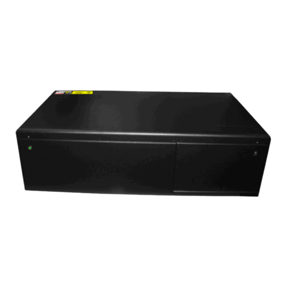
- Page 1 — ABB MEASUREMENT & ANALYTICS | USER MANUAL User Manual | ICOS GLA431-MCIA Enhanced Performance Benchtop Continuous Flow Analyzer...
-
Page 2: Table Of Contents
USER MANUAL | ICOS | INSTRUCTIONS | UM/ICOS-EN REV. B.2 Table of Contents Disclaimer ............................5 Cyber Security ..........................5 Patent .............................. 5 Copyright ............................5 Safety .............................. 6 Class of Laser Equipment ......................6 Certification ..........................6 WEEE Directive ........................... 6 Labels ............................ - Page 3 USER MANUAL | ICOS | INSTRUCTIONS | UM/ICOS-EN REV. B.2 Initialize and Run the Analyzer ..................... 25 File System Integrity Check ...................... 26 Thermal Stabilization ......................... 26 The Launch Service Screen ......................27 The Auto Launch Screen ......................28 Login to Access Menu Options ....................29 Main Panel ............................
- Page 4 USER MANUAL | ICOS | INSTRUCTIONS | UM/ICOS-EN REV. B.2 Appendix H: Cables ......................... 109...
-
Page 5: Disclaimer
ABB and its affiliates are not liable for damages and/or losses related to such security breaches, any unauthorized access, interference, intrusion, leakage and/or theft of data or information. -
Page 6: Safety
USER MANUAL | ICOS | INSTRUCTIONS | UM/ICOS-EN REV. B.2 Safety The following pages provide important safety precautions. Class of Laser Equipment The analyzer is a Class 1 laser instrument when the case cover is closed for normal operation, and the lock is installed. Certification The analyzer certifications are listed in Table 1. -
Page 7: Labels
USER MANUAL | ICOS | INSTRUCTIONS | UM/ICOS-EN REV. B.2 Labels The following labels are at specific locations on or in the analyzer to identify hazardous areas. (Figure 1) Figure 1: Radiation Labels These labels are located on the enclosure covering the ICOS cell. The fiber laser is visible only when the insulated enclosure is removed from the ICOS cell. -
Page 8: Laser Hazards
Only trained service personnel are authorized to open the housing or service the laser. Using this analyzer in a manner not specified by ABB-LGR may result in damage to the analyzer and render it unsafe to operate. Only authorized persons may open the analyzer cover or perform internal maintenance. -
Page 9: Text Formats And Warning Icons
USER MANUAL | ICOS | INSTRUCTIONS | UM/ICOS-EN REV. B.2 Text Formats and Warning Icons Text Formats This section describes text formats and warning icons used in this manual. Italicized text is used for emphasis in text and also to emphasize the names •... -
Page 10: Transportation And Storage Of Boxed Analyzers
Save the original shipping materials to use when returning the analyzer to ABB-LGR if factory service or repair is needed. Table 3 lists and describes the safety icons on ABB-LGR shipping boxes. Follow these instructions when transporting and storing boxed analyzers. -
Page 11: Warranty
Customer Support ABB provides product support services worldwide. To receive product support, either in or out of warranty, contact the ABB office that serves your geographical area, or the office indicated below: ABB Inc. Measurement & Analytics 3400, rue Pierre-Ardouin... -
Page 12: Analyzer Overview
Fuse Ratings 250 VAC • 10 Amps • Cable Plugs and Voltage for EC Countries See page 109 • Always use the power supply cord provided by ABB-LGR. See page 109 for a description of power cords for a specific country. -
Page 13: Standard Components
Tee connector for the analyzer inlet port • This analyzer has been CE certified using data cables three meters long or less. Connecting the analyzer using longer data-cables is not recommended. If you have not received all of these components, contact ABB-LGR at icos.support@ca.abb.com. - Page 14 USER MANUAL | ICOS | INSTRUCTIONS | UM/ICOS-EN REV. B.2 Figure 2 shows the front of the analyzer. Figure 2: Front Panel Figure 3 shows the back of the analyzer with connections. Figure 3: Back Panel...
-
Page 15: Power Connections
AC Power In Connects the analyzer to the power supply EXT. Pump Power Provides power to an external pump when operating the analyzer. If you require a different power source, please contact ABB-LGR. -
Page 16: Data Interface Connection Ports
USER MANUAL | ICOS | INSTRUCTIONS | UM/ICOS-EN REV. B.2 Data Interface Connection Ports This section describes the data interface connections as shown in Figure 5. These connections may vary depending on analyzer types. Ethernet port – Connects the analyzer to a local area network (LAN) and allows •... -
Page 17: Plumbing Diagram
USER MANUAL | ICOS | INSTRUCTIONS | UM/ICOS-EN REV. B.2 Plumbing Diagram The plumbing diagram measures the internal flow of gas through the analyzers. The external pump draws gas through the Sample Inlet port ( ” Swagelok) on the back panel of the analyzer, and the waste is exhausted through the To External Pump port (3/8” Swagelok). -
Page 18: Inlet/Outlet Connections
USER MANUAL | ICOS | INSTRUCTIONS | UM/ICOS-EN REV. B.2 Inlet/Outlet Connections The inlet and outlet ports are located on the back panel of the analyzer. (Figure 3) These ports are shown in detail in Figure 8. The unit ships with inlets and outlets capped for protection. The connections use Swagelok fittings ISO thread size 1/4”... -
Page 19: Warning Labels And Descriptions
USER MANUAL | ICOS | INSTRUCTIONS | UM/ICOS-EN REV. B.2 Warning Labels and Descriptions This section describes the warning labels shown on the analyzer. Table 5 gives a description of the warning labels. • Figure 9 shows the location of the labels on the analyzer. •... -
Page 20: Specifications
USER MANUAL | ICOS | INSTRUCTIONS | UM/ICOS-EN REV. B.2 Specifications This section provides the weight and dimensions of the analyzer. (Figure 10) External Dimensions 11” H x 38” W x 22” D Weight 40 kg Figure 10: Front Panel Dimensions... -
Page 21: Analyzer Setup
USER MANUAL | ICOS | INSTRUCTIONS | UM/ICOS-EN REV. B.2 Analyzer Setup Connect the Power Cords Connect the analyzer power cord from the AC power port on the back panel to a grounded outlet of your power supply. (Figure 3) 2. Connect the External pump’s power cord from the pump to the EXT. PUMP POWER port on the back panel of the analyzer. -
Page 22: The Pretreatment Box
USER MANUAL | ICOS | INSTRUCTIONS | UM/ICOS-EN REV. B.2 The Pretreatment Box The pretreatment box dries the sample, so the water concentration is maintained below 500 ppm. The pretreatment box removes ambient CO and dries the sample, so the water concentration is maintained below 500 ppm. Replace the soda lime filter as needed (normally at six week intervals). -
Page 23: Connect The Pretreatment Box, Pump, And Analyzer
USER MANUAL | ICOS | INSTRUCTIONS | UM/ICOS-EN REV. B.2 Connect the Pretreatment Box, Pump, and Analyzer Connect the external pump to the pretreatment box TO EXT. PUMP port using the 6’ x 3/8” Swagelok connector and tubing (provided). 2. Connect the external pump’s power cord from the pump to the EXT. PUMP POWER outlet on the analyzer. -
Page 24: Attach And Tighten The Swagelok Connectors
USER MANUAL | ICOS | INSTRUCTIONS | UM/ICOS-EN REV. B.2 Attach and Tighten the Swagelok Connectors Tighten the Swagelok connections to between 1/4 and 1/2 turn past finger tight. Leave a gap of at least 3.5 mm as shown in Figure 14. 2. Table 6 lists the Swagelok fitting sizes and recommended wrench sizes. Figure 14: Swagelok Connection Gap Table 6: Recommended Wrench Sizes for Swagelok Fittings Swagelok Fitting Size... -
Page 25: Initialize And Run The Analyzer
USER MANUAL | ICOS | INSTRUCTIONS | UM/ICOS-EN REV. B.2 Initialize and Run the Analyzer To initialize the analyzer: Press the power switch on the front of the analyzer to the ON position. (0 = OFF / - = The internal computer initializes, and a screen (Figure 15) displays as the program loads. -
Page 26: File System Integrity Check
USER MANUAL | ICOS | INSTRUCTIONS | UM/ICOS-EN REV. B.2 File System Integrity Check Once a month, the analyzer automatically performs a file system integrity check following initialization. Figure 16 shows the screen you see while the integrity check runs. The integrity check runs for one to two minutes before launching the analyzer’s control software. -
Page 27: The Launch Service Screen
USER MANUAL | ICOS | INSTRUCTIONS | UM/ICOS-EN REV. B.2 The Launch Service Screen The Launch Service screen displays when initialization is completed. From this interface you can: Bypass the auto launch countdown to manually start recording measurements by • clicking the launch button. The launch button is the abbreviated name of the gas analyzer. -
Page 28: The Auto Launch Screen
USER MANUAL | ICOS | INSTRUCTIONS | UM/ICOS-EN REV. B.2 The Auto Launch Screen The Auto Launch and Maintenance settings are available when you click the Service button on the Launch Service screen. From this interface, you can: Change the auto launch delay timing. •... -
Page 29: Login To Access Menu Options
USER MANUAL | ICOS | INSTRUCTIONS | UM/ICOS-EN REV. B.2 Login to Access Menu Options To access the analyzer user interface features, log into the system as follows: 1. Click the Security button on the User Interface Control Bar . (Figure 19) Figure 19: Control Bar Security Button 2. -
Page 30: Main Panel
USER MANUAL | ICOS | INSTRUCTIONS | UM/ICOS-EN REV. B.2 Main Panel After the software launches, the Main Panel is displayed. Figure 21 shows the Main Panel . The operational status of the analyzer is displayed at the bottom of the main panel: Green: The analyzer is functioning properly. -
Page 31: User Interface Control Bar
USER MANUAL | ICOS | INSTRUCTIONS | UM/ICOS-EN REV. B.2 User Interface Control Bar Use the control bar to operate the analyzer. Figure 22: User Interface Control Bar... - Page 32 USER MANUAL | ICOS | INSTRUCTIONS | UM/ICOS-EN REV. B.2 Display – Toggles through the three Main Panel display formats: Numeric Display – Default display. Displays the numeric readout of the last • measurement. (Figure 23) Alarm Status Display – shows the operational status of the analyzer. (Figure 24) •...
-
Page 33: Main Panel Displays
USER MANUAL | ICOS | INSTRUCTIONS | UM/ICOS-EN REV. B.2 Main Panel Displays Click the Display button to change the display in the Main Panel . Clicking the Display button multiple times lets you cycle through the three main panel displays. When the analyzer is launched, it defaults to the Numeric Display . -
Page 34: Alarm Status Display
USER MANUAL | ICOS | INSTRUCTIONS | UM/ICOS-EN REV. B.2 Alarm Status Display The Alarm Status display (Figure 24) shows the detailed operational status of the analyzer. The Alarm Status is color-coded: Green : The analyzer is functioning properly • Yellow: The data may not reliable, or maintenance is required soon. •... - Page 35 USER MANUAL | ICOS | INSTRUCTIONS | UM/ICOS-EN REV. B.2 Table 7 describes fault criteria for the Temperature Alarms. Table 7: Fault Criteria for Temperature Alarms Status Sensor Read Fault Condition Description Temperature High/Low The temperature exceeds the operating Analyzer Temp Alarm temperature range.
- Page 36 USER MANUAL | ICOS | INSTRUCTIONS | UM/ICOS-EN REV. B.2 Table 8 describes fault criteria for the Analyzer Alarms. Table 8: Fault Criteria for Analyzer Alarms Status Sensor Read Fault Condition Description The laser fitting condition is poor. Occurs when Data Health fit is no longer working, peaks have been lost, or (A/B) Fit is not optimal...
-
Page 37: Spectrum Display
USER MANUAL | ICOS | INSTRUCTIONS | UM/ICOS-EN REV. B.2 Spectrum Display Click the Display button on the User Interface Control Bar to switch to Spectrum Display . The top plot shows the voltage from the photo-detector as the laser scans across the absorption features. - Page 38 USER MANUAL | ICOS | INSTRUCTIONS | UM/ICOS-EN REV. B.2 Figure 26 shows the Numeric Display in ambient air. Figure 26: Spectrum Display (ambient air)
-
Page 39: Timechart Display
USER MANUAL | ICOS | INSTRUCTIONS | UM/ICOS-EN REV. B.2 TimeChart Display Click the Display button on the User Interface Control Bar to switch to TimeChart Display. The TimeChart Display is a real-time measurement of concentration vs. time. Figure 27 shows the Time Chart with a continuous flow of gas over time. A 10-point running average (in black) is shown going through the raw data (shown in blue). -
Page 40: Rate Control
USER MANUAL | ICOS | INSTRUCTIONS | UM/ICOS-EN REV. B.2 Rate Control Data is acquired at 1 Hz rate and averaged for a selected interval (1 to 100 seconds) before being written to the data file and plotted on the time chart. Longer averaging periods (or equivalently, slower data acquisition rates) will yield better measurement precision than shorter averaging periods. - Page 41 USER MANUAL | ICOS | INSTRUCTIONS | UM/ICOS-EN REV. B.2 The Plot Frequency radio buttons allow you to select between manually or automatically plotting the data. (Figure 28) To adjust the frequency: Click the Rate button (clock icon) on the User Interface Control Bar. (Figure 22) The Data Rate Control Adjustment panel appears.
-
Page 42: File Transfer Menu
USER MANUAL | ICOS | INSTRUCTIONS | UM/ICOS-EN REV. B.2 File Transfer Menu Use the File Transfer menu to access data collected by the analyzer. Each time the analyzer is re-started, the most recent file name is displayed. • Example: mcia_2021-02-20_f0001.txt, where the: First characters represent the analyzer model (mcia) Next 10 characters represent the date (yyyy-mm-dd) Last four numbers are a serial number. -
Page 43: Transfer Data Files
USER MANUAL | ICOS | INSTRUCTIONS | UM/ICOS-EN REV. B.2 Transfer Data Files To transfer data files from the analyzer hard drive to a USB storage device: Click the Files button on the User Interface Control Bar (Figure 22) to access the File Transfer Menu . - Page 44 USER MANUAL | ICOS | INSTRUCTIONS | UM/ICOS-EN REV. B.2 When you have finished transferring files: 5. Click the Unmount USB button. Wait for the Safe to Remove USB Memory Device message before removing the USB memory device. 6. Click Close to exit the File Transfer Menu . Removing the USB memory device before seeing the Safe to Remove pop- up message may result in loss of data.
-
Page 45: Types Of Directories In The Local Hard Drive
USER MANUAL | ICOS | INSTRUCTIONS | UM/ICOS-EN REV. B.2 Types of directories in the local hard drive The analyzer hard drive contains two types of directories: Daily Directory • Archive Directory • Daily Directory The local hard drive (Figure 30) creates a daily folder containing new data files for each day that the analyzer operates. -
Page 46: Archive Directory
USER MANUAL | ICOS | INSTRUCTIONS | UM/ICOS-EN REV. B.2 Archive Directory The local hard drive (Figure 30) creates an archived folder containing zipped files organized by date. (Figure 32) To access the archived files, double-click the Archive folder. (Figure 30) Each file is a single zipped .txt file, using the following convention: YYYY-MM-DD.zip. Each zipped file contains the data files for the day that the analyzer operated. -
Page 47: File Transfer Error Screen
USER MANUAL | ICOS | INSTRUCTIONS | UM/ICOS-EN REV. B.2 File Transfer Error Screen The File Transfer Error screen (Figure 33) displays when: The USB Key does not have enough storage space. • The device is not recognized. • Try again with a correctly inserted USB device. Figure 33: File Transfer Error... -
Page 48: Setup Menu
USER MANUAL | ICOS | INSTRUCTIONS | UM/ICOS-EN REV. B.2 Setup Menu The Setup menu allows access to additional configurations and services. The contents of the Setup menu will vary depending on the analyzer type. To enter Setup mode: 1. Click the Setup button on the User Interface Control Bar . (Figure 34) Figure 34: Setup button on the User Interface Control Bar 2. -
Page 49: Time/Files Tab
USER MANUAL | ICOS | INSTRUCTIONS | UM/ICOS-EN REV. B.2 The Setup menu has function tabs at the top of the screen that allows you to configure the analyzer mode and settings. (Figure 35) These tabs let you: Manage file saving settings •... - Page 50 USER MANUAL | ICOS | INSTRUCTIONS | UM/ICOS-EN REV. B.2 Local Time Zone The Local Time Zone menu lets you adjust the current local time zone by selecting an option from the drop-down selection box. Clock The Clock menu lets you manually adjust the current time and date settings. File Output The File Output menu lets you adjust the timestamp format of the data files.
- Page 51 USER MANUAL | ICOS | INSTRUCTIONS | UM/ICOS-EN REV. B.2 Serial Output The Serial Output menu lets you change how the data reported at the RS-232 port is configured. Standard settings are provided for: Baud Rate • Parity • Stop Bits • The actual rate of the serial output is equal to the Logged File Rate (i.e.
-
Page 52: Calibration Tab
USER MANUAL | ICOS | INSTRUCTIONS | UM/ICOS-EN REV. B.2 Calibration Tab ABB-LGR recommends periodic referencing rather than calibration to ensure measurement accuracy and consistency. When calibration is necessary, follow the procedure detailed below. Calibration Procedure: Click the Setup button on the User Interface Control Bar . (Figure 22) 2. - Page 53 USER MANUAL | ICOS | INSTRUCTIONS | UM/ICOS-EN REV. B.2 8. Each step is displayed in the lower-right panel of the calibration screen as the analyzer performs the calibration. Figure 38 shows the calibration process as a flow chart. Figure 38: Calibration Flow 9.
-
Page 54: Laser Adjust Tab
USER MANUAL | ICOS | INSTRUCTIONS | UM/ICOS-EN REV. B.2 Laser Adjust Tab Use the Laser Adjust tab to manually adjust the laser’s wavelength to compensate for any cumulative drift. (Figure 39) Laser adjustment may be needed for the following reasons: The laser’s wavelength has drifted beyond the target range of the analyzer. •... - Page 55 USER MANUAL | ICOS | INSTRUCTIONS | UM/ICOS-EN REV. B.2 Manually Adjust the Laser Offset Click the Setup button on the User Interface Control Bar . (Figure 22) 2. Select the Laser Adjust tab at the top of the screen. (Figure 39) 3.
-
Page 56: Miu Tab
USER MANUAL | ICOS | INSTRUCTIONS | UM/ICOS-EN REV. B.2 MIU tab The (optional) Multi-Port Inlet Unit (MIU) is an ABB-LGR accessory that allows automated control of 8 or 16 inlet ports (depending on the ordered configuration). These ports are directed to the inlet port of the analyzer for sampling unknown gases and reference gases. -
Page 57: Dcs Tab (Optional)
The External Dynamic Dilution System (EDDS), formally known as DCS, is an optional accessory. The EDDS is an ABB accessory that dilutes sample gas with zero-air whenever the concentration rises above the target. It extends the upper range up to 100x through automated dilution and maintains the target concentration at that level. -
Page 58: Service
USER MANUAL | ICOS | INSTRUCTIONS | UM/ICOS-EN REV. B.2 Service ABB-trained field service engineers monitor the performance of the analyzer via the Service Figure 43 screen. ( These settings determine the level of change that could affect measurement • performance. The alarm threshold levels are analyzer-dependent and are set based upon the last •... -
Page 59: Shutting Down The Analyzer
USER MANUAL | ICOS | INSTRUCTIONS | UM/ICOS-EN REV. B.2 Shutting Down the Analyzer To shut down the analyzer: Click the Exit button on the User Interface Control Bar . (Figure 44) 2. A pop-up box appears on the Main Panel and prompts you to verify that you want to shut down the analyzer to prevent accidental button presses from causing interruption in data acquisition. -
Page 60: Maintenance
Periodically note the ring-down time. If a significant reduction in ring-down time occurs: Request a mirror cleaning kit from ABB-LGR. • If further maintenance is required, contact ABB-LGR for service. • Technical Support: icos.support@ca.abb.com Only authorized persons may open the analyzer cover or perform internal maintenance. -
Page 61: Replace The Power Inlet Fuse
USER MANUAL | ICOS | INSTRUCTIONS | UM/ICOS-EN REV. B.2 Replace the Power Inlet Fuse If the fuse on the power inlet blows or is otherwise damaged, the analyzer shuts down. To replace the fuse: Unplug the analyzer. 2. On the back panel of the analyzer, locate the fuse above the power inlet. (Figure 47) Figure 47: Analyzer Fused Inlet 3. -
Page 62: Appendix A: Accessing Data Using The Ethernet
USER MANUAL | ICOS | INSTRUCTIONS | UM/ICOS-EN REV. B.2 Appendix A: Accessing Data Using the Ethernet Appendix B explains how to access the analyzer data directory as a Windows Share using an Ethernet connection on a local area network (LAN). The data files stored on the internal hard disk drive of the analyzer can be accessed as a Windows Share over a Local Area Network (LAN) Ethernet connection. -
Page 63: Additional Notes
USER MANUAL | ICOS | INSTRUCTIONS | UM/ICOS-EN REV. B.2 Additional Notes The analyzer shared data directory is in the LGR workgroup. If it is not visible, browse for it in the Windows Network Neighborhood by entering the IP address of the analyzer. Figure 36 shows the location of the IP address. -
Page 64: Appendix B: Wireless Router Setup
USER MANUAL | ICOS | INSTRUCTIONS | UM/ICOS-EN REV. B.2 Appendix B: Wireless Router Setup A GL-MT300N-V2 Mini Smart Router is provided for use when the Local Area Network (LAN) is not available. When Wi-Fi is ON, the analyzer will obtain a Dynamic Host Configuration Protocol (DHCP) address from the router. -
Page 65: Connect To A Windows Computer
USER MANUAL | ICOS | INSTRUCTIONS | UM/ICOS-EN REV. B.2 4. The default Time/Files screen is displayed. (Figure 52) Figure 52: Time/Files Menu Connect to a Windows Computer On your personal Windows computer: Click on the network icon at the bottom right corner of the screen. (Figure 53) Figure 53: Wireless connection... - Page 66 USER MANUAL | ICOS | INSTRUCTIONS | UM/ICOS-EN REV. B.2 2. From the list of wireless networks on the Windows Wireless Networks dialog-box (Figure 54) select the router. The name of the router is labeled on the front of the router. (example: SSID: GLMT300N-V2-3a4) Figure 54: Windows Wireless Networks dialog-box 3.
-
Page 67: Reconfiguring The Wireless Router
USER MANUAL | ICOS | INSTRUCTIONS | UM/ICOS-EN REV. B.2 Reconfiguring the Wireless Router If the router is to be used with a different analyzer, a new IP address will need to be assigned. To setup the wireless router: When the analyzer software is active, hover the mouse in the top, left corner of the screen and click on the icon. - Page 68 USER MANUAL | ICOS | INSTRUCTIONS | UM/ICOS-EN REV. B.2 3. Mozilla Firefox will open. Type 192.168.8.1. Press ENTER. (Figure 58) Figure 58: Mozilla Firefox screen 4. Type the password into the box: Password: 123456789 (Figure 59) Figure 59: Enter password...
- Page 69 USER MANUAL | ICOS | INSTRUCTIONS | UM/ICOS-EN REV. B.2 5. Click Advanced Settings in the top right corner. (Figure 60) Figure 60: Advanced settings 6. Re-enter the password, and click Reset. Password: 123456789 (Figure 61) Figure 61: Enter password 7. Select the Network tab. (Figure 62) Figure 62: Network tab...
- Page 70 USER MANUAL | ICOS | INSTRUCTIONS | UM/ICOS-EN REV. B.2 8. In the dropdown menu, select DHCP and DNS. (Figure 63) Figure 63: DHCP and DNS 9. Scroll down to Static Leases to set up the MAC-Address and IPv4 address for the analyzer.
- Page 71 USER MANUAL | ICOS | INSTRUCTIONS | UM/ICOS-EN REV. B.2 The terminal window will display the MAC address of the analyzer. (Figure 66) Figure 66: MAC address d. Return to the Static Leases section in the Web Brower (Figure 67). Click on the Mac-Address drop-down selection box and choose the same address that is listed in the Terminal Window.
- Page 72 USER MANUAL | ICOS | INSTRUCTIONS | UM/ICOS-EN REV. B.2 10. Select the Network tab at the top of the web browser. (Figure 68) a. Scroll to Firewall and press ENTER. Figure 68: Network tab 11. Set Port Forwards for VNC, SSH, MODBUS, and SMB: a.
- Page 73 USER MANUAL | ICOS | INSTRUCTIONS | UM/ICOS-EN REV. B.2 b. Scroll to New port forward and set VNC: (Figure 70) Type Name: VNC Set External port to 5900 iii. Set Internal port to 5900 Select the Internal IP address drop down box and select the analyzer’s IP address.
- Page 74 USER MANUAL | ICOS | INSTRUCTIONS | UM/ICOS-EN REV. B.2 e. Set SMB: (Figure 73) xi. Type Name: SSH xii. Set External port to 445 xiii. Set Internal port to 445 xiv. Select the Internal IP address drop down box and select the analyzer’s IP address.
- Page 75 USER MANUAL | ICOS | INSTRUCTIONS | UM/ICOS-EN REV. B.2 12. Re-type 192.168.8.1 and press ENTER to return to the Main Window . (Figure 75) Figure 75: Main Window 13. The SSID written on the router should match the SSID within Settings . (Figure 75) 14.
-
Page 76: Appendix C: Set Up Devices For Remote Access Using Vnc Software
USER MANUAL | ICOS | INSTRUCTIONS | UM/ICOS-EN REV. B.2 Appendix C: Set Up Devices for Remote Access Using VNC Software Listed below are three types of devices that can be connected to the analyzer through the wireless router to access information: Android OS based devices (smart phones and tablets) •... - Page 77 USER MANUAL | ICOS | INSTRUCTIONS | UM/ICOS-EN REV. B.2 6. A verification message appears, showing that the Android device is connected to the router. (Figure 77) Figure 77: Connectivity Confirmation Screen 7. Ensure that the IP address of the Android device is correct by holding your finger down on the network connection icon.
- Page 78 USER MANUAL | ICOS | INSTRUCTIONS | UM/ICOS-EN REV. B.2 Figure 78: Android-vnc-viewer Install Screen 10. Open the VNC application on the Android device by selecting the VNC application icon. (Figure 79) Figure 79: VNC Application Icon 11. The Android VNC screen appears. (Figure 80) Figure 80: VNC Application Installation Setup Screen 12.
- Page 79 USER MANUAL | ICOS | INSTRUCTIONS | UM/ICOS-EN REV. B.2 14. Tap the Connect button to connect the Android device to the analyzer. The analyzer software interface screen displays on the device. The screen size is adjustable to fit the screen of the device. (Figure 81) Figure 81: Analyzer Software Interface Display with Size Adjustment for Android Devices...
- Page 80 USER MANUAL | ICOS | INSTRUCTIONS | UM/ICOS-EN REV. B.2 Set up VNC Software on iOS Devices On the iOS device, go to Settings > WiFi, then select the network from the list. 2. Connect to the wireless SSID network. Enter the TP-Link wireless router. (example: TP-LINK-775C) For ultraportable analyzers, the TP-Link wireless router is installed •...
- Page 81 USER MANUAL | ICOS | INSTRUCTIONS | UM/ICOS-EN REV. B.2 7. Select the network to check the IP address (192.168.100.100 or 192.168.100.101) of the device as shown in Figure 85. a. Wireless devices can compete for dynamic addresses. If the 192.168.100.100 address does not connect, then use 192.168.100.101. 8.
- Page 82 USER MANUAL | ICOS | INSTRUCTIONS | UM/ICOS-EN REV. B.2 10. Open the application and select Configure. (Figure 87) Figure 87: Mocha VNC Lite Configure (New) Screen 11. The Configure Screen prompts you for the server IP address and password. (Figure Figure 88: Mocha VNC Lite Configure Screen 12.
- Page 83 USER MANUAL | ICOS | INSTRUCTIONS | UM/ICOS-EN REV. B.2 14. Select Connect. The Setup Configuration screen displays the IP address. (Figure 89) Figure 89: Setup Configurations Screen 15. To connect the iOS device to the analyzer, tap the IP Config you set up. The analyzer software will display on the device.
- Page 84 USER MANUAL | ICOS | INSTRUCTIONS | UM/ICOS-EN REV. B.2 Set up VNC Software on Windows Devices On the Windows device, open Wireless Router options. 2. Locate the router number printed on the front of the router. 3. Click on the Wireless Network Connections icon in the bottom left of the screen (Figure 91) to open the Windows Wireless Networks dialog-box.
- Page 85 USER MANUAL | ICOS | INSTRUCTIONS | UM/ICOS-EN REV. B.2 4. Select the SSID network name listed on the router sticker, (Example: TP-LINK-775C), to display the Connect to a Network dialog-box. (Figure 93) 5. In the Security key field, enter the wireless password printed on the front of the router.
- Page 86 USER MANUAL | ICOS | INSTRUCTIONS | UM/ICOS-EN REV. B.2 8. Check the connection to make sure the device is connected through the wireless router by selecting the router. (Figure 95) Figure 95: Wireless Network Connection Screen 9. Verify the IP address of the Windows device: a.
- Page 87 USER MANUAL | ICOS | INSTRUCTIONS | UM/ICOS-EN REV. B.2 10. The Wireless Network Connection Status dialog-box displays. (Figure 97) Figure 97: Wireless Network Connection Status Window 11. Click the Details button to display the Network Connection Details window. (Figure Figure 98: Network Connection Details Window...
- Page 88 USER MANUAL | ICOS | INSTRUCTIONS | UM/ICOS-EN REV. B.2 12. Verify the Ipv4 Address of the Windows device, which should be either 192.168.100.100 or 192.168.100.101. For example, the Windows device IP address is 192.168.100.101. (Figure 98) 13. Install the VNC software by going to the RealVNC website and downloading the RealVNC Viewer “EXE”...
-
Page 89: Appendix D: Multi-Port Inlet Unit (Optional)
By sampling references periodically during an ongoing data run, you can post-correct the data for long-term drift when active calibration cannot be done. ABB-LGR offers two versions of the MIU: 8 port •... - Page 90 USER MANUAL | ICOS | INSTRUCTIONS | UM/ICOS-EN REV. B.2 Figure 101 shows the back panel of a 16 port MIU. The MIU inlet ports are labeled numerically on the back panel of the MIU. The outlet port connects to the gas inlet on the analyzer.
- Page 91 USER MANUAL | ICOS | INSTRUCTIONS | UM/ICOS-EN REV. B.2 Control the MIU Using the Analyzer Setup Panel Click Setup on the User Interface Control Bar. (Figure 104) 2. Click on the MIU tab at the top of the Setup menu selection bar. (Figure 102) a.
- Page 92 USER MANUAL | ICOS | INSTRUCTIONS | UM/ICOS-EN REV. B.2 Figure 103: Gas Manifold Control Screen for the MIU, Enabled If a valve is set to 0, the entry is ignored. Each defined gas is sampled sequentially in its respective group (unknown or reference). 4.
- Page 93 USER MANUAL | ICOS | INSTRUCTIONS | UM/ICOS-EN REV. B.2 The MIU outlet port is: Open when the MIU is powered on • Open at initialization • Open and closes as specified on the MIU tab when the analyzer software has • properly initialized While the MIU is operating, the current valve being sampled/referenced and its text description is shown in the parameter window of the User Interface Control Bar.
-
Page 94: Appendix E: External Dynamic Dilution System (Optional)
USER MANUAL | ICOS | INSTRUCTIONS | UM/ICOS-EN REV. B.2 Appendix E: External Dynamic Dilution System (Optional) The External Dynamic Dilution System (EDDS), also known as the DCS, is an optional accessory. This section describes the EDDS and explains setup and operation. Figure 105: EDDS Front &... - Page 95 USER MANUAL | ICOS | INSTRUCTIONS | UM/ICOS-EN REV. B.2 For the EDDS to work properly, the analyzer flow must be <200 sccm since that is the maximum flow of the sample gas. A 450µm orifice is provided with the analyzer to restrict the flow rate of the analyzer when the EDDS is used.
- Page 96 USER MANUAL | ICOS | INSTRUCTIONS | UM/ICOS-EN REV. B.2 Connect the EDDS This section describes the EDDS hardware and how to connect it. (Figure 107) Control cable – Connect the BNC cable between: a. The CONTROL IN port on the EDDS b.
- Page 97 USER MANUAL | ICOS | INSTRUCTIONS | UM/ICOS-EN REV. B.2 The diluted gas flows into analyzer through a T-connector that allows for steady flow past the inlet to the analyzer. (Figure 108) ABB-LGR recommends these T-connectors: 1/4” inlet: Swagelok SS-400-3 3/8” inlet: Swagelok SS-600-3...
- Page 98 USER MANUAL | ICOS | INSTRUCTIONS | UM/ICOS-EN REV. B.2 Enable the EDDS Click Setup on the User Interface Control Bar . (Figure 109) Figure 109: Setup button on the User Interface Control Bar 2. Click on the DCS tab at the top of the Setup menu selection bar. (Figure 110) 3.
-
Page 99: Appendix F: Batch Mode Operation (Optional)
USER MANUAL | ICOS | INSTRUCTIONS | UM/ICOS-EN REV. B.2 Appendix F: Batch Mode Operation (Optional) The analyzer can be factory equipped to include a batch injection system. The batch system allows the user to manually introduce individual samples to the analyzer, using syringe injection. - Page 100 USER MANUAL | ICOS | INSTRUCTIONS | UM/ICOS-EN REV. B.2 Septa (Box of 50) • A septum puller • Hardware Setup Setup the External Connections: Connect the External Pump: a. Connect the pump’s power cord from the pump to the EXT. PUMP POWER port on the back panel of the analyzer.
- Page 101 USER MANUAL | ICOS | INSTRUCTIONS | UM/ICOS-EN REV. B.2 Software Setup If applicable, in the parameter window of the User Interface Control Bar , verify that the optional MIU is not enabled. (Figure 113) a. Disable the Multi-Port Inlet Unit (MIU) if your analyzer is configured with this optional accessory.
- Page 102 USER MANUAL | ICOS | INSTRUCTIONS | UM/ICOS-EN REV. B.2 2. Select Batch Injection mode in the analyzer software: a. Click the RATE button (clock icon) in the User Interface Control Bar . (Figure 115) Figure 115: Click the Rate Button 3. The Operating Mode pop-up menu displays. (Figure 116) a.
- Page 103 USER MANUAL | ICOS | INSTRUCTIONS | UM/ICOS-EN REV. B.2 5. The Batch Injection Measurement screen displays. (Figure 117) a. This screen combines the three Main Panel display modes on one screen: Numeric Display • Spectrum Display • TimeChart Display • b. The Batch Mode Status display box in the lower right screen shows the status of the current injection.
- Page 104 USER MANUAL | ICOS | INSTRUCTIONS | UM/ICOS-EN REV. B.2 Batch Mode Processing In batch processing mode, the analyzer: Initiates the batch injection procedure. 2. Evacuates the cavity. 3. Flushes the cavity with zero air twice before requesting the sample. 4. Prompts you to inject sample (of >60 ml) gas into the syringe port. a.
- Page 105 USER MANUAL | ICOS | INSTRUCTIONS | UM/ICOS-EN REV. B.2 To begin batch mode processing: a. Click NEXT in the Batch Mode Status display box. (Figure 117) Each step is displayed in the lower-right panel of the screen as the analyzer prepares for the injection. b.
- Page 106 USER MANUAL | ICOS | INSTRUCTIONS | UM/ICOS-EN REV. B.2 3. Unscrew the septum nut from the injection port as shown in Figure 120. Figure 120: Septum Nut with used septum 4. Remove the red septum with white Teflon coating from the inside of the septum nut, using the provided septum puller.
- Page 107 USER MANUAL | ICOS | INSTRUCTIONS | UM/ICOS-EN REV. B.2 8. Hand-tighten the septum-nut firmly. 9. Manually actuate the needle five times to confirm that the septum is adequately pre-drilled. 10. Remove the needle from the septum nut.
-
Page 108: Appendix G: Isotope Definitions
USER MANUAL | ICOS | INSTRUCTIONS | UM/ICOS-EN REV. B.2 Appendix G: Isotope Definitions The GLA431-MCIA1 measures the concentration of . These concentrations are used to calculate the total CH and the isotope ratio that are reported on the display screens. The data file output includes the concentrations as well. The terms and their respective data file name are listed below: [CH4]__ppm d13C... - Page 109 USER MANUAL | ICOS | INSTRUCTIONS | UM/ICOS-EN REV. B.2 Appendix H: Cables Table 11 describes the power cables shipped with your analyzer. Table 11: Power Cables Region Cable Specifications Australia and New Zealand United Kingdom...
- Page 110 USER MANUAL | ICOS | INSTRUCTIONS | UM/ICOS-EN REV. B.2 Europe United States...
- Page 111 – Canada G1P 0B2 particulars shall prevail. ABB CA does not in whole or in parts – is forbidden Tel: +1 418 877 2944 accept any responsibility whatsoever for without prior written consent of ABB Email: Icos.support@ca.abb.com...