Table of Contents
Advertisement
Quick Links
—
A B B M EA S U R E M E N T & A N A L Y T I C S | O P E R A T I N G I N S T R U C T I O N | O I / A O 2 0 0 0 - L S 2 5 - E N R E V . D
AO2000-LS25
Laser analyzers
—
Introduction
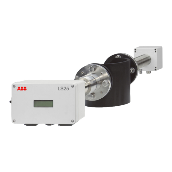
LS25
As an integrated part of the Advance Optima
series the LS25 can be combined with further
analyzer modules and completely operated
remotely in Ethernet networks.
The LS25 has ATEX, IECEx and CSA certificates for
use in for use in hazardous areas.
General purpose and
hazardous areas
Measurement made easy
Additional information
Additional documentation on AO2000-LS25 is
available for download free of charge at
www.abb.com/analytical.
Alternatively simply scan this code:
Advertisement
Table of Contents

Related Manuals for ABB AO2000-LS25


Summary of Contents for ABB AO2000-LS25
- Page 1 — Introduction Additional information LS25 As an integrated part of the Advance Optima Additional documentation on AO2000-LS25 is series the LS25 can be combined with further available for download free of charge at analyzer modules and completely operated www.abb.com/analytical. remotely in Ethernet networks.
-
Page 2: Table Of Contents
AO2000-LS25 LASER ANALYZERS | OI/AO2000-LS25-EN REV. D Table of contents Use in hazardous areas in accordance with CSA .. 22 Safety ................ 4 Introduction ................22 General information and instructions ......... 4 Design ..................22 Warnings .................. 4 CSA certification, gas analyzer ........23 Intended use ................ - Page 3 Span check with flow through cell ........ 80 Connecting a PC ..............49 Span and zero check with internal sealed span cell ..81 Setting the IP address on AO2000-LS25 ......50 14 Decommissioning ........... 81 Setting up the laser analyzer in AO2000 ......50 Temporary shutdown ............81...
-
Page 4: Safety
AO2000-LS25 LASER ANALYZERS | OI/AO2000-LS25-EN REV. D 1 Safety Warnings General information and instructions The warnings in these instructions are structured as follows: These instructions are an important part of the product and must be retained for future reference. DANGER... -
Page 5: Intended Use
AO2000-LS25 LASER ANALYZERS | OI/AO2000-LS25-EN REV. D Intended use Laser analyzer module LS25 is designed for the continuous Sample Smallest range Max. Max. measurement of the concentration of individual components in a components* abs. pressure temperature gas mix. 0 to 0.1 Vol.-% 10 bar 1500 °C... -
Page 6: Improper Use
/ or theft of data or information. Warranty provisions ABB Ltd and its affiliates are not liable for damages and / or losses related to such security breaches, any unauthorized Using the device in a manner that does not fall within the scope... -
Page 7: Use In Potentially Explosive Atmospheres In Accordance With Atex And Iecex
AO2000-LS25 LASER ANALYZERS | OI/AO2000-LS25-EN REV. D 2 Use in potentially explosive atmospheres in accordance with ATEX and IECEx Use in ATEX / IECEx Zone 1 Introduction This part of the Operating Instruction contains information of installation, operation and maintenance of the analyzer, ATEX / IECEx Zone 1 version. -
Page 8: Standards And Directives
AO2000-LS25 LASER ANALYZERS | OI/AO2000-LS25-EN REV. D … 2 Use in potentially explosive atmospheres in accordance with ATEX and IECEx … Use in ATEX / IECEx Zone 1 The analyzer consists of four separate modules: • Transmitter unit with purge fittings and connection box with terminals for the connection of power supply and signal cables as well as optional inputs. -
Page 9: Special Operating Conditions
AO2000-LS25 LASER ANALYZERS | OI/AO2000-LS25-EN REV. D Special operating conditions Device data • The gas analyzer meets Ex approval only with a suitably Laser classification approved purging and monitoring unit for the pressurized Class 1 according to IEC 60825-1 enclosure. •... -
Page 10: Installing The Pressurized Enclosure
AO2000-LS25 LASER ANALYZERS | OI/AO2000-LS25-EN REV. D … 2 Use in potentially explosive atmospheres in accordance with ATEX and IECEx … Use in ATEX / IECEx Zone 1 Installing the pressurized enclosure Purge parameters for pressurized enclosure Installation The purging and monitoring unit must guarantee the following NOTICE purge parameters. - Page 11 AO2000-LS25 LASER ANALYZERS | OI/AO2000-LS25-EN REV. D Pressurized enclosure with nitrogen N WARNING • The purge gas inlet must be connected to the Swagelok® fitting on the receiver unit. Keep gland closest to the Risk of suffocation connection flange free.
- Page 12 AO2000-LS25 LASER ANALYZERS | OI/AO2000-LS25-EN REV. D … 2 Use in potentially explosive atmospheres in accordance with ATEX and IECEx … Use in ATEX / IECEx Zone 1 Housing purge control flow This sequence is presented in Figure 4. The power supply of the gas analyzer is provided via the purging Each state of the system is defined in response to the inputs of and monitoring unit of the housing purging.
-
Page 13: Opening And Closing The Housing
AO2000-LS25 LASER ANALYZERS | OI/AO2000-LS25-EN REV. D Opening and closing the housing This housing contains a 3 V lithium battery. Observe the following safety instructions when opening and closing the housing with the type of protection Ex “p” – pressurized enclosure:... -
Page 14: Use In Atex / Iecex Zone 2
AO2000-LS25 LASER ANALYZERS | OI/AO2000-LS25-EN REV. D … 2 Use in potentially explosive atmospheres in accordance with ATEX and IECEx Use in ATEX / IECEx Zone 2 Introduction This part of the Operating Instruction contains information of installation, operation and maintenance of the analyzer, ATEX Zone 2 version. -
Page 15: Standards And Directives
AO2000-LS25 LASER ANALYZERS | OI/AO2000-LS25-EN REV. D Standards and directives Ex marking All gas analyzer models comply with the regulations of the European Directive 2014/34/EU (ATEX Directive) / IECEx ATEX Marking scheme, and they are manufactured in accordance with the... -
Page 16: Special Operating Conditions
AO2000-LS25 LASER ANALYZERS | OI/AO2000-LS25-EN REV. D … 2 Use in potentially explosive atmospheres in accordance with ATEX and IECEx … Use in ATEX / IECEx Zone 2 Ambient conditions Ex nA nC tc The basic protection type is “n”. This type of protection is... -
Page 17: Electrical Data
AO2000-LS25 LASER ANALYZERS | OI/AO2000-LS25-EN REV. D Electrical data Electrical connections Power supply Safety instructions Power supply unit (input) • The cable glands which are not used must be closed in 85 to 264 V AC, 50 / 60 Hz... -
Page 18: Cable Glands On The Transmitter Unit
AO2000-LS25 LASER ANALYZERS | OI/AO2000-LS25-EN REV. D … 2 Use in potentially explosive atmospheres in accordance with ATEX and IECEx … Electrical connections Cable glands on the transmitter unit During installation, the clamping range for lines as well as the tightening torque of the cable gland and the union nut must be observed. -
Page 19: Cable Connections
AO2000-LS25 LASER ANALYZERS | OI/AO2000-LS25-EN REV. D Cable connections Notes for installation Preliminary remarks • If not pre-assembled at the factory, connect the power cable The transmitter and receiver units are connected with a cable and signal cable to the transmitter unit terminal box, see (signal cable). -
Page 20: Terminal Layout
AO2000-LS25 LASER ANALYZERS | OI/AO2000-LS25-EN REV. D … 2 Use in potentially explosive atmospheres in accordance with ATEX and IECEx … Electrical connections Terminal layout Receiver unit – signal cable Transmitter unit – signal cable to receiver unit Terminal Wire pair... -
Page 21: Operating Instructions
AO2000-LS25 LASER ANALYZERS | OI/AO2000-LS25-EN REV. D Operating instructions Protection against electrostatic discharges DANGER Transmitter unit – service interface (RS232) Risk of explosion! Terminal Signal Remark The painted surface of the device can store electrostatic Data Carrier Detect Connected to terminal 4 charges. -
Page 22: Use In Hazardous Areas In Accordance With Csa
AO2000-LS25 LASER ANALYZERS | OI/AO2000-LS25-EN REV. D 3 Use in hazardous areas in accordance with CSA Introduction This part of the Operating Instruction contains information of installation, operation and maintenance of the analyzer, Class I Division 2 version (CSA approved). -
Page 23: Csa Certification, Gas Analyzer
Storage temperature • Devices for use in potentially explosive atmospheres may −20 °C to +55 °C be serviced and repaired by qualified ABB personnel only. • For measuring devices for potentially explosive IP rating atmospheres, observe the relevant operator guidelines. -
Page 24: Electrical Connections
AO2000-LS25 LASER ANALYZERS | OI/AO2000-LS25-EN REV. D … 3 Use in hazardous areas in accordance with CSA Electrical connections Safety instructions Cable glands (Myers-Hubs) on the transmitter unit Myers hub cable glands • The Myers Hubs cable glands to connect the connection cable for the transmitter and the receiver unit to the terminal box are included with the analyzer. -
Page 25: Cable Connections
AO2000-LS25 LASER ANALYZERS | OI/AO2000-LS25-EN REV. D Cable connections Notes for installation Preliminary remarks • If not pre-assembled at the factory, connect the power cable The transmitter and receiver units are connected with a cable and signal cable to the transmitter unit terminal box, see (signal cable). -
Page 26: Terminal Layout
AO2000-LS25 LASER ANALYZERS | OI/AO2000-LS25-EN REV. D … 3 Use in hazardous areas in accordance with CSA … Electrical connections Terminal layout Receiver unit – signal cable Transmitter unit – signal cable to receiver unit Terminal Wire pair Color Signal... - Page 27 AO2000-LS25 LASER ANALYZERS | OI/AO2000-LS25-EN REV. D Transmitter unit – service interface (RS232) Terminal Signal Remark Data Carrier Detect Connected to terminal 4 Transmit Data — Receive Data — Data Terminal Ready — Ground — Data Set Ready Connected to terminal 4...
-
Page 28: Design And Function
AO2000-LS25 LASER ANALYZERS | OI/AO2000-LS25-EN REV. D 4 Design and function Device description A Device components B Block diagram of the device electronics 1 Transmitter unit 5 Mainboard (Transmitter unit) 2 Receiver unit 6 CPU module (Transmitter unit) 3 Power supply... -
Page 29: Measuring Principle
AO2000-LS25 LASER ANALYZERS | OI/AO2000-LS25-EN REV. D The main board incorporates all electronics required for device operation such as diode laser current and temperature control and analogue-to-digital signal conversion. An LCD continuously shows the concentration of the gas, the laser beam transmission and the device status. -
Page 30: Dimensions, Position Of The Purging Connections And Installation Of Cables
AO2000-LS25 LASER ANALYZERS | OI/AO2000-LS25-EN REV. D … 4 Design and function Dimensions, position of the purging connections and installation of cables (Deviations in explosion-proof designs and compact variants are possible) A Receiver unit 1 Purge gas outlet (housing purging), ∅ 6 mm 6 Purge gas inlet (flange purging), ∅... -
Page 31: Software
Laser classes according to IEC 60825-1 n Production number 8 Warning: laser class 1 • Laser Class 1M for sample component O • Laser Class 1 for all other sample components Figure 13: Name plate AO2000-LS25 (example, ATEX / IECEx version, Zone 1) -
Page 32: Scope Of Delivery
6 Warning: do not open while m Production number energized. 7 Warning – Risk of explosion: de- energize before opening. Figure 15: Name plate AO2000-LS25 Compact (example, ATEX / IECEx Zone 2) Receiver unit 1 Manufacturer 8 Sample component Scope of delivery... -
Page 33: Transport And Storage
All claims for damages must be submitted to the shipper disposal or must observe the following regulations for shipping without delay and before installation. purposes: All devices delivered to ABB must be free from any hazardous Transporting the device materials (acids, alkalis, solvents, etc.). Observe the following instructions: Address for the return: •... -
Page 34: Installation
AO2000-LS25 LASER ANALYZERS | OI/AO2000-LS25-EN REV. D 7 Installation Safety instructions WARNING Installation of the measuring instrument Both the transmitter and receiver units should be easily Risk of injury due to process conditions. accessible. A person should be able to stand in front of either the... -
Page 35: Necessary Tools And Other Equipment
AO2000-LS25 LASER ANALYZERS | OI/AO2000-LS25-EN REV. D Flange type DN 50 40 mm DN 80 55 mm Figure 19: Flange line-up tolerances A Flange without valve B Flange with valve After correct adjustment and line-up of the device the maximum... -
Page 36: Mounting
AO2000-LS25 LASER ANALYZERS | OI/AO2000-LS25-EN REV. D … 7 Installation Mounting A Transmitter unit 6 Purge gas inlet B Receiver unit 7 Span cell inlet (non-corrosive gases, see also Validation on page 80) 1 Transmitter unit and housing electronics 8 Receiver electronics and housing... -
Page 37: Air Purging Of Flanges
AO2000-LS25 LASER ANALYZERS | OI/AO2000-LS25-EN REV. D 4. Attach an O-ring (ungreased) to the adapter ring and mount Air purging of flanges the transmitter unit to the balancing device. The guiding pin The instrument windows are kept clean by setting up a positive on the adapter ring must fit the hole in the transmitter unit flow of air through the flanges and into the stack. -
Page 38: Housing Purging Of The Transmitter And Receiver Units
Figure 21: Isolation flange (Example) inside the units. For toxic gas and highly corrosive applications especially in ABB recommends reducing the purge gas flow to less than combination with high pressure the first flange has to be an 0.5 l/min. -
Page 39: Electrical Connections
AO2000-LS25 LASER ANALYZERS | OI/AO2000-LS25-EN REV. D 8 Electrical connections Safety instructions Transmitter unit interface WARNING Risk of injury due to live parts. Improper work on the electrical connections can result in electric shock. • Connect the device only with the power supply switched off. -
Page 40: Terminal Assignment
AO2000-LS25 LASER ANALYZERS | OI/AO2000-LS25-EN REV. D … 8 Electrical connections Terminal assignment Signal cable Devices with Phoenix connectors Table 21 shows the connection assignment of the signal cable Signal Description connectors. Lineup Alignment voltage RU Temp Signal from embedded receiver temperature sensor... -
Page 41: Power Supply / Analog Inputs
AO2000-LS25 LASER ANALYZERS | OI/AO2000-LS25-EN REV. D Power supply / analog inputs Service interface (RS232) Table 24 shows the connection assignment of the power supply connectors and the analog inputs (4 to 20 mA). This connection Terminal Signal Comments assignment applies only to the connector on the cable for the... -
Page 42: Ethernet Connection To Ao2000
AO2000-LS25 LASER ANALYZERS | OI/AO2000-LS25-EN REV. D … 8 Electrical connections Ethernet connection to AO2000 The transmitter unit is connected to the AO2000 central unit via an Ethernet cable (for outdoor use, acid and UV resistant). Note The LS25 Ethernet port is switched off when the LS25 service interface is in use. - Page 43 AO2000-LS25 LASER ANALYZERS | OI/AO2000-LS25-EN REV. D AO2000 with two or three laser analyzers 1 Customer network 3 Network cable (standard) 2 Ethernet switch Figure 25: Ethernet connection – AO2000 with two or three laser analyzers The laser analyzers are connected to a switch which is connected to the 2nd Ethernet interface -X08 via its uplink port.
-
Page 44: Connecting The Power Supply
• If some LEDs are lit and others are not, note the status of 3. Connect and screw the connectors to the power supply. the LEDs and contact ABB Service. The main board may need to be replaced. Description Table 27: Pin assignment input 100 to 240 V AC Description GND (−) -
Page 45: Connecting Analog Inputs (Option)
AO2000-LS25 LASER ANALYZERS | OI/AO2000-LS25-EN REV. D Connecting analog inputs (option) Note Active (with separate power supply) or passive (power supply from the LS25) sensors can be connected. • The connection examples show the connection of a temperature sensor. Pressure and flow sensors are connected to the corresponding inputs (Press / Flow). -
Page 46: Commissioning
AO2000-LS25 LASER ANALYZERS | OI/AO2000-LS25-EN REV. D 9 Commissioning Introduction Having completed the installation of the transmitter and receiver according to the previous sections the analyzer is ready for start-up. The start-up of the system consists of 3 main activities: 1. -
Page 47: Align Analyzer With Laser Alignment Device
AO2000-LS25 LASER ANALYZERS | OI/AO2000-LS25-EN REV. D Align analyzer with laser alignment device 1 Laser pointer 4 Focusing screen 2 Adapter ring 5 Fixing screws M16 (adjusting screws) 3 Purging flange 6 Stud screws (locking screws) Figure 32: Installing the laser alignment tool and aligning the flanges... -
Page 48: Pre-Aligning The Purging Flanges
AO2000-LS25 LASER ANALYZERS | OI/AO2000-LS25-EN REV. D … 9 Commissioning … Align analyzer with laser alignment Setting the maximum transmission device Fine-tuning of the transmitter and receiver units is performed by measuring the adjustment voltage at the connectors of the... -
Page 49: Connecting A Pc
AO2000-LS25 LASER ANALYZERS | OI/AO2000-LS25-EN REV. D Connecting a PC The software for service communication with the analyzer is supplied with the instrument and will run under Microsoft The fine-tuning procedure is as follows: Windows®. The software does not require any installation. -
Page 50: Setting The Ip Address On Ao2000-Ls25
AO2000-LS25 LASER ANALYZERS | OI/AO2000-LS25-EN REV. D … 9 Commissioning Setting the IP address on AO2000-LS25 Setting up the laser analyzer in AO2000 1. Call up the “MENU / Configure / System / Setup system modules” menu and press the <NEW> key. -
Page 51: Configuration, Parameterization
AO2000-LS25 LASER ANALYZERS | OI/AO2000-LS25-EN REV. D 10 Configuration, parameterization Parameterization of the device 4. Enter the IP address of the laser analyzer and press <ENTER> The instrument calculates the gas concentration from the to confirm. The factory-set IP address is 192.168.1.237. -
Page 52: Software Start-Up
A password is only required for Advanced mode that enables full access to all the instrument setting parameters. Extended mode should be used during service adjustment of the device. For the necessary password, please contact ABB Service. Figure 35: Interface selection <Demo mode> (Demo mode) -
Page 53: Description Of Menus And Parameters
AO2000-LS25 LASER ANALYZERS | OI/AO2000-LS25-EN REV. D Description of menus and parameters Main menu After pressing the <User mode> button the program opens the The parameters are explained in detail below: Status: “Measurements” menu. The example below is for a device measuring oxygen. - Page 54 AO2000-LS25 LASER ANALYZERS | OI/AO2000-LS25-EN REV. D … 10 Configuration, parameterization … Description of menus and parameters Line position: Gas Pressure (Bar abs.): The position of the line peak (maximum absorption) in samples The current absolute pressure used to calculate the gas of the AD converter [0–63].
-
Page 55: Plot Readings
AO2000-LS25 LASER ANALYZERS | OI/AO2000-LS25-EN REV. D Peltier pump (A): Second harmonic signal <Second harmonic signal> The current drawn by the Peltier element. <Second harmonic signal> displays signals recorded by the device for calculation of the gas concentration. Modulation ampl. (V): Amplitude of the high frequency modulation voltage to the laser. -
Page 56: Log Readings
AO2000-LS25 LASER ANALYZERS | OI/AO2000-LS25-EN REV. D … 10 Configuration, parameterization … Description of menus and parameters The line position must be within the acceptance window marked The sampling period (logging interval), file directory, and the by the two vertical red lines. For some instruments such as dual filename are user defined (default filename is gas instruments more than one absorption line is plotted. -
Page 57: View Error Log
<Rewind system log 100 lines> and subsequently <Save system log>. In case of instrument failure it is always useful to download the error log and the system log and send both files to ABB for diagnostics. Figure 39: Menu “Config”, page 1... - Page 58 AO2000-LS25 LASER ANALYZERS | OI/AO2000-LS25-EN REV. D … 10 Configuration, parameterization … Description of menus and parameters Gas pressure and temperature Pressure and temperature input method The strength of the absorption line and line width are pressure The <Pressure/Temperature input method> specifies whether and temperature dependent.
- Page 59 AO2000-LS25 LASER ANALYZERS | OI/AO2000-LS25-EN REV. D Optical path through gas (m) Optical path through RU & TU (m) The optical path through the transmitter and receiver units (TU + RU). This is the internal optical path of the instrument.
- Page 60 AO2000-LS25 LASER ANALYZERS | OI/AO2000-LS25-EN REV. D … 10 Configuration, parameterization … Description of menus and parameters Line width averaging: Specifies the number of line width averaging. Line width adaptive averaging: Switched OFF = the rolling average (as for concentration) applies.
-
Page 61: Gas Specific Parameters
AO2000-LS25 LASER ANALYZERS | OI/AO2000-LS25-EN REV. D Input methods for H Gas specific parameters <Gas specific parameters> The following input methods for the H O concentration are If the instrument monitors more than one absorption line a available: selection menu with the relevant gases appears first. - Page 62 AO2000-LS25 LASER ANALYZERS | OI/AO2000-LS25-EN REV. D … 10 Configuration, parameterization … Description of menus and parameters Some more specific units are also available such as %*m, ppm*m Min/Max line position [0-63] and ppb*m. These units are often used for open path analyzers...
-
Page 63: Calibrating The Device
There are two available calibration modes: “PROPORTIONAL” and “GLOBAL”, which can be toggled. Note In this case, after such a calibration ABB is relieved of Calibration mode “Proportional” responsibility for correct device calibration in the specified The default calibration mode is “PROPORTIONAL”. In this mode range of gas temperature and pressure. -
Page 64: Tcp/Ip And Modem Configuration
AO2000-LS25 LASER ANALYZERS | OI/AO2000-LS25-EN REV. D … 10 Configuration, parameterization … Description of menus and parameters TCP/IP and modem configuration <TCP/IP & modem Calibration mode “Global” configuration> In the “GLOBAL” calibration mode the device performs reference TCP/IP parameters of the embedded Ethernet board and the measurements of the absorption line width in addition to the initializing string of a modem can be configured in this menu. -
Page 65: File Download / Upload
The filenames can be edited. The menu allows to save/restore device data to/from file. ABB recommends using the file extension .rea or .dmp for the device views and .set or .stt for the device settings. If an existing file name is chosen the new data are appended to this file. -
Page 66: Manual Instrument Control
AO2000-LS25 LASER ANALYZERS | OI/AO2000-LS25-EN REV. D … 10 Configuration, parameterization … Description of menus and parameters <Manual instrument control> Enter Sleep mode The instrument will be forced into Sleep mode. Reset Microcontroller Microcontroller is reset. Collect AD statistics For service purpose only. -
Page 67: Configuration Via Ao2000 Central Unit
AO2000-LS25 LASER ANALYZERS | OI/AO2000-LS25-EN REV. D Configuration via AO2000 central unit Those parameters which are used to fit the laser analyzer to the measuring point can also be configured via the AO2000 display and control unit. This configuration method has the same effect as that using the service software. -
Page 68: Operation
AO2000-LS25 LASER ANALYZERS | OI/AO2000-LS25-EN REV. D 11 Operation Safety instructions Measuring mode If there is a chance that safe operation is no longer possible, take the device out of operation and secure it against While the operating mode is «measuring», the device can be in unintended startup. - Page 69 AO2000-LS25 LASER ANALYZERS | OI/AO2000-LS25-EN REV. D Mode «Zero» / «Span» Zero (Zero) and span check (Span) functionality are optional features of the analyzer. Refer to Calibrating the device <Calibrate instrument> on page 63. Fault mode «Instrument Off» Fault mode is entered when the device has detected a severe failure during the self-test or normal operation, which might permanently damage the device.
-
Page 70: Diagnosis / Troubleshooting
AO2000-LS25 LASER ANALYZERS | OI/AO2000-LS25-EN REV. D 12 Diagnosis / Troubleshooting Error messages During operation essential status information about the device is displayed on the LCD mounted in the transmitter / AO2000 main unit. The instrument messages and their possible explanations and actions to be taken are given in the table below. - Page 71 AO2000-LS25 LASER ANALYZERS | OI/AO2000-LS25-EN REV. D Fault message Explanations and actions Troubleshooting instructions Low laser temp. ERROR Allow the transmitter unit to cool. High laser temp. The laser temperature regulation has failed and the laser is too cold/warm. Improve ventilation, provide heat shielding if The instrument has entered FAULT mode and attempts automatic restart after necessary.
-
Page 72: Error Messages At The Ao2000 Central Unit
AO2000-LS25 LASER ANALYZERS | OI/AO2000-LS25-EN REV. D … 12 Diagnosis / Troubleshooting … Error messages Error messages at the AO2000 central unit Text Corresponds to LCD error message The LS25 analyzer has a global error. The LS25 analyzer has a maintenance request. -
Page 73: Maintenance
AO2000-LS25 LASER ANALYZERS | OI/AO2000-LS25-EN REV. D 13 Maintenance Safety instructions DANGER Use in Potentially Explosive Atmospheres The inspection and maintenance of the explosion-protected Risk of explosion if the device is operated with the housing version of the gas analyzer requires special knowledge. -
Page 74: Introduction
There is a risk of explosion if the housing is opened in a hazardous atmosphere. Maintenance plan Before opening the housing: ABB gas monitors have no moving parts and require no • A valid fire permit must be present. consumables. -
Page 75: Cleaning Of Optical Windows
AO2000-LS25 LASER ANALYZERS | OI/AO2000-LS25-EN REV. D Optimizing purging gas flow of the flanges Cleaning of optical windows It is generally difficult to give a recommendation of what purge gas quantity is needed for certain applications. The required Dust, soot or other contamination on the optical windows will purge gas volume depends on the flow velocity of the gas in the reduce the signal level. -
Page 76: Calibration Of The Device
– If the ratios are equal the flanges are completely filled with purge gas. ABB recommends verifying calibration of the device once a year – If the gas-ratio is less than the length-ratio the using a certified sample gas and the supplied calibration cell. -
Page 77: Calibration Instructions
To obtain the optimal signal-to-noise ratio with one of the • When gas is flushed through the cell, the cell pressure is optional calibration cells (accessory available from ABB), the gas higher than the ambient pressure. The pressure difference concentrations in Table Recommended gas concentrations for... -
Page 78: Performing The Calibration
AO2000-LS25 LASER ANALYZERS | OI/AO2000-LS25-EN REV. D … 13 Maintenance … Calibration of the device Performing the calibration WARNING Perform the following steps to verify and calibrate: 1. Remove the transmitter and receiver units at the Risk of injury due to process conditions. -
Page 79: Proportional And Global Calibration
AO2000-LS25 LASER ANALYZERS | OI/AO2000-LS25-EN REV. D PROPORTIONAL and GLOBAL calibration Line broadening compensation requires a large number of Use GLOBAL calibration: parameters to be measured. These parameters are critical for • If spectral properties of the laser seem to have drifted. -
Page 80: Validation
AO2000-LS25 LASER ANALYZERS | OI/AO2000-LS25-EN REV. D … 13 Maintenance Validation The AO2000-LS25 analyzer may be fitted with different options The default concentration relates to a optical path length of 1 m. to carry out span and zero checks for validation on the process. -
Page 81: Span And Zero Check With Internal Sealed Span Cell
By default the internal span cell is calibrated to give a 75 to 80 % of full-scale reading. (Alternative calibration is possible, contact ABB or your local distributor.) -
Page 82: Dismounting And Disposal
AO2000-LS25 LASER ANALYZERS | OI/AO2000-LS25-EN REV. D 15 Dismounting and disposal Disposal Dismounting WARNING Note Products that are marked with the adjacent symbol Risk of injury due to process conditions. may not be disposed of as unsorted municipal waste The process conditions, for example high pressures and (domestic waste). -
Page 83: Specification
AO2000-LS25 LASER ANALYZERS | OI/AO2000-LS25-EN REV. D 16 Specification Note The device data sheet is available in the ABB download area at www.abb.com/analytical. 17 Additional documents Note All documentation, declarations of conformity and certificates are available in ABB's download area. -
Page 84: Appendix
AO2000-LS25 LASER ANALYZERS | OI/AO2000-LS25-EN REV. D 18 Appendix Return form Statement on the contamination of devices and components Repair and/or maintenance work will only be performed on devices and components if a statement form has been completed and submitted. - Page 85 AO2000-LS25 LASER ANALYZERS | OI/AO2000-LS25-EN REV. D Notes...
- Page 86 AO2000-LS25 LASER ANALYZERS | OI/AO2000-LS25-EN REV. D Notes...
- Page 87 AO2000-LS25 LASER ANALYZERS | OI/AO2000-LS25-EN REV. D Notes...
- Page 88 We reserve the right to make technical changes or modify the contents of this document without prior notice. With regard to purchase orders, the agreed particulars shall prevail. ABB does not accept any responsibility whatsoever for potential errors or possible lack of information in this document.