Table of Contents
Advertisement
Quick Links
Advertisement
Table of Contents

Related Manuals for ABB LGR-ICOS GLA531 Series


Summary of Contents for ABB LGR-ICOS GLA531 Series
- Page 1 GLA531 Series LGR-ICOS Analyzer Operating Manual ABB Inc. Measurement & Analytics 3400, rue Pierre-Ardouin Quebec, (Quebec) G1P 0B2 Canada Tel: 1 800 858 3847 (North America) Tel: +1 418 877 2944 (Worldwide) Fax: +1 418 877 2834 abb.com/analytical 3KXG165002R4201_2021_04...
-
Page 2: Table Of Contents
Service Screen ..............................33 Shutting Down the Analyzer ..........................34 Communications – Data and Alarms ....................35 Input/Output Interface Hardware ......................... 35 Ethernet ................................36 Modbus/TCP ................................. 36 USB Drive – Local Data Access .......................... 38 3KXG165002R4201_2021_04 ABB PROPRIETARY INFORMATION... - Page 3 Basic Troubleshooting in ICOS Gas Measurements ................. 68 Gas Temperature ..............................68 Gas Pressure................................ 68 Laser Linelock and Self-Correction ........................68 Laser Path-Length and Astigmatic Mirrors ......................69 Hardware Failures ..............................70 Purge System ............................... 71 3KXG165002R4201_2021_04 ABB PROPRIETARY INFORMATION...
-
Page 4: Disclaimers
ABB reserves the right to make changes to the specifications of all equipment and software, and to the contents of this document, without obligation to notify any person or organization of such changes. Every effort has been made to ensure that the information contained in this document is current and accurate. -
Page 5: Customer Support
Operating Manual Gas Analyzer Customer Support ABB provides product support services worldwide. To receive product support, either in or out of warranty, contact the ABB office that serves your geographical area, or the address indicated below: ABB Inc. Measurement & Analytics... -
Page 6: Introduction
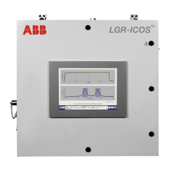
Operating Manual 1 Introduction This document is a universal user manual for operating ABB GLA531 Series LGR-ICOS™ Gas Analyzer. It also provides information on the operational safety, maintenance, troubleshooting, and calibrations. This manual describes a fully loaded analyzer with all options. Your analyzer may or may not have all the options available. -
Page 7: General Safety
Symbols Meaning Emphasizes facts and conditions important to analyzer operation. NOTE or IMPORTANT! General warning or caution. Gives general safety information that must be followed to avoid hazardous conditions. WARNING! Laser warning: potential laser hazards WARNING! 3KXG165002R4201_2021_04 ABB PROPRIETARY INFORMATION... -
Page 8: Laser Product Class
This analyzer is a Class 1 laser product. NOTE The ABB GLA531 Series LGR-ICOS™ Gas Analyzer is a Class 1 laser product when the front panel is closed. Electrical Safety and Fuse Electrical insulations and the analyzer enclosure protect operators from contact with hazardous voltages during normal system operations. -
Page 9: Certifications And Compliances
GLA531 Series LGR-ICOS™ Gas Analyzer Operating Manual Certifications and Compliances The ABB GLA531 Series LGR-ICOS™ Gas Analyzer offers the following certifications in Table 2 for hazardous-location installations, flammable gas, and fire hazards. An example of a certification plate is shown in Figure 1. - Page 10 This General-Purpose analyzer complies with European CE Directives and 21 CFR Laser Safety Regulations as listed above in Table 2. Figure 1 Example of a Certification Plate for an Analyzer with X-Purge Protection System 3KXG165002R4201_2021_04 ABB PROPRIETARY INFORMATION...
-
Page 11: Operator Safety
Do not operate the analyzer with the front panel open: · The front panel protects against electrical shock and accidental laser exposure to operators. ABB GLA531 Series LGR-ICOS · Gas Analyzers with the purged-and-pressurized protection system for flammable gas are designed to: 1) maintain a specific internal pressurization, 2) continuously dilute the atmosphere inside the enclosure to prevent any ignitions, and 3) prevent fire and explosion hazards. -
Page 12: Purge
Allow the system to cool down before performing any maintenance work. Burn hazards may be present during replacement or service of the ICOS WARNING! heaters, filters, thermocouples, and solenoid valves. Figure 2 Burn Hazard Label and Location 3KXG165002R4201_2021_04 ABB PROPRIETARY INFORMATION... -
Page 13: Laser Hazards
Operating Manual Laser Hazards Up to two lasers are used in the ABB GLA531 Series LGR-ICOS™ Gas Analyzer The laser wavelength depends on the species of gas measured. Under normal operation, with the analyzer front panel closed, the spectroscopy device is a Class 1 Laser Product in accordance with Title 21 Code of Federal Regulations, chapter 1, sub-chapter J. -
Page 14: Fire Safety Provisions
This label is located on the external right side panel of the enclosure. Figure 5 Pinch Point Label This label is located on the ICOS-Module covers (near the latch snaps), and on the right side panel of the enclosure (near the door closing position). 3KXG165002R4201_2021_04 ABB PROPRIETARY INFORMATION... - Page 15 These labels are located on the ICOS-Module covers (see Figure 3). Figure 8 Burn Hazard Label This label is located on the ICOS Module cover. Figure 9 Fire Hazard Label Warning for the cleaning solvents used for cleaning the ICOS optical mirror. 3KXG165002R4201_2021_04 ABB PROPRIETARY INFORMATION...
-
Page 16: Weee Directive
Operating Manual WEEE Directive The ABB GLA531 Series LGR-ICOS™ Gas Analyzer is not subjected to WEEE Directive 2002/96/EC (Waste Electrical and Electronic Equipment) or relevant national laws (for example, ElektroG in Germany). The product must be disposed of at a specialized recycling facility. Do not use municipal garbage collection points. -
Page 17: Features And Theory Of Icos
GLA531 Series LGR-ICOS™ Gas Analyzer Operating Manual 3 Features and Theory of ICOS The ABB GLA531 Series LGR-ICOS™ Gas Analyzer is a laser-based spectroscopy instrument. The LGR- cavity design enhances the detection of laser light absorption by the targeted gas molecules. The ICOS enhancement improves the signal-to-noise ratio over conventional laser sensors, enabling robust measurements and precise monitoring of trace gases. - Page 18 This equation determines gas concentrations, even in hostile environments, without using calibration gases or reference standards. The values measured are: · Mixtures containing several species · Flows at elevated temperatures and pressures Figure 11 Typical Laser Absorption Spectroscopy Setup 3KXG165002R4201_2021_04 ABB PROPRIETARY INFORMATION...
-
Page 19: Lgr's Oa-Icos
The measured absorption spectra is recorded and used to determine a quantitative measurement of mixing ratio directly and without external calibration when combined with the recorded: ü Measured gas temperature and pressure in the cell ü Effective path length ü Known line strength Figure 12 OA-ICOS Analyzer Schematic Diagram 3KXG165002R4201_2021_04 ABB PROPRIETARY INFORMATION... -
Page 20: User Interface Operation
1) tap the desired button on the touchscreen, or 2) use a keyboard/mouse to move the pointer to the desired button, then click the button. Avoid alternating between the mouse and touchscreen for zoom control. Touchscreen functionality should primarily be used for visualization of trends, NOTE values, and alarms. 3KXG165002R4201_2021_04 ABB PROPRIETARY INFORMATION... -
Page 21: Display
(%), parts per million (ppm), or possibly in parts per billion (ppb). Figure 16 is an example of a numeric display that shows measurements of four different gases. Figure 16 Numeric Display 3KXG165002R4201_2021_04 ABB PROPRIETARY INFORMATION... -
Page 22: Spectrum Display
Detected light absorptions of the targeted gases shown as small dips on the Detector Voltage chart · Absorbance signal intensity of the targeted gases shown as peaks on the Absorbance chart (bottom) · Laser frequency linelock at the center of each absorbance window Figure 17 Spectrum Display 3KXG165002R4201_2021_04 ABB PROPRIETARY INFORMATION... -
Page 23: Time-Chart Display
(see Figure 20). The solid black line on the plot is a running average of the last 10 data points. Figure 18 Time-chart Display 3KXG165002R4201_2021_04 ABB PROPRIETARY INFORMATION... -
Page 24: Alarm Status Display
Red indicates there is a problem, and maintenance is immediately required. Error messages for each alarm can be displayed by selecting the relevant alarm button: after the button is selected, a pop-up window appears displaying the messages. Figure 19 Alarm Status Display 3KXG165002R4201_2021_04 ABB PROPRIETARY INFORMATION... -
Page 25: Rate Button
To access the archive files, click the archive folder. To go back to the previous screen, click the arrow pointing up to the right of the file path line /home/lgr/data/archive. Data files are written in text format (ASCII) and contain labeled columns that show: 3KXG165002R4201_2021_04 ABB PROPRIETARY INFORMATION... -
Page 26: File Transfer
STEP 5 After the file transfer is complete, click Unmount USB to stop communication with the USB memory stick. STEP 6 Remove the USB memory stick. STEP 7 Click Close to exit the File Transfer screen. To delete files, highlight the file to delete and click Delete. NOTE 3KXG165002R4201_2021_04 ABB PROPRIETARY INFORMATION... -
Page 27: Setup Button
Calibration: single-point calibration using a known reference standard · Laser Adjust: manually fine-tune laser wavelength for goodness of fit (GOF) if necessary · 4–20 mA: set the scale for concentration-to-mA conversion · Service: only accessible by ABB service personnel 3KXG165002R4201_2021_04 ABB PROPRIETARY INFORMATION... -
Page 28: Time/Files
Use the Clock area to adjust the current time and date for the analyzer (see Figure 24). The time zone and daylight savings enable/disable feature are also set on this screen. Available time-stamp formats are listed in Table 3 below. 3KXG165002R4201_2021_04 ABB PROPRIETARY INFORMATION... - Page 29 Time Stamp Name Format mm/dd/yyyy, Absolute Local American hh:mm:ss.sss dd/mm/yyyy, Absolute Local European hh:mm:ss.sss mm/dd/yyyy, Absolute GMT American hh:mm:ss.sss dd/mm/yyyy, Absolute GMT European hh:mm:ss.sss Relative Seconds After Power On ssssss.sss Relative Seconds in Hours, Minutes, Seconds hh:mm:ss.sss 3KXG165002R4201_2021_04 ABB PROPRIETARY INFORMATION...
-
Page 30: Calibration
STEP 5 Repeat STEP 2 through STEP 4 for all gases measured by the analyzer. STEP 6 After the calibration is complete, click OK. The analyzer will then resume its normal measurement mode. STEP 7 Click Close to exit the Calibration screen. Figure 25 Calibration Tab 3KXG165002R4201_2021_04 ABB PROPRIETARY INFORMATION... -
Page 31: Laser Adjust
Click Close to exit the Laser Adjust screen. Figure 26 shows a Laser Adjust screen with the laser frequencies properly adjusted, so that the absorption features are centered on the target lines. Figure 26 Laser Adjust Tab 3KXG165002R4201_2021_04 ABB PROPRIETARY INFORMATION... -
Page 32: Ma Range Adjustment
STEP 1 Click Setup, then the 4-20 mA tab. STEP 2 Enter the maximum value in the gas concentration range for each channel, as shown in Figure 28. STEP 3 Click Close to exit the 4–20 mA screen. 3KXG165002R4201_2021_04 ABB PROPRIETARY INFORMATION... -
Page 33: Service Screen
Operating Manual Figure 28 4-20 mA Analog Output Adjustment Service Screen The Service screen is password protected and only accessible to ABB-trained field service personnel. Only authorized personnel may open the analyzer to perform internal maintenance. Follow the “Lockout-tagout” procedure when servicing the analyzer. -
Page 34: Shutting Down The Analyzer
To properly shut down the analyzer, perform a soft shutdown by first selecting the Exit button on the Control Bar. When the dialog box appears with the question, “Do you wish to shutdown?” (see Figure 29), select OK. Figure 29 Shut Down Analyzer 3KXG165002R4201_2021_04 ABB PROPRIETARY INFORMATION... -
Page 35: Communications - Data And Alarms
100 m (328 ft) for 100BaseTX Maximum network length 200 m (656 ft) with one repeater EIA/TIA-568 TSB or EIA-TIA-568 compliant Category 6 SF(Shielded Foil) cable, or 150 ohm STP MII cable in metallic conduit, may be used as alternates 3KXG165002R4201_2021_04 ABB PROPRIETARY INFORMATION... -
Page 36: Ethernet
NOTE Ethernet The ABB GLA531 Series LGR-ICOS™ Gas Analyzer runs on the UNIX operating system. Data files stored on the internal hard drive of the analyzer can be accessed via a Windows Share Drive over a local area network (LAN) Ethernet connection. For the Ethernet feature to work, the analyzer must: ·... - Page 37 Each channel is output on two registers with different formats · Registers 1 - 8 are integers where 32767 is the full scale (FS) · Registers 9 - 24 are floating point with the least-significant bit first (LSBF) 3KXG165002R4201_2021_04 ABB PROPRIETARY INFORMATION...
-
Page 38: Usb Drive - Local Data Access
USB Drive – Local Data Access The ABB GLA531 Series LGR-ICOS™ Gas Analyzer supports up to USB 2.0. Refer to the File Transfer section (also, see Figure 22) for instructions on transferring data from the analyzer to a USB 2.0 memory stick. -
Page 39: Ma Isolated Analog Outputs
Figure 32. Two single-ended connections, CH5 and CH6, are the connection points for the 4-20 mA warming/alarm monitors. Figure 32 CH5 Temperature and CH6 Analyzer Warning/Alarm Screw-Terminal Connections Table 8 and Table 9 provide the current outputs in milliamps (mA) and their corresponding warning/alarm description in the analyzer. 3KXG165002R4201_2021_04 ABB PROPRIETARY INFORMATION... - Page 40 Not a Number (NaN). Faulty random Warning 17 ± 0.1 NaN reading number/character result being displayed Inlet tubing temperature is above or below Warning 18 ± 0.1 Inlet Tubing temperature normal No issue 20 ± 0.1 No warning/alarm 3KXG165002R4201_2021_04 ABB PROPRIETARY INFORMATION...
- Page 41 CH5 and CH6 start porting 20 mA values. An analyzer not equipped with a gas-expansion heater, orifice heater, or NOTE inlet-tube heater, does not have the associated color flags in the Alarm Status display screen. 3KXG165002R4201_2021_04 ABB PROPRIETARY INFORMATION...
-
Page 42: Purged-And-Pressurized Protection System For Flammable Gas
The lower limit is usually defined as Lower Flammability Limit (LFL). Each flammable gas has a different level of LFL, as shown in the LFL row in Table 10 below. The protection system of ABB GLA531 Series LGR-ICOS™ Gas Analyzer maintains a dilution ratio below 25% of LFL for each specific flammable gas, to ensure safety. -
Page 43: Protection System Types For Analyzers
10. If there is a large leak of flammable gas inside an enclosure, the purge air-flow rate must be sufficient to dilute the maximum intake of the flammable gas below 25% of its lower flammability limit (LFL). The ABB GLA531 Series LGR-ICOS™ Gas Analyzer offers two types of protection systems. Both are certified designs for installations in hazardous locations for flammable-gases: ·... - Page 44 GLA531 Series LGR-ICOS™ Gas Analyzer Operating Manual Figure 33 GLA531 Series Configuration Comparison: Z-Purge Type (Left) and X-Purge Type (Right) 3KXG165002R4201_2021_04 ABB PROPRIETARY INFORMATION...
-
Page 45: X-Purge Type Protection System
(see Figure 34). An X-Purge controller receives AC power only, and the voltage input is set at the ABB factory. Refer to the certification plate on the right side panel of the enclosure for the input voltage. ü The circuit diagrams in Figure 35 (CDA purge) and Figure 37 (N... - Page 46 GLA531 Series LGR-ICOS™ Gas Analyzer Operating Manual Figure 35 X-Purge CDA Controller Circuit Diagram for Power Interlock Figure 36 X-Purge CDA Flow Diagram for Pressurization System and Power Interlock 3KXG165002R4201_2021_04 ABB PROPRIETARY INFORMATION...
- Page 47 GLA531 Series LGR-ICOS™ Gas Analyzer Operating Manual Figure 37 X-Purge N Controller Circuit Diagram for Power Interlock Figure 38 X-Purge N Flow Diagram for Pressurization System and Power Interlock 3KXG165002R4201_2021_04 ABB PROPRIETARY INFORMATION...
- Page 48 OPEN OPEN OPEN OPEN CLOSED OPEN CLOSED OPEN OPEN CLOSED CLOSED OPEN OPEN OPEN OPEN OPEN CLOSED OPEN OPEN OPEN OPEN OPEN CLOSED OPEN OPEN OPEN OPEN OPEN CLOSED OPEN CLOSED OPEN OPEN CLOSED CLOSED CLOSED 3KXG165002R4201_2021_04 ABB PROPRIETARY INFORMATION...
-
Page 49: Z-Purge Type Protection System
The circuit diagrams in Figure 39 (CDA purge) and Figure 41 (N purge), and the purge flow diagrams in Figure 40 (CDA purge) and Figure 42 (N purge) illustrate the design of the Z-type simple pressurization system and purge alarm. 3KXG165002R4201_2021_04 ABB PROPRIETARY INFORMATION... - Page 50 GLA531 Series LGR-ICOS™ Gas Analyzer Operating Manual Figure 39 Z-Purge CDA Circuit Diagram for Simple Pressurization and Alarm Figure 40 Z-Purge CDA Flow Diagram for Simple Pressurization and Alarm 3KXG165002R4201_2021_04 ABB PROPRIETARY INFORMATION...
- Page 51 GLA531 Series LGR-ICOS™ Gas Analyzer Operating Manual Figure 41 Z-Purge N Circuit Diagram for Simple Pressurization and Alarm 3KXG165002R4201_2021_04 ABB PROPRIETARY INFORMATION...
- Page 52 Fire safety, explosion hazards, and hazardous area zoning must be assessed accordingly. Regular inspection and proper maintenance of the analyzer and its protective enclosure must be performed based on the facility requirements and national regulations. 3KXG165002R4201_2021_04 ABB PROPRIETARY INFORMATION...
- Page 53 GLA531 Series LGR-ICOS™ Gas Analyzer Operating Manual Failure to maintain the protective enclosure for keeping the sufficient Lower Flammability Limit (LFL) during analyzer operations may cause serious injury or death from unexpected fire and explosion hazards. DANGER! 3KXG165002R4201_2021_04 ABB PROPRIETARY INFORMATION...
-
Page 54: Analyzer Hardware
Figure 43 Analyzer Hardware Layout Only authorized personnel may perform repairs of the internal hardware. Follow the “Lockout-tagout” procedure when servicing the analyzer. It is recommended that ABB field service personnel perform all repairs and WARNING! preventive maintenance (PM) services to the analyzer. -
Page 55: Replaceable Hardware
950-0000-9040-0000 Screw Terminal Plug, 4 POS 5.08 mm Green 950-0000-9003-0000 Fuse, 5 A, 250 V (five-pack) 950-0000-9008-0000 Fan 60x60x10mm, 12 VDC Brushless, 0.96 W, 15.5 cfm 950-0000-9007-0000 Fan 80x80x25mm, 12 VDC Brushless, 1.70 W, 41 cfm 3KXG165002R4201_2021_04 ABB PROPRIETARY INFORMATION... -
Page 56: Ac-To-Dc 24 V Power Supply Converter
DC outputs. Each DC voltage output wire is color coded as listed in Table 14 below. Table 14 Wire Color to DC Voltage Association Wire Color DC Voltage Black Common +5 volts Green +12 volts Purple +12 volts Blue +15 or +24 volts White –12 volts Orange –15 or –24 volts 3KXG165002R4201_2021_04 ABB PROPRIETARY INFORMATION... -
Page 57: Temperature Controller
The SSR for the heaters receive their enable/disable commands from the temperature controllers. The SSR for the exhaust pump receives the control signal from the two-port solenoid driver on channel 2. When an SSR is enabled (energized), the green LED on top illuminates. 3KXG165002R4201_2021_04 ABB PROPRIETARY INFORMATION... -
Page 58: Pc104 Computer Stack And Hard Drive
It is recommended to periodically compress and archive files saved in the hard drive to another storage location. Figure 48 depicts the PC104 computer stack (left) and the hard disk drive (right). Figure 48 PC104 Computer Stack and Hard Disk Drive 3KXG165002R4201_2021_04 ABB PROPRIETARY INFORMATION... -
Page 59: Ma Signal Isolators
The Modbus unit provides digital remote access to gather gas-concentration data and warning/alarm status through a TCP interface that runs on Ethernet. There are two RJ45 output ports available per Modbus unit. A Moxa application disk is included with the analyzer shipment. 3KXG165002R4201_2021_04 ABB PROPRIETARY INFORMATION... - Page 60 The Channel 5 and 6 screw-terminals on the analyzer interface plate provide a 4–20 mA output signal for error reporting. These channels are the equivalents to AI0+/AI0– and AI1+/AI1– of the Modbus outputs (see Table 15.) 3KXG165002R4201_2021_04 ABB PROPRIETARY INFORMATION...
- Page 61 Orifice temperature is above or below normal Not a Number (NaN). Faulty random number/character result Warning 17 ± 0.1 4.06 being displayed Warning 18 ± 0.1 4.375 Inlet tubing temperature is above or below normal No issue 20 ± 0.1 No warning/alarm 3KXG165002R4201_2021_04 ABB PROPRIETARY INFORMATION...
-
Page 62: Two-Port Solenoid Driver-Board
CH-1 controls the inlet solenoid valve directly (see Figure 54). · CH-2 controls the exhaust pump through a solid-state relay (SSR). Each channel has an override switch selector (see Figure 51). Position both switched to LOGIC control for normal operation. 3KXG165002R4201_2021_04 ABB PROPRIETARY INFORMATION... -
Page 63: Exhaust Pump
It is recommended to replace both diaphragms every year. Control for the exhaust pump comes from the two-port solenoid driver board, on the second channel, through a dedicated SSR. Figure 52 Dual-Head Diaphragm Vacuum Pump with Fittings 3KXG165002R4201_2021_04 ABB PROPRIETARY INFORMATION... -
Page 64: Inlet Solenoid-Valve
An EPC valve is a dynamic adjustment for maintaining a target pressure inside the ICOS cell. The valve size opening lowers the ICOS cell pressure, and the valve size closing increases the pressure. The EPC valve is normally closed. Figure 55 EPC Valve with a Wire Connector 3KXG165002R4201_2021_04 ABB PROPRIETARY INFORMATION... -
Page 65: Preventive Maintenance
Operating Manual 8 Preventive Maintenance The ABB GLA531 Series LGR-ICOS™ Gas Analyzer require minimal maintenance, however, several moving parts in the exhaust pump and solenoid valves eventually wear out. Simple preventive maintenance (PM) is necessary to avoid any unanticipated break-down and performance degradation (see Table 18 for a typical maintenance schedule). -
Page 66: Fifteen-Year Parts Replacement
It is not advisable to delete or discard all data from the old hard-drive. NOTE Keep the old data files in a secure storage location as records for historic references and baseline performance evaluations. 3KXG165002R4201_2021_04 ABB PROPRIETARY INFORMATION... - Page 67 GLA531 Series LGR-ICOS™ Gas Analyzer Operating Manual 3KXG165002R4201_2021_04 ABB PROPRIETARY INFORMATION...
-
Page 68: Basic Troubleshooting In Icos Gas Measurements
Operating outside of this specified temperature range may produce errors in the measurements. · If the ambient temperature is within specification, contact ABB Service and report which heater is in the warning/alarm state to receive further instructions. Gas Pressure The analyzer performance is optimized and calibrated at a specific pressure. -
Page 69: Laser Path-Length And Astigmatic Mirrors
Laser path-length inside the ICOS cell depends on the reflectivity of the astigmatic mirrors. Refer to the schematic diagram in Figure 12 and the description in ABB ’s OA-ICOS. Although the ICOS cell is protected by an inlet filter, thin deposits of contaminants may accumulate on these mirrors over time, and the mirror reflectivity decreases. -
Page 70: Hardware Failures
Table 19 below provides basic guidelines for finding the possible failed components. Repairs and maintenance must be performed by trained personnel who have successfully completed the maintenance course on the analyzer. WARNING! Always follow the “Lockout-tagout” procedure when servicing the analyzer. 3KXG165002R4201_2021_04 ABB PROPRIETARY INFORMATION... -
Page 71: Purge System
Check that the enclosure door is completely closed and all of the locking clamps are engaged. · Check that the purge-gas supply pressure is adequate and regulated to the specified purged-air regulated pressure on the certification plate. 3KXG165002R4201_2021_04 ABB PROPRIETARY INFORMATION...