Sign In
Upload
Manuals
Brands
ABB Manuals
Power Supply
DCS 500B
ABB DCS 500B Manuals
Manuals and User Guides for ABB DCS 500B. We have
4
ABB DCS 500B manuals available for free PDF download: Description, Service Manual, Operating Instructions Manual
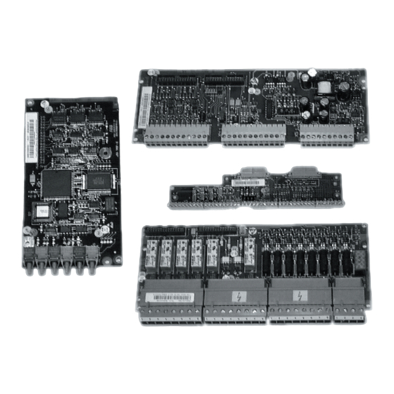
ABB DCS 500B Description (228 pages)
Software for Thyristor Power Converter
Brand:
ABB
| Category:
Media Converter
| Size: 1.46 MB
Table of Contents
Table of Contents
3
General
9
Software Overview
10
Parameter Sets
10
Saving the Program
10
Identification of the Converter Software Version
11
Identification of the Field Exciter Software Version
11
Function Blocks
12
Digital and Analog I/O
13
Digital Inputs
13
Digital Outputs
13
Analog Inputs
14
Analog Outputs
17
Settings and Commissioning Functions
19
SETTINGS Function Block
19
MANUAL TUNING Function Block
20
Autotuning
21
Drive Logic
24
DRIVE LOGIC Function Block
24
Closing Control of the Contactors
24
Opening Control of the Contactors
25
Run Control
25
Stop Control
26
Reset the Drive Fault
28
Change between Parameter Set1 and Set2
29
Local/Remote
29
Speed Feedback and Speed Reference Handling
31
Speed Scaling to Software
31
SPEED_MEASURMENT Function Block
31
Selection of the Speed Actual Measurement
32
Incremental Encoder
32
Analogue Tacho Generator
32
Polarity
32
Scaling of the Actual Voltage to Control
33
Application Example
33
Actual Speed Based on EMF
33
Calculation of Speed from the EMF
33
Filtering of the Actual Speed
33
CONST_REF Function Block
34
SOFTPOT Function Block
34
Reference Increment and Decrement
34
Limitation
34
REF_SEL Function Block
34
Changing of the Speed Direction of Rotation
35
RAMP GENERATOR Function Block
35
Local / Remote Speed Reference
35
Holding of the Reference
35
Ramp Function in Emergency Stop
35
Selecting of the Ramp Function
36
Limitation of the Reference
36
Passing of the RAMP Function
36
Output Follows the Speed Actual
36
Reset the Output
36
Acceleration Compensation
36
Speed Control
38
REFSUM_2 Function Block
38
SPEED_ERROR Function Block
38
Speed Step for Testing
38
Error Value Filter
38
Window Control Principle
39
Application Example for Window Control
39
Enabling the Window Control
39
Determining the Window Size
39
Output Connection Points
39
SPEED_CONTROL Function Block
39
Gain and Integral Time Settings
40
The P-Gain Reduction
40
Output Limitation
40
Integral Part Setting During the Control Mode Changing
41
Principle of Drooping
41
Drooping Adjustment
41
Speed Actual Comparators
42
Overspeed Limit
42
Speed Measurement Fault
42
Stall Protection
42
Torque Reference
45
Torque Reference Scaling
45
Load Sharing in Master / Follower Application
45
Output Limitation
45
TORQUE/CURRENT_LIMITATION Function Block
45
Current Limitations
45
TORQ_REF_SELECTION Function Block
45
Torque Limits
46
Speed Dependant Current Limitation
46
Gear Backlash Compensation
47
Current Control
50
Torque Reference Selection
50
TORQ_REF_HANDLING Function Block
50
Torque Step
51
Output Limitation and Its Indication
51
CURRENT_CONTROL Function Block
51
Torque / Current Reference Selection
51
Current Response Test
51
Regulation Blocking
51
Armature Current Scaling
51
Current Reference Rise Time
51
Current Reference Limitation
51
Current Difference Alarm
51
PI- Regulation
52
Scaling of the Gain KP
52
Scaling of the Time Constant KI
52
Discontinuous Current Point
52
Tuning of Current Regulator
53
Firing Angle Limitation
53
Additional Commutation Reserve DXN
53
Example
53
Network Reactance
54
Short Circuit Current
54
400 A Load
54
Dxn
54
Firing Angle Example
55
Note
55
Status Indication for Bridge
55
Field Excitation
57
Selection of the Field Exciter
58
Field Exciter Status
58
No Field Acknowledge Selected
58
Internal Diode Field Exciter SDCS-FEX-1
58
Internal Field Exciter SDCS-FEX-2
59
Acknowledge
59
External Field Exciter DCF503-0050
59
External Field Exciter DCF504-0050
59
AI/DI Connected Field Exciters
59
Acknowledge Selection
59
Use of the Analog Input Channel
60
Calculation Example
60
Two Field Exciters at the same Time
60
Field Current Settings
60
Free Wheeling Function
61
Trigger Point Setting of the Free Feeling Function
61
Filter for Actual Field Current
61
Field Current Controller
62
Field Reversal
62
Activating
63
Field Direction Change Hysteresis
63
Force Field Direction
63
Field Monitoring When Changing Direction
63
Opti-Torque
64
Selection of OPTI-TORQUE
65
Field Current Reduction Using Torque Reference
65
Field Monitoring When OPTI-TORQUE Changes the Field Direction
66
Field Current / FLUX Linearisation
66
Saturation
67
Linearisation Procedure
67
Field Reduction When at Stand-Still
67
Field Heating When in "OFF"-State
68
The Purpose of EMF Controller
68
Selection of EMF-Control
69
Resistive and Inductive Voltage Drop
69
Field Weakening Area
69
FLUX Reference Handling
70
Flux Reference in Emergency Stop
70
EMF Reference Handling
70
PI - Controller
70
EMF-Error Value Filter
71
PI -Gain Value Scaling
71
PI - Controller Output Limitation
71
Protections
73
Network Voltage Measurement
73
400 V Supply
73
Network Undervoltage
73
Network Overvoltage
73
Overcurrent
73
CONVERTER_PROTECTION Function Block
73
Over -Temperature
74
Earth Fault
74
MOTOR_1_PROTECTION Function Block
75
Alarm and Tripping Limits
76
Motor Protection by Means of the Switch
77
Motor Thermal Model
77
Preloading
79
Thermal Model Selection
79
Alarm and Tripping Limits
79
Thermal Time Constant
80
Brake Control
84
Safety
84
Holding Torque
84
Brake Release
84
Minimum Speed Indication
84
Brake Acknowledge
84
Start Delay
85
Stop Delay
85
Function
85
Tref out
87
Tref Enable
87
Decel Cmnd
87
Lift Brake
87
Brake Run
87
Extended Inputs / Outputs
89
Serial Link Via FIELDBUS
91
• 12 Pulse Configuration
93
DATA LOGGER Function Block
95
User Event
98
Diagnostics
100
FAULT HANDLING Function Block
100
Fault and Alarm Signals
100
Fault Word Bits
100
Alarm Word Bits
100
Fault Logger
100
CONSTANTS Function Block
101
Logical Constants
101
Numerical Constants
101
Dcs 500 Thyristor Power Converters Parameter and Signal List
106
General
108
Parameters of DCS 500
109
Signals of DCS 500
111
Group 1: ANALOG INPUTS
112
Group 2: ANALOG OUTPUTS
116
Group 3: BRAKE CONTROL
118
Group 4: CURRENT CONTROL
119
Group 5: CONVERTER and MOTOR
122
Group 6: DATA LOGGER
127
Group 8: DIGITAL OUTPUTS
129
Group 9: DRIVE LOGIC
131
Group 10: EMF CONTROL
134
Group 11: FAULTS, ALARMS
137
Group 12: MAINTENANCE
140
Group 13: MOTOR 1 FIELD
143
Group 14: MOTOR 1 PROTECT
146
Group 15: MOTOR 2 FIELD
147
Group 16: MOTOR 2 PROTECT
149
Group 17: RAMP GENERATOR
150
Group 18: REFERENCE CHAIN
152
Group 19: REFERENCE SOURCES
153
Group 20: SPEED CONTROLLER
156
Group 21: SPEED MEASUREMENT
158
Group 22: SPEED MONITOR
159
Group 23: TORQUE and CURRENT LIMITS
161
Group 24: TORQUE REFERENCE CHAIN
164
Group 25: FB EXECUTION
165
Group 26: FUNCTION BLOCKS 1
166
Group 27: FUNCTION BLOCKS 2
166
Group 28: FUNCTION BLOCKS 3
166
Group 29: FUNCTION BLOCKS 4
166
Group 30: FUNCTION BLOCKS 5
166
Group 31: FUNCTION BLOCKS 6
166
Group 32: FUNCTION BLOCKS 7
166
Group 34: FUNCTION BLOCKS 9
166
Group 36: 12-PULSE OPERATING
167
Group 37: WINDER PARAMETER
170
Group 38: FUNCTION BLOCKS WINDER
170
Group 39: FUNCTION BLOCKS 10
170
Group 40: FIELDBUS
171
Group 101: ANALOG INPUTS
178
Group 103: BRAKE CONTROL
182
Group 104: CURRENT CONTROL
183
Group 105: CONVERTER, MOTOR
184
Group 106: DATA LOGGER
186
Group 107: DIGITAL INPUTS
187
Group 109: DRIVE LOGIC
190
Group 110: EMF CONTROL
192
Group 111: FAULTS, ALARMS
193
Group 112: MAINTENANCE
197
Group 113: MOTOR 1 FIELD
202
Group 114: MOTOR 1 PROTECT
203
Group 115: MOTOR 2 FIELD
204
Group 116: MOTOR 2 PROTECTION
205
Group 117: RAMP GENERATOR
206
Group 118: REFERENCE CHAIN
207
Group 119: REFERENCE SOURCES
208
Group 120: SPEED CONTROLLER
209
Group 121: SPEED MEASUREMENT
210
Group 122: SPEED MONITOR
211
Group 123: TORQUE and CURRENT LIMITS
212
Group 124: TORQUE REFERENCE CHAIN
213
Group 125: TASKS, CONSTANTS
214
Group 126: FUNCTION BLOCKS 1
217
Group 127: FUNCTION BLOCKS 2
217
Group 128: FUNCTION BLOCKS 3
217
Group 129: FUNCTION BLOCKS 4
217
Group 130: FUNCTION BLOCKS 5
217
Group 135: Ddctool
218
Group 136: 12-PULSE-OPERATING
219
Group 138: FUNCTION WINDER BLOCKS
222
Group 139: FUNCTION BLOCKS 10
222
Advertisement
ABB DCS 500B Service Manual (126 pages)
DCS Thyristor Power Converters for DC Drive Systems 25 to 5200 A
Brand:
ABB
| Category:
Media Converter
| Size: 4.64 MB
Table of Contents
Safety Instructions
5
Table of Contents
9
Chapter 1 - Introduction
13
How to Use this Manual
13
Contents of this Manual
13
Target Group
14
Associated Publications
14
Storage and Transport
14
Rating Plate and Type Code
14
Chapter 2 - Fault Tracing Thyristors
17
How to Detect, if a Thyristor Is Faulty
17
A Fuse Is Blown
17
Ripple Monitor
17
How to Find a Faulty Thyristor
18
Converters Size C1 and C2/C2B (25
18
Blown Fuses
18
Converters Size A5, A6, A7, C3 and C4 (900
19
Blown Fuses
19
Ripple Monitor
19
Chapter 3 - Handling the Semiconductors
21
General Instruction How to Handle the Semiconductors
21
Chapter 4 - Exchange of Thyristors for Sizes C1/C2/C2B
23
Installation of Thyristor Modules in Converters Size C1/C2/C2B (25
23
Required Tools
23
Remove Faulty Thyristor Modules
23
Install New Thyristor Modules
24
Thyristor Module Location
25
Module Terminals
30
Chapter 5 - Exchange of Thyristors for Size A5
33
Installation of "Disc Type" Thyristor in Converters Size A5 (900
33
Required Tools
33
Find Faulty Thyristor
34
Remove Faulty Thyristor
35
Install New Thyristor
36
Chapter 6 - Exchange of Thyristors for Size A6
41
Installation of "Disc Type" Thyristor in Converters Size A6 (1900
41
Required Tools
41
BCT Thyristors
42
Find Faulty Thyristor
43
Remove Faulty Thyristor
44
Install New Thyristor
47
Chapter 7 - Exchange of Thyristors for Size A7
55
Installation of "Disc Type" Thyristor in Converters Size A7 (2050
55
Required Tools
55
Find Faulty Thyristor
56
Chapter 8 - Exchange of Thyristors for Size C3
65
Required Tools
65
Installation of "Disc Type" Thyristor in Converters Size C3 (900...2000 A)
65
Find Faulty Thyristor
66
Remove Faulty Thyristor
66
Install New Thyristor
67
Fasten the Clamp
67
Front View
69
Chapter 9 - Exchange of Thyristors for Size C4
71
Required Tools
71
Find Faulty Thyristor
72
Install New Thyristor
73
Chapter 10 - Service
77
Compatibility of SDCS-PIN-2 Boards
77
Description of SDCS-PIN-20Xb Boards
77
Hardware Coding
77
Snubber Circuit
77
Compatibility of SDCS-PIN-20X Boards
78
Compatibility of SDCS-PIN-20X and SDCS-PIN-2X Boards
78
Change SDCS-PIN-2X Boards
79
Compatibility of Thyristor Modules for Dcsxxx-0200 and Dcsxxx-0250
80
Types Concerned
80
Actual Status
80
Hardware
80
Subject
80
Time Schedule
80
Compatibility
80
DC-Motor Neutral Zone Adjustment
81
Types Concerned
81
Summary
81
General
81
How to Remove the Converter Fan in a Frame A6
82
How to Remove the Converter Fan in a Frame A7
83
SDCS-CON-X Firmware Download Instructions for Windows 2000 and NT 4.0
84
Hardware Configuration
84
Firmware Download Kit
84
Bus Cable
84
Installation
85
Software Configuration
85
PC Operating Systems
85
Drive Software Versions
85
Programs / Files
85
Firmware Download with Windows 2000
86
Recommendation
86
Preparation
88
Hyperterminal Private Edition
91
Flash Erase
91
Flash Program
92
Firmware Download with Windows NT 4.0
94
Recommendation
94
Preparation
94
Hyperterminal
95
Flash Erase
96
Flash Program
96
DCS600 Multidrive - How to Download Firmware on a SDCS-AMC-DC 2 Board under Windows 2000
98
Types Concerned
98
Summary
98
Download DCS600 Multidrive Firmware
98
DCS600 Multidrive - How to Download Firmware on a SDCS-AMC-DC 2 Board under Windows NT 4.0
99
Types Concerned
99
Summary
99
Installation of Ntnisa Drivers
99
Configure PC
100
Types Concerned
101
Summary
101
DCS600 Multidrive - How to Download Parameter Files on a SDCS-AMC-DC X Board
101
Chapter 11 - Preventive Maintainance
103
Recommended Regular Maintenance
103
Air Filters
103
Cooling Air Pressure Switch in Converter Modules Type A6/A7/C4
103
Fan
103
Heatsink
103
Relays and Electrical Connections
104
Internal High Current Connections in Converters Type A7/C4
104
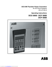
ABB DCS 500B Operating Instructions Manual (76 pages)
DCS 500 Thyristor Power Converters for DC Drive Systems 25 to 5150 A
Brand:
ABB
| Category:
Power Supply
| Size: 1.34 MB
Table of Contents
Operating Instructions
3
Safety Instructions
5
Table of Contents
8
Chapter 1 - Introduction
11
How to Use this Manual
11
Contents of this Manual
11
Target Group
11
Associated Publications
11
Incoming Inspection
12
Storage and Transport
12
Rating Plate
12
Chapter 2 - Start-Up Instructions
13
General Notes
13
Preparatory Work
17
Scaling Intra-Unit Signals
18
Presetting the Field Supply Unit
20
Adjusting the Current Controller
22
Speed Feedback Balancing
24
Balancing the Field Supply Unit and the E.M.f. Controller
26
Balancing the Speed Controller, Plus Fine-Balancing the E.M.f. and the Current Contr
32
Matching the Thyristor Power Converter Unit to the System Conditions Concerned
33
Presetting the 3-Phase Field Supply Unit DCF 50Xb
34
Chapter 3 - Handling of Control Panel CDP 31X
37
Overview
37
Panel Link
37
Mounting the Panel
37
Start Mode
38
Panel Functions
39
Actual Signal Display Mode
39
Parameter Mode
40
Function Mode
40
Drive Mode
41
Pin/Parameter Selecting and Changing of Value
41
Saving of the Parameters to Backup Memory
43
Fault Resetting (Reset)
44
Emergency Stop Resetting (Reset)
44
Fault History Display
45
Uploading and Downloading of Parameters (UPLOAD/DOWNLOAD)
46
Setting of the Display Contrast
48
Full Name of Output Pins
48
Selecting Output Pins
49
Drive Mode
50
Running the Drive
51
Operational Command Keys
51
Running the DC- Drive from the Cdp31X
51
Speed Reference Setting for the Drive
52
Chapter 4 - Signals and Troubleshooting
53
Display of Status, Alarm and Fault Signals
53
Categories of Signals and Possibilities of Display
53
General Messages
54
Starting Errors (E)
54
Fault Signals (F)
55
Alarm Signals (A)
64
Status Signals
69
Connection Diagram 2
74
Advertisement
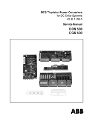
ABB DCS 500B Service Manual (73 pages)
DCS Thyristor Power Converters for DC Drive Systems 25 to 5150 A
Brand:
ABB
| Category:
Media Converter
| Size: 1.57 MB
Table of Contents
Safety Instructions
5
Table of Contents
9
Chapter 1 - Introduction
11
How to Use this Manual
11
Contents of this Manual
11
Target Group
12
Associated Publications
12
Storage and Transport
12
Rating Plate and Type Code
12
Chapter 2 - Fault Tracing Thyristors
15
How to Detect, if a Thyristor Is Faulty
15
A Fuse Is Blown
15
Ripple Monitor
15
How to Find a Faulty Thyristor
16
Converters Size C1 and C2/C2B (25
16
Blown Fuses
16
Converters Size A5, C3 and C4 (900
17
Blown Fuses
17
Ripple Monitor
17
Chapter 3 - Handling the Semiconductors
19
General Instruction How to Handle the Semiconductors
19
Chapter 4 - Exchange of Thyristors for Sizes C1/C2/C2B
21
Installation of Thyristor Modules in Converters Size C1/C2/C2B (25
21
Required Tools
21
Remove Faulty Thyristor Modules
21
Install New Thyristor Modules
22
Install New Thyristor
22
Thyristor Module Location
23
Module Terminals
28
Chapter 5 - Exchange of Thyristors for Size A5
31
Installation of "Disc Type" Thyristor in Converters Size A5 (900
31
Required Tools
31
Find Faulty Thyristor
32
Remove Faulty Thyristor
33
Install New Thyristor
34
Chapter 6 - Exchange of Thyristors for Size C3
39
Installation of "Disc Type" Thyristor in Converters Size C3 (900
39
Required Tools
39
Remove Faulty Thyristor
40
Find Faulty Thyristor
40
Chapter 8 - Compatibility of SDCS-PIN-2 Boards
51
Description of SDCS-PIN-20Xb Boards
51
Hardware Coding
51
Snubber Circuit
51
Compatibility of SDCS-PIN-20X Boards
52
Compatibility of SDCS-PIN-20X and SDCS-PIN-2X Boards
52
Change SDCS-PIN-2X Boards
53
Chapter 9 - Preventive Maintainance
55
Recommended Regular Maintenance
55
Air Filters
55
Cooling Air Pressure Switch in Converter Modules Type C4
55
Fan
55
Heatsink
55
Internal High Current Connections in Converters Type C4
56
Relays and Electrical Connections
56
Advertisement
Related Products
ABB DCF 500B
ABB DCP 500B
ABB DCS550 Series
ABB DCS550-S01
ABB DCS550-S02
ABB DCS 500
ABB DCS880 H8
ABB DCS880 series
ABB DCS800-S01-0090-05
ABB DCS800-EP1-0470-05
ABB Categories
Industrial Equipment
Controller
Measuring Instruments
Battery Charger
DC Drives
More ABB Manuals
Login
Sign In
OR
Sign in with Facebook
Sign in with Google
Upload manual
Upload from disk
Upload from URL