Sign In
Upload
Manuals
Brands
Fujitsu Manuals
Motherboard
MB96300 series
Fujitsu MB96300 series Manuals
Manuals and User Guides for Fujitsu MB96300 series. We have
2
Fujitsu MB96300 series manuals available for free PDF download: Hardware Manual, User Manual
Fujitsu MB96300 series Hardware Manual (1040 pages)
F2MC-16FX 16-bit
Brand:
Fujitsu
| Category:
Microcontrollers
| Size: 8.32 MB
Table of Contents
Table of Contents
9
Overview
15
Features
16
Super Series Lineup
18
Block Diagram of MB96V300
20
General Note on Using this Document
24
16-Bit I/O-Timer Configuration
27
Input Capture Unit Source Select for LIN-USART
31
Peripheral Resource Pin Relocation
38
Cpu
55
Outline of the CPU
56
Hardware Structure
58
Memory Space
62
Special Registers
71
General-Purpose Registers
84
Prefix Codes
88
Interrupts
97
Outline of Interrupts
98
Interrupt Vector
100
Interrupt Control Registers (ICR)
103
Non Maskable Interrupt (NMI)
105
Interrupt Flow
107
Hardware Interrupts
109
Software Interrupts
112
Multiple Interrupts
114
Exceptions
118
Dma
123
Overview
124
DMA Registers
127
DMA Descriptor
133
DMA Controller Operation
141
Examples of DMA Transfers
144
Delayed Interrupt
147
Outline of Delayed Interrupt Module
148
Delayed Interrupt Register
149
Delayed Interrupt Operation
150
Clocks
151
Clocks
152
Clock Control Registers
156
Clock Modes
177
Configuration of the PLL
180
Oscillation Stabilization Wait Time
183
Connection of an Oscillator or an External Clock to the Microcontroller
185
Clock Modulator
187
Overview
188
Register Description
189
Application Note
196
Resets and Startup
199
Resets
200
Reset, System Clock and Stabilization Wait Times
203
Startup after Power and External Reset
205
Boot ROM Program Execution and Operation Mode and ROM Configuration Block
208
Reset Control Registers
216
Operation of the Clock Stop Detection Function and Reset
228
Operation of the Low Voltage Reset Function
232
Standby Mode and Voltage Regulator Control Circuit
235
Overview of the CPU Operating Modes
236
Standby Mode Control Register (SMCR)
242
Voltage Regulator Control Register (VRCR)
245
Standby Modes
248
Mode Change Table and Operation Status
259
Usage Notes on Standby Mode
261
Voltage Regulator Operation
263
Source Clock Timers
269
Overview
270
RC Clock Timer
271
Main Clock Timer
276
Sub Clock Timer
281
Watchdog Timer and Watchdog Reset
287
Outline of Watchdog Timer and Reset
288
Watchdog Timer Control Registers
289
Watchdog Timer Operation
295
External Bus Interface
299
Outline of External Bus
300
External Bus Configuration Registers
306
External Memory Access Control Signal Operation
330
Notes on Using the External Bus
348
External Boot Vector Fetch
352
Pin Status in Different MCU States
354
I/O Ports
357
I/O Ports
358
I/O Port Registers
359
Register Usage
370
16-Bit I/O Timer
371
Outline of 16-Bit I/O Timer
372
16-Bit I/O Timer Registers
374
16-Bit Free-Running Timer
376
Output Compare Unit
383
Input Capture Unit
396
16-Bit Reload Timer (with Event Count Function)
403
Outline of 16-Bit Reload Timer (with Event Count Function)
404
16-Bit Reload Timer (with Event Count Function)
406
Internal Clock and External Event Counter Operations of 16-Bit Reload Timer
411
Underflow Operation of 16-Bit Reload Timer
413
Output Pin Functions of 16-Bit Reload Timer
414
Counter Operation State
415
Cascading of 16-Bit Reload Timers
416
Programmable Pulse Generator
419
Outline of Programmable Pulse Generator
420
Registers
423
Operation of Programmable Pulse Generator
430
Cautions
433
External Interrupts
435
Outline of External Interrupts
436
External Interrupt Registers
438
Notes on Using the External Interrupt Functions
440
A/D Converter
441
Outline of A/D Converter
442
Registers for A/D Converter
444
Operation of A/D Converter
460
Conversion Using DMA
461
Conversion Data Protection Function
462
Alarm Comparator
465
Outline of Alarm Comparator
466
Alarm Comparator Registers
468
Alarm Comparator Operating Modes
471
Usart
473
Overview of USART
474
Configuration of USART
477
USART Pins
482
USART Registers
483
USART Interrupts
504
USART Baud Rates
511
Operation of USART
519
Notes on Using USART
543
400 Khz I2C INTERFACE
549
I2C Interface Overview
550
I2C Interface Registers
552
I2C Interface Operation
575
Programming Flow Charts
578
Can Controller
581
Overview
582
Functional Description
583
Register Description
587
CAN Device Related Registers
592
CAN Protocol Related Registers
594
Message Interface Register Sets
605
Message Object in the Message Memory
615
Message Handler Registers
619
CAN Application
628
Clock Output Function
637
Overview of the Clock Output Function
638
Clock Output Configuration and Activation Registers
639
Operation of the Clock Output Function
645
Real Time Clock
647
Outline of Real Time Clock
648
Real Time Clock Registers
650
Operation
659
Cautions
662
Clock Calibration Unit
665
Outline
666
Register Description
669
Application Notes
673
Lcd Controller/Driver
675
Configuration of LCD Controller/Driver
676
LCD Controller Registers
682
LCD Enable Registers (LCDER, LCDVER)
686
LCD Controller/Driver Display RAM
689
Operation of LCD Controller/Driver
690
Cautions
696
Stepper Motor Controller
699
Outline of Stepper Motor Controller
700
Stepper Motor Controller Registers
701
PWM Control Register (Pwcn)
703
PWM Extended Control Register (Pwecn)
705
PWM1 and PWM2 Compare Registers (Pwc1N, Pwc2N)
706
PWM1 and PWM2 Selection Registers (Pws1N, Pws2N)
709
Operation of Stepper Motor Controller
711
Notes on Using Stepper Motor Controller
714
Sound Generator
715
Outline of Sound Generator
716
Sound Generator Registers
717
Usb Function
727
USB Function Overview
728
USB Function Block Diagram
729
USB Function Registers Description
730
USB Function Operation
761
USB Mini-Host
775
USB Mini-Host Features
776
Differences with USB Host
777
USB Mini-Host Block Diagram
778
USB Mini-Host Registers
779
USB Mini-Host Operation
803
Token Flow Chart
820
Memory Patch Function
823
Outline of the Memory Patch Function
824
Registers of the Memory Patch Function
826
Operation of the Memory Patch Function
837
Rom/Ram Mirroring Module
839
Outline of ROM Mirroring Module
840
ROM Mirroring Register (ROMM)
841
Flash Memory
845
Overview of the Flash Memory
846
Block Diagram of the Flash Memory and Sector Configuration of the Flash Memory
848
Write/Erase Modes
851
Flash Memory Control Registers
852
Starting the Flash Memory Automatic Algorithm
866
Confirming the Automatic Algorithm Execution State
868
Detailed Explanation of Writing to and Erasing Flash Memory
878
Notes on Using Flash Memory
889
Flash Memory Programming Example
890
Mask-Rom Memory Interface
897
Overview
898
ROM Interface Registers
899
Read Buffers
904
Rom/Flash Security
905
Overview of the Rom/Flash Security
906
Usage of the Rom/Flash Security
907
Examples of Serial Programming Connection
911
Basic Configuration of Serial Programming Connection
912
Example of Connecting a PC for Programming the Flash Microcontroller
915
Example of Connecting a Programming Tool for Programming the Flash Microcontroller
916
Advertisement
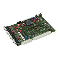
Fujitsu MB96300 series User Manual (36 pages)
MB96300 SERIES
Brand:
Fujitsu
| Category:
Motherboard
| Size: 0.88 MB
Table of Contents
User Guide
1
Revision History
2
Warranty and Disclaimer
3
Table of Contents
4
Contents
4
1 Overview
6
Abstract
6
Features
7
General Description
8
2 Installation
10
Connection/Power-On
10
Default Jumper Settings for MB96370 Series
11
Jumper Location
13
3 Jumpers and Switches
14
Operating Mode (S1)
14
Power Supply (S2, JP: 8, 15, 16, 17, 22)
15
Subclock (JP: 1, 2)
16
Analog Power Supply Voltage (JP: 11, 12, 13, 14)
17
Alarm Comparator (JP: 85)
17
Reset Generation (JP: 33, 41, 46, 47, 48)
18
User Buttons SW1, SW2, SW3, SW4, SW5, SW6 (JP: 3, 4, 5, 6, 7)
19
I 2 C Pull-Up Resistor (JP: 9, 10)
19
Lin / Uart
20
CAN Interfaces (JP: 24, 26, 34, 35)
21
External Flash Memory (JP: 49, 52, 56)
22
External SRAM Memory (JP: 50, 53, 59)
22
Graphic Display Controller Interface (JP: 54, 55, 56, 57, 58, 60, 85, 86)
23
4 Connectors
24
Power Connector (X7)
24
MCU Pin Header Connectors (X20A, X20B, X21, X22 and X23)
24
LIN-UART Connectors (X5, X9)
24
CAN Connector (X6, X8)
25
USER-Leds & Optional LC-Display (J1)
26
In-Circuit-Programming Connector (X4)
27
Alarm Comparator Connector (J2)
28
External Supply Voltage Vin (J3)
28
VCC 5 Volts (J4)
28
VCC 3.3 Volts (J5)
28
VCC 2.5 Volts (J9)
28
VCC 1.8 Volts (J10)
28
LIN Bus Inhibit (J6)
28
LIN Bus Inhibit (J11)
28
VCC Connector (J7)
28
GND Connector (J8)
28
5 Programming the Internal Flash Memory
29
Asynchronous Mode
29
Synchronous Mode
31
6 Appendix
32
Related Products
32
7 Information in the Www
33
8 China-Rohs Regulation
34
9 Recycling
36
Advertisement
Related Products
Fujitsu MB91360 SERIES
Fujitsu MB9B500 Series
Fujitsu MB91470 SERIES
Fujitsu MB95350L Series
Fujitsu MB95390 Series
Fujitsu MB 91F467
Fujitsu MB91V360
Fujitsu MB91FV360
Fujitsu MB90675 Series
Fujitsu MB95F200H
Fujitsu Categories
Air Conditioner
Laptop
Server
Scanner
Storage
More Fujitsu Manuals
Login
Sign In
OR
Sign in with Facebook
Sign in with Google
Upload manual
Upload from disk
Upload from URL