Sign In
Upload
Manuals
Brands
Mitsubishi Electric Manuals
Inverter
FR-F720-04750-NA
Mitsubishi Electric FR-F720-04750-NA Manuals
Manuals and User Guides for Mitsubishi Electric FR-F720-04750-NA. We have
2
Mitsubishi Electric FR-F720-04750-NA manuals available for free PDF download: Instruction Manual, Installation Manuallines
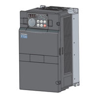
Mitsubishi Electric FR-F720-04750-NA Instruction Manual (347 pages)
F700 Series
Brand:
Mitsubishi Electric
| Category:
Inverter
| Size: 16.08 MB
Table of Contents
Instruction Manual
1
Table of Contents
4
1 Outline
10
Product Checking and Parts Identification
11
Inverter and Peripheral Devices
12
Peripheral Devices
13
Method of Removal and Reinstallation of the
15
Installation of the Inverter and Enclosure Design
17
Inverter Installation Environment
17
Enclosure Design
18
Cooling System Types for Inverter Enclosure
19
Inverter Placement
19
2 Wiring
22
Wiring
23
Terminal Connection Diagram
23
EMC Filter
24
Main Circuit Terminal Specifications
25
Specification of Main Circuit Terminal
25
Terminal Arrangement of the Main Circuit Terminal, Power Supply and the Motor Wiring
25
Cables and Wiring Length
30
When Connecting the Control Circuit and the Main Circuit Separately to the Power Supply
34
Control Circuit Specifications
36
Control Circuit Terminals
36
Changing the Control Logic
39
Control Circuit Terminal Layout
41
Wiring Instructions
42
When Connecting the Operation Panel Using a Connection Cable
43
Terminal Block
44
Communication Operation
44
Connection of Stand-Alone Option Units
45
Connection of the Brake Unit (FR-BU2)
45
Connection of the Brake Unit (FR-BU/MT-BU5)
47
Connection of the Brake Unit (BU Type)
49
Connection of the High Power Factor Converter (FR-HC/MT-HC)
49
Connection of the Power Regeneration Common Converter (FR-CV)(FR-F720-02330 (FR-F740- 01160) or Less)
51
Connection of the Power Regeneration Converter (MT-RC) (FR-F720-03160 (FR-F740-01800) or More)
52
Connection of the Power Factor Improving DC Reactor (FR-HEL)
52
3 Precautions for Use of the Inverter
54
EMC and Leakage Currents
55
Leakage Currents and Countermeasures
55
EMC Measures
57
Power Supply Harmonics
59
Installation of a Reactor
60
Power-Off and Magnetic Contactor (MC)
60
Inverter-Driven 400V Class Motor
61
Precautions for Use of the Inverter
62
Failsafe of the System Which Uses the Inverter
64
4 Parameters
66
Operation Panel (FR-DU07)
67
Parts of the Operation Panel (FR-DU07)
67
Basic Operation (Factory Setting)
68
Changing the Parameter Setting Value
69
Setting Dial Push
69
Parameter List
70
Adjustment of the Output Torque (Current) of the Motor
82
Manual Torque Boost (Pr. 0, Pr. 46)
82
Simple Magnetic Flux Vector Control (Pr.80, Pr.90)
83
Slip Compensation (Pr. 245 to Pr. 247)
84
Stall Prevention Operation (Pr. 22, Pr. 23, Pr. 48, Pr. 49, Pr. 66, Pr. 148, Pr. 149, Pr. 154, Pr. 156, Pr. 157)
85
Stall Prevention Operation
85
Multiple Rating (Pr.570)
90
Limiting the Output Frequency
91
Maximum/Minimum Frequency (Pr. 1, Pr. 2, Pr. 18)
91
Avoiding Mechanical Resonance Points (Frequency Jump) (Pr. 31 to Pr. 36)
92
V/F Pattern
93
Base Frequency, Voltage (Pr. 3, Pr. 19, Pr. 47)
93
Load Pattern Selection (Pr. 14)
95
Adjustable 5 Points V/F (Pr. 71, Pr. 100 to Pr. 109)
96
Frequency Setting by External Terminals
97
Multi-Speed Setting Operation (Pr. 4 to Pr. 6, Pr. 24 to Pr. 27, Pr. 232 to Pr. 239)
97
Jog Operation (Pr. 15, Pr. 16)
99
Input Compensation of Multi-Speed and Remote Setting (Pr. 28)
101
Remote Setting Function (Pr. 59)
102
Setting of Acceleration/Deceleration Time and Acceleration/Deceleration Pattern
105
Setting of the Acceleration and Deceleration Time (Pr.7, Pr.8, Pr.20, Pr.21, Pr.44, Pr.45)
105
Starting Frequency and Start-Time Hold Function (Pr.13, Pr.571)
107
Acceleration/Deceleration Pattern (Pr.29, Pr.140 to Pr.143)
108
Selection and Protection of a Motor
110
Motor Protection from Overheat (Electronic Thermal Relay Function) (Pr. 9, Pr. 51)
110
Applied Motor (Pr. 71)
114
Motor Brake and Stop Operation
115
DC Injection Brake (Pr. 10 to Pr. 12)
115
Selection of a Regenerative Brake and DC Feeding (Pr. 30, Pr. 70)
117
Stop Selection (Pr. 250)
122
Output Stop Function (Pr.522)
123
Function Assignment of External Terminal and Control
125
Input Terminal Function Selection (Pr. 178 to Pr. 189)
125
Inverter Output Shutoff Signal (MRS Signal, Pr. 17)
127
Condition Selection of Function Validity by the Second Function Selection Signal (RT) (RT Signal, Pr. 155)
128
Start Signal Selection (STF, STR, STOP Signal, Pr. 250)
129
Output Terminal Function Selection (Pr. 190 to Pr. 196)
131
Detection of Output Frequency (SU, FU, FU2 Signal, Pr. 41 to Pr. 43, Pr. 50)
135
Output Current Detection Function (Y12 Signal, Y13 Signal, Pr. 150 to Pr. 153, Pr. 166, Pr. 167)
136
Output Current Detection Function
136
Remote Output Function (REM Signal, Pr. 495 to Pr. 497)
138
Pulse Train Output of Output Power (Y79 Signal, Pr. 799)
139
Monitor Display and Monitor Output Signal
140
Speed Display and Speed Setting (Pr. 37, Pr. 144)
140
DU/PU Monitor Display Selection (Pr. 52, Pr. 54, Pr. 158, Pr. 170, Pr. 171, Pr. 268, Pr. 563, Pr. 564, Pr. 891)
141
DU/PU Monitor Display Selection
141
CA, am Terminal Function Selection (Pr.55, Pr.56, Pr.867, Pr.869)
146
Terminal CA, am Calibration (Calibration Parameter C0 (Pr. 900), C1 (Pr. 901), C8 (Pr.930) to C11 (Pr. 931))
148
Operation Selection at Power Failure and Instantaneous Power Failure
151
Automatic Restart after Instantaneous Power Failure / Flying Start (Pr. 57, Pr. 58, Pr. 162 to Pr. 165, Pr. 299, Pr. 611)
151
Instantaneous Power Failure
153
Power Failure-Time Deceleration-To-Stop Function (Pr. 261 to Pr. 266 )
155
Operation Setting at Fault Occurrence
158
Retry Function (Pr. 65, Pr. 67 to Pr. 69)
158
Fault Code Output Selection (Pr.76)
160
Input/Output Phase Loss Protection Selection (Pr. 251, Pr. 872)
161
Energy Saving Operation and Energy Saving Monitor
162
Energy Saving Control and Optimum Excitation Control (Pr. 60)
162
Energy Saving Monitor (Pr. 891 to Pr. 899)
163
Motor Noise, EMI Measures, Mechanical Resonance
168
PWM Carrier Frequency and Soft-PWM Control (Pr. 72, Pr. 240, Pr. 260)
168
Speed Smoothing Control (Pr. 653, Pr. 654)
169
Frequency Setting by Analog Input (Terminal 1, 2, 4)
170
Analog Input Selection (Pr. 73, Pr. 267)
170
Analog Input Compensation (Pr. 73, Pr. 242, Pr. 243, Pr. 252, Pr. 253)
175
Response Level of Analog Input and Noise Elimination (Pr. 74)
176
Bias and Gain of Frequency Setting Voltage (Current) (Pr. 125, Pr. 126, Pr. 241, C2(Pr. 902) to C7(Pr. 905))
177
4Ma Input Check of Current Input (Pr. 573)
182
Misoperation Prevention and Parameter Setting Restriction
184
Reset Selection/Disconnected PU Detection/Pu Stop Selection (Pr. 75)
184
Parameter Write Selection (Pr. 77)
187
Reverse Rotation Prevention Selection (Pr. 78)
188
Display of Applied Parameters and User Group Function (Pr. 160, Pr. 172 to Pr. 174)
188
Selection of Operation Mode and Operation Location
190
Operation Mode Selection (Pr. 79)
190
Operation Mode at Power on (Pr. 79, Pr. 340)
198
Start Command Source and Speed Command Source During Communication Operation (Pr. 338, Pr. 339, Pr. 550, Pr. 551)
199
Communication Operation and Setting
204
Wiring and Configuration of PU Connector
204
System Configuration
205
Wiring and Arrangement of RS-485 Terminals
206
Initial Settings and Specifications of RS-485 Communication (Pr. 117 to Pr. 124, Pr. 331 to Pr. 337, Pr. 341, Pr. 549)
209
Communication EEPROM Write Selection (Pr. 342)
210
Mitsubishi Inverter Protocol (Computer Link Communication)
211
Run Command
221
Modbus-RTU Communication Specifications (Pr. 331, Pr. 332, Pr. 334, Pr. 343, Pr. 539, Pr. 549)
222
Special Operation and Frequency Control
234
PID Control (Pr. 127 to Pr. 134, Pr. 241, Pr. 553, Pr. 554, Pr. 575 to Pr. 577, C42 (Pr. 934) to C45 (Pr. 935))
234
Special Operation and Frequency Control
235
Bypass-Inverter Switchover Function (Pr. 135 to Pr. 139, Pr. 159)
246
Advanced PID Function (Pump Function) (Pr. 554, Pr. 575 to Pr. 591)
251
Regeneration Avoidance Function (Pr. 882 to Pr. 886)
261
Useful Functions
263
Cooling Fan Operation Selection (Pr. 244)
263
Display of the Life of the Inverter Parts (Pr. 255 to Pr .259)
264
Maintenance Timer Alarm (Pr. 503, Pr. 504)
267
Current Average Value Monitor Signal (Pr. 555 to Pr. 557)
268
Free Parameter (Pr. 888, Pr. 889)
270
Setting from the Parameter Unit, Operation Panel
271
PU Display Language Selection (Pr. 145)
271
Operation Panel Frequency Setting/Key Lock Selection (Pr. 161)
271
Buzzer Control (Pr. 990)
273
PU Contrast Adjustment (Pr. 991)
273
Parameter Clear
274
All Parameter Clear
275
Parameter Copy and Parameter Verification
276
Parameter Copy
276
Parameter Verification
277
Check and Clear of the Faults History
278
5 Protective Functions
280
Reset Method of Protective Function
281
List of Fault or Alarm Display
282
Causes and Corrective Actions
283
Correspondences between Digital and Actual Characters
294
Check First When You Have a Trouble
295
Motor Does Not Start
295
Motor or Machine Is Making Abnormal Acoustic Noise
297
Inverter Generates Abnormal Noise
297
Motor Generates Heat Abnormally
297
Motor Rotates in the Opposite Direction
298
Speed Greatly Differs from the Setting
298
Acceleration/Deceleration Is Not Smooth
298
Speed Varies During Operation
299
Operation Mode Is Not Changed Properly
299
Operation Panel (FR-DU07) Display Is Not Operating
300
Motor Current Is too Large
300
Speed Does Not Accelerate
301
Unable to Write Parameter Setting
301
Power Lamp Is Not Lit
301
6 Precautions for Maintenance and Inspection
302
Inspection Item
303
Daily Inspection
303
Periodic Inspection
303
Daily and Periodic Inspection
304
Display of the Life of the Inverter Parts
305
Checking the Inverter and Converter Modules
305
Cleaning
306
Replacement of Parts
306
Inverter Replacement
310
Measurement of Main Circuit Voltages, Currents and Powers
311
Measurement of Voltages and Currents
311
Measurement of Powers
313
Measurement of Voltages and Use of PT
313
Measurement of Currents
314
Use of CT and Transducer
314
Measurement of Inverter Input Power Factor
314
Measurement of Converter Output Voltage (Across Terminals P/+ - N/-)
315
Insulation Resistance Test Using Megger
315
Pressure Test
315
7 Specifications
316
Rating
317
Common Specifications
319
Outline Dimension Drawings
321
Inverter Outline Dimension Drawings
321
Heatsink Protrusion Attachment Procedure
331
When Using a Heatsink Protrusion Attachment (FR-A7CN)
331
Protrusion of Heatsink of the FR-F740-04320 or more
331
Appendices
334
Appendix 1 for Customers Who Are Replacing the Conventional Model with this Inverter
335
Appendix 1-1 Replacement of the FR-F500 Series
335
Appendix 1-2 Replacement of the FR-A100 <EXCELENT> Series
336
Instructions for Installation
336
Appendix 2 Parameter Clear, Parameter Copy and Instruction Code List
337
Appendix 3 Specification Change
345
Appendix 3-1 SERIAL Number Check
345
Appendix 3-2 Changed Functions
345
Advertisement
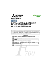
Mitsubishi Electric FR-F720-04750-NA Installation Manuallines (28 pages)
F700 Series
Brand:
Mitsubishi Electric
| Category:
Inverter
| Size: 2.18 MB
Table of Contents
Table of Contents
1
Installation of the Inverter and Instructions
4
Outline Drawing
5
Wiring
7
Control Circuit Terminals
13
Precautions for Use of the Inverter
14
Failsafe of the System Which Uses the Inverter
15
Parameter List
16
Troubleshooting
22
List of Fault or Alarm Display
23
Initial
25
Advertisement
Related Products
Mitsubishi Electric FR-F720-0.75K to 110K
Mitsubishi Electric FR-F720-00046
Mitsubishi Electric FR-F720-00046-NA
Mitsubishi Electric FR-F720-00077-NA
Mitsubishi Electric FR-F720-00105-NA
Mitsubishi Electric FR-F720-00167-NA
Mitsubishi Electric FR-F720-00250-NA
Mitsubishi Electric FR-F720-00340-NA
Mitsubishi Electric FR-F720-00490-NA
Mitsubishi Electric FR-F720-00630-NA
Mitsubishi Electric Categories
Air Conditioner
Controller
Projector
Inverter
Heat Pump
More Mitsubishi Electric Manuals
Login
Sign In
OR
Sign in with Facebook
Sign in with Google
Upload manual
Upload from disk
Upload from URL