Sign In
Upload
Manuals
Brands
Motorola Manuals
Radio
ASTRO XTL 2500
Motorola ASTRO XTL 2500 Manuals
Manuals and User Guides for Motorola ASTRO XTL 2500. We have
4
Motorola ASTRO XTL 2500 manuals available for free PDF download: User Manual, Installation Manual
Motorola ASTRO XTL 2500 User Manual (164 pages)
Digital Mobile Radio Control Head
Brand:
Motorola
| Category:
Radio
| Size: 0.94 MB
Table of Contents
Declaration of Conformity
5
Computer Software Copyrights
6
Documentation Copyrights
6
Disclaimer
6
Notations Used in this Manual
7
Table of Contents
9
Introduction
15
Using Your Radio: the Basics
15
Getting Started
16
Identifying Your Radio
18
Control Head
18
Operating Your Control Head
19
Turning on the Radio
19
Setting the Volume
20
Adjusting the Display Brightness
20
Using the Navigation Keys
20
Keypad Microphone Option
21
Trunked Modes or Conventional Channels
22
Field Programming
22
Display Status
22
Feature Control
23
Menu
23
Programmable Buttons
23
One Touch Button
23
Alert Tones
24
Multiple Control Head Features
27
Overview
27
Setting the Initial Control Head's ID
29
All Active Mode
30
One Active Mode
31
Intercom Feature
33
Using the Intercom Feature
33
Basic Operating Procedures
37
Basic Functions
37
Selecting the Zone or Mode
38
Selecting or Changing the Zone
38
Selecting or Changing a Mode in the Current Zone
39
Selecting or Changing to a Mode Not in the Current Zone
40
Mode Select Button
41
Selecting the Home Mode
42
Transmitting (Conventional Modes Only)
42
Transmitting (Trunked Modes Only)
43
Selecting the Transmit Power Level
43
Monitoring Conventional Mode Activity
44
Adjusting the Squelch Level
45
General Radio Features
46
Often-Used Features
46
Emergency Call and Alarm
47
Emergency Call
47
Initiating an Emergency Alarm
48
Initiating an Emergency Call
48
Initiating an Emergency Call and Alarm
49
Initiating a Silent Emergency Alarm
50
Special Considerations for Emergencies
50
Scan Operation
51
Turning on Scan
52
Turning Scan on While Disregarding the Squelch Code (Conventional Modes Only)
53
Viewing a Scan List
54
Transmitting While Scan Is on
55
Temporarily Deleting a Nuisance Mode with Scan on
56
Restoring a Nuisance Mode
56
Changing Mode Priorities While Scan Is on
57
Restoring Mode Priorities in a Scan List
57
Programming a Scan List
58
Hang up Box (HUB)
60
Optional External Alarms (Horn and Lights)
60
Activating the External Alarm(S)
60
Changing the Selected Alarms
61
Receiving a Call While Alarms Are Turned on
62
Time-Out Timer
63
Push-To-Talk Identification (PTT-ID)
63
Telephone Interconnect List (Conventional and Trunking)
64
Answering a Phone Call
64
Initiating a Telephone Call from the List
65
Unlimited Telephone Interconnect
66
Calling a Phone Number Not in the List
66
Storing a Number in the List
67
Editing a Name in the List
68
Call Alert Page (Conventional and Trunking-Digital Modes Only)
71
Sending a Call Alert Page
71
Conventional Radio Features
73
Features Used in Conventional Operation
73
Status Calls (Digital Modes Only)
74
Sending a Status Call
74
Sending a Direct-Entry Keyboard (DEK) Status
76
Smart PTT
77
Conventional Talkgroup Calls
77
Digital Modes Only
77
Selecting a Conventional Talkgroup
78
Conventional Talkaround
79
Talk Direct (Mobile-To-Mobile)
79
Selective Calls (Digital Modes Only)
79
Answering a Selective Call
80
Initiating a Selective Call
81
Viewing Your Unit ID Number
83
Storing a Unit ID Number in the List
84
Editing a Name in the List
85
Trunking Operation
87
Features Used on Trunking Systems
87
Enhanced Private Conversation (Digital Modes Only)
88
Answering an Enhanced Private Conversation Call
88
Initiating an Enhanced Private Conversation Call
89
Failsoft
91
Dynamic Regrouping (Digital Modes Only)
92
Receiving a Dynamic Regrouping ID Assignment
92
Selecting Enable and Disable (Digital Modes Only)
93
Requesting a Dynamic Regrouping (Digital Modes Only)
93
Smartzone
94
Site-Button Operation
94
Locking Onto a Site
95
Site Trunking
95
Out-Of-Range Indication
96
Trunked Announcement
97
Initiating an Announcement
97
ARS User Login and Text Messaging Features
99
Automatic Registration Service (ARS)
99
Selecting or Changing ARS Mode
99
ARS User Login Feature
101
Accessing the User Login Feature
101
To Login as a User
102
Selecting a Predefined Username
107
Text Messaging
108
Accessing TMS Feature
108
Receive a Message
113
To View Message from the Inbox
113
Compose a New Text Message
114
Send a Predefined Message
118
Edit a Quick Text Message
119
Reply to a Received Message
120
Delete a Message
121
To Access the Draft Folder
122
To Access the Sent Folder
123
Secure Operation
125
Features Available on Secure XTL 2500
125
Receiving a Private Message
126
Transmitting a Private Message
126
System Considerations
127
Loss Indication
127
Selecting an Encryption Key (Conventional Only)
128
Selecting an Encryption Index (Conventional Only)
130
Troubleshooting
131
Accessories
133
Antennas
133
Bull Horns for Siren and Public Address
135
Cables
135
Microphones
136
Miscellaneous
136
Remote Mounting Kits
137
Speakers
137
Trunnion Kits
137
Appendix: Maritime Radio Use in the VHF Frequency Range
138
Special Channel Assignments
138
Emergency Channel
138
Non-Commercial Call Channel
139
Operating Frequency Requirements
139
Glossary
143
Commercial Warranty and Service
147
Limited Warranty
147
Service
151
Index
153
Advertisement
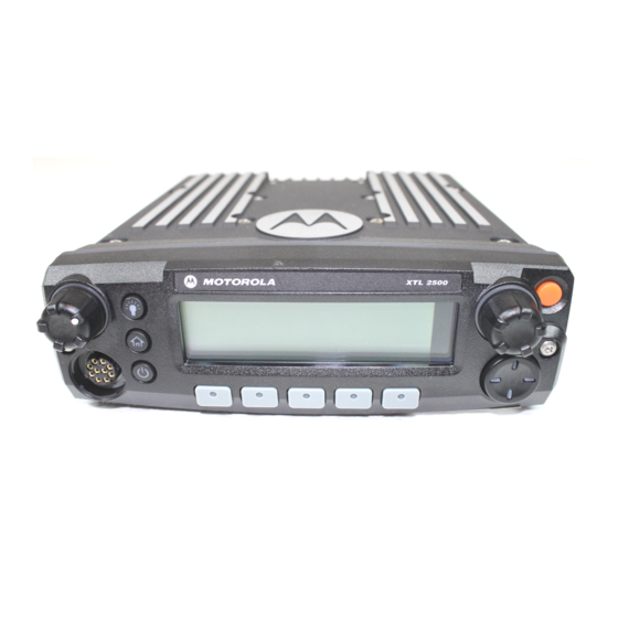
Motorola ASTRO XTL 2500 User Manual (161 pages)
Digital Mobile Radio with M5 Control Head
Brand:
Motorola
| Category:
Radio
| Size: 3.51 MB
Table of Contents
M5 Control Head
3
Declaration of Conformity
5
Computer Software Copyrights
6
Documentation Copyrights
6
Disclaimer
6
Notations Used in this Manual
7
Table of Contents
9
Introduction
15
Using Your Radio: the Basics
15
Getting Started
16
Identifying Your Radio
18
M5 Control Head
18
Operating Your Control Head
19
Turning on the Radio
19
Setting the Volume
20
Adjusting the Display Brightness
20
Using the Navigation Keys
20
Keypad Microphone Option
21
Trunked Modes or Conventional Channels
22
Field Programming
22
Display Status
22
Feature Control
23
Menu
23
Programmable Buttons
23
One Touch Button
23
Alert Tones
24
Multiple Control Head Features
27
Overview
27
All Active Mode
28
One Active Mode
29
Intercom Feature
31
Using the Intercom Feature
31
Basic Operating Procedures
35
Basic Functions
35
Selecting the Zone or Mode
36
Selecting or Changing the Zone
36
Selecting or Changing a Mode in the Current Zone
37
Selecting or Changing to a Mode Not in the Current Zone
38
Mode Select Button
39
Selecting the Home Mode
40
Transmitting (Conventional Modes Only)
40
Transmitting (Trunked Modes Only)
41
Selecting the Transmit Power Level
41
Monitoring Conventional Mode Activity
42
Adjusting the Squelch Level
43
General Radio Features
44
Often-Used Features
44
Emergency Call and Alarm
45
Emergency Call
45
Initiating an Emergency Alarm
46
Initiating an Emergency Call
46
Initiating an Emergency Call and Alarm
47
Initiating a Silent Emergency Alarm
48
Special Considerations for Emergencies
48
Scan Operation
49
Turning on Scan
50
Turning Scan on While Disregarding the Squelch Code (Conventional Modes Only)
51
Viewing a Scan List
52
Transmitting While Scan Is on
53
Temporarily Deleting a Nuisance Mode with Scan on
54
Restoring a Nuisance Mode
54
Changing Mode Priorities While Scan Is on
55
Restoring Mode Priorities in a Scan List
55
Programming a Scan List
56
Hang up Box (HUB)
58
Optional External Alarms (Horn and Lights)
58
Activating the External Alarm(S)
58
Changing the Selected Alarms
59
Receiving a Call While Alarms Are Turned on
60
Time-Out Timer
61
Push-To-Talk Identification (PTT-ID)
61
Telephone Interconnect List (Conventional and Trunking)
62
Answering a Phone Call
62
Initiating a Telephone Call from the List
63
Unlimited Telephone Interconnect
64
Calling a Phone Number Not in the List
64
Storing a Number in the List
65
Editing a Name in the List
66
Call Alert Page (Conventional and Trunking-Digital Modes Only)
69
Sending a Call Alert Page
69
Conventional Radio Features
71
Features Used in Conventional Operation
71
Status Calls (Digital Modes Only)
72
Sending a Status Call
72
Sending a Direct-Entry Keyboard (DEK) Status
74
Smart PTT
75
Conventional Talkgroup Calls
75
Digital Modes Only
75
Selecting a Conventional Talkgroup
76
Conventional Talkaround
77
Talk Direct (Mobile-To-Mobile)
77
Selective Calls (Digital Modes Only)
77
Answering a Selective Call
78
Initiating a Selective Call
79
Viewing Your Unit ID Number
81
Storing a Unit ID Number in the List
82
Editing a Name in the List
83
Trunking Operation
85
Features Used on Trunking Systems
85
Enhanced Private Conversation (Digital Modes Only)
86
Answering an Enhanced Private Conversation Call
86
Initiating an Enhanced Private Conversation Call
87
Failsoft
89
Dynamic Regrouping (Digital Modes Only)
90
Receiving a Dynamic Regrouping ID Assignment
90
Selecting Enable and Disable (Digital Modes Only)
91
Requesting a Dynamic Regrouping (Digital Modes Only)
91
Smartzone
92
Site-Button Operation
92
Locking Onto a Site
93
Site Trunking
93
Out-Of-Range Indication
94
ASTRO XTL 2500 Digital Mobile Radio with M5 Control Head
95
Trunked Announcement
95
Initiating an Announcement
95
ARS User Login and Text Messaging Features
97
Automatic Registration Service (ARS)
97
Selecting or Changing ARS Mode
97
ARS User Login Feature
99
Accessing the User Login Feature
99
To Login as a User
100
Selecting a Predefined Username
105
Text Messaging
106
Accessing TMS Feature
106
Receive a Message
111
To View Message from the Inbox
111
Compose a New Text Message
112
Send a Predefined Message
116
Edit a Quick Text Message
117
Reply to a Received Message
118
Delete a Message
119
To Access the Draft Folder
120
To Access the Sent Folder
121
Secure Operation
123
Features Available on Secure XTL 2500
123
Receiving a Private Message
124
Transmitting a Private Message
124
System Considerations
125
Loss Indication
125
Selecting an Encryption Key (Conventional Only)
126
Selecting an Encryption Index (Conventional Only)
128
Troubleshooting
129
Accessories
131
Antennas
131
Bull Horns for Siren and Public Address
133
Cables
133
Microphones
134
Miscellaneous
134
Remote Mounting Kits
135
Speakers
135
Trunnion Kits
135
Appendix: Maritime Radio Use in the VHF Frequency Range
136
Special Channel Assignments
136
Emergency Channel
136
Non-Commercial Call Channel
137
Operating Frequency Requirements
137
Glossary
141
Commercial Warranty and Service
145
Limited Warranty
145
Service
149
Index
151
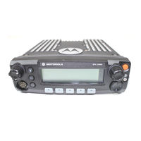
Motorola ASTRO XTL 2500 User Manual (120 pages)
Digital Mobile Radio O5 Control Head
Brand:
Motorola
| Category:
Radio
| Size: 0.34 MB
Table of Contents
Declaration of Conformity
3
Computer Software Copyrights
4
Documentation Copyrights
4
Disclaimer
4
Notations Used in this Manual
5
Table of Contents
7
Introduction
11
Using Your Radio: the Basics
11
Getting Started
12
Identifying Your Radio
14
O5 Control Head
14
Operating Your Control Head
14
Turning on the Radio
15
Setting the Volume
16
Adjusting the Display Brightness
16
Using the Navigation Key
16
Trunked Modes or Conventional Channels
17
Field Programming
17
Display Status
18
Feature Control
18
Alert Tones
18
Basic Operating Procedures
21
Basic Functions
21
Selecting the Zone or Mode
22
Selecting or Changing the Zone
22
Selecting or Changing a Mode in the Current Zone
23
Selecting or Changing to a Mode Not in the Current Zone
23
Selecting the Home Mode
24
Transmitting (Conventional Modes Only)
25
Transmitting (Trunked Modes Only)
25
Selecting the Transmit Power Level
26
Monitoring Conventional Mode Activity
26
Adjusting the Squelch Level
27
General Radio Features
28
Often-Used Features
28
Emergency Call and Alarm
29
Emergency Call
29
Initiating an Emergency Alarm
30
Initiating an Emergency Call
30
Initiating an Emergency Call and Alarm
31
Initiating a Silent Emergency Alarm
32
Special Considerations for Emergencies
32
Scan Operation
33
Turning on Scan
34
Turning Scan on While Disregarding the Squelch Code (Conventional Modes Only)
35
Viewing a Scan List
36
Transmitting While Scan Is on
37
Temporarily Deleting a Nuisance Mode with Scan on
38
Restoring a Nuisance Mode
38
Changing Mode Priorities While Scan Is on
39
Restoring Mode Priorities in a Scan List
39
Programming a Scan List
40
Hang up Box (HUB)
42
Optional External Alarms (Horn and Lights)
42
Activating the External Alarm(S)
42
Changing the Selected Alarms
43
Receiving a Call While Alarms Are Turned on
44
Time-Out Timer
45
Push-To-Talk Identification (PTT-ID)
45
Telephone Interconnect List (Conventional and Trunking)
46
Answering a Phone Call
46
Initiating a Telephone Call from the List
47
Unlimited Telephone Interconnect
48
Calling a Phone Number Not in the List
48
Storing a Number in the List
49
Editing a Name in the List
50
Call Alert Page (Conventional and Trunking-Digital Modes Only)
53
Sending a Call Alert Page
54
Conventional Radio Features
57
Features Used in Conventional Operation
57
Status Calls (Digital Modes Only)
58
Sending a Status Call
58
Smart PTT
60
Conventional Talkgroup Calls
60
Digital Modes Only
60
Selecting a Conventional Talkgroup
61
Conventional Talkaround
62
Talk Direct (Mobile-To-Mobile)
62
Selective Calls (Digital Modes Only)
62
Answering a Selective Call
63
Initiating a Selective Call
64
Viewing Your Unit ID Number
66
Storing a Unit ID Number in the List
67
Editing a Name in the List
68
Trunking Operation
71
Features Used on Trunking Systems
71
Enhanced Private Conversation (Digital Modes Only)
72
Answering an Enhanced Private Conversation Call
72
Initiating an Enhanced Private Conversation Call
73
Failsoft
75
Dynamic Regrouping (Digital Modes Only)
76
Receiving a Dynamic Regrouping ID Assignment
76
Selecting Enable and Disable (Digital Modes Only)
77
Requesting a Dynamic Regrouping (Digital Modes Only)
77
Smartzone
78
Site-Button Operation
78
Locking Onto a Site
79
Site Trunking
79
Out-Of-Range Indication
80
Trunked Announcement
81
Initiating an Announcement
81
Secure Operation
83
Features Available on Secure XTL 5000
83
Receiving a Private Message
84
Transmitting a Private Message
84
System Considerations
85
Loss Indication
85
Selecting an Encryption Key (Conventional Only)
86
Selecting an Encryption Index (Conventional Only)
88
Troubleshooting
89
Accessories
91
Antennas
91
Bull Horns for Siren and Public Address
93
Cables
93
Microphones
94
Miscellaneous
94
Remote Mounting Kits
95
Speakers
95
Trunnion Kits
95
Appendix: Maritime Radio Use in the VHF Frequency Range
96
Special Channel Assignments
96
Emergency Channel
96
Non-Commercial Call Channel
97
Operating Frequency Requirements
97
Glossary
101
Limited Warranty
103
Commercial Warranty and Service
105
Service
107
Index
111
Advertisement
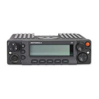
Motorola ASTRO XTL 2500 Installation Manual (73 pages)
Digital Mobile Radio M5 Control Head
Brand:
Motorola
| Category:
Radio
| Size: 3.75 MB
Table of Contents
Foreword
2
Parts Ordering
2
Computer Software Copyrights
2
Document Copyrights
2
Disclaimer
2
Trademarks
2
Installation Requirements for Compliance with Radio Frequency (RF) Energy Exposure Safety Standards
3
Table of Contents
5
Mobile Radio Model Numbering Scheme
10
Commercial Warranty
12
Limited Warranty
12
Motorola Communication Products
12
What this Warranty Covers and for How Long
12
II. General Provisions
12
III. State Law Rights
13
IV. How to Get Warranty Service
13
What this Warranty Does Not Cover
13
VI. Patent and Software Provisions
14
VII. Governing Law
14
Chapter 1 Introduction
16
Mobile Radio Description
16
Dimensions
16
Dash Mount Configuration
17
Remote Mount Configuration
17
Figure 1-3. Dash Mount Configuration
17
Figure 1-4. Remote Mount Configuration
17
Base/Control Stations
18
Figure 1-5. Remote Mount Configuration, with 110W Transceiver
18
Tools Required for XTL 2500 Installations
19
Chapter 2 Standard Configurations
20
Planning the Installation
20
Figure 2-1. Mounting Flexibility in Middle Console (Cannot be Used for 110W Radios)
21
Figure 2-2. on Top or under Dash Mounting (Cannot be Used for 110W Radios)
21
Figure 2-3. Remote Mount-Control Head in Console
21
Figure 2-4. in Dash Mounting (Cannot be Used for 110W Radios)
21
Figure 2-5. Remote Mount-Control Head in Dash
21
Figure 2-6. Remote Mount-Control Head on Top or under Dash
21
Figure 2-7. Radio Installation (Dash Mount) with Transceiver
22
Wiring Diagrams
22
Figure 2-8. Radio Installation (Remote Midpower with Pinouts)
23
Figure 2-9. Radio Installation (110W Remote Highpower with Pinouts)
23
Radio Mounting
24
Figure 2-10. Trunnion Orientation (Cannot be Used for 110W Radios)
24
Figure 2-11. Trunnion Orientation for 110W Radios(Quick Release Trunnion)
25
Figure 2-12. Trunnion Orientation for 110W Radios(Screw-Mounted Trunnion)
25
Figure 2-13. Transmission Hump Trunnion Mounting
26
Remote Mount with Trunnion
27
2.2.2.1 Transceiver
27
Figure 2-14. below Dash Trunnion Mounting
27
Figure 2-15. 110W Radio Mounting into Quick Release Trunnion
28
Figure 2-16. 110W Radio Mounting into Screw-Mounted Trunnion
29
2.2.2.2 Control Head and Remote Mount Cabling
30
Figure 2-17. M5 Control Head
30
Figure 2-18. Control Head Installation Exploded View
31
Figure 2-19. Control Head Rear View
31
Table 2-1. Radio Functions Connections
32
Figure 2-20. Fuseholder Assembly for Yellow and Red Control Cables
33
Locking Kit (Optional)
34
2.2.3.1 All Radios Except 110W
34
Figure 2-21. Locking Kit (Optional) (Cannot be Used for 110W Radios)
34
Table 2-2. Fuse Assembly for Yellow and Red Leads Parts List
34
Power Cable
35
Figure 2-22. Lock Supplied with 110W Quick Release Trunnion
35
W Radios
35
Ignition Sense Cable
38
Antenna Installation
38
Selecting an Antenna Site/Location on a Metal Body Vehicle
38
Mini-UHF Connection
39
Figure 2-25. Mini-UHF Connection (as Shown on MID-Power)
39
Figure 2-26. Mini-UHF Connection (110W Radios Only)
39
Figure 2-27. Mini-UHF Connector Tool (as Shown on MID-Power)
40
Figure 2-28. Mini-UHF Connector Tool (110W Radios Only)
40
Speaker
41
Figure 2-29. Speaker Mounting
41
Microphone Hang-Up Clip
42
Standard Hang-Up Clip
42
Handheld Hang-Up Box
42
Completing the Installation
42
Chapter 3 Options and Accessories Installation
44
VIP Overview
44
VIP Output Connections
44
Table 3-1. VIP Output Connections
44
VIP Input Connections
45
Figure 3-1. Relay Coil
45
Table 3-2. VIP Input Connections
45
Emergency Pushbutton, Footswitch, Horn Relay, and Light Relay Installation
46
Emergency Pushbutton or Footswitch Installation
46
Horn (External Alarm) Relay Installation
46
Lights (External Alarm) Relay Installation
46
Figure 3-2. VIP Connector Detail
46
Dash-Mount Accessory Installation
47
MDC Emergency Pushbutton or Footswitch Installation
47
Figure 3-3. Emergency Switch Wiring Diagram
47
Horn and Lights (External Alarms) Relays
48
Accessory Connector Assembly Details (P2) (All Models Except 110W)
48
Figure 3-4. Horn/Light Wiring Diagram
48
Installation into the Vehicle
49
Installation Onto the Radio
49
Disassembly and Assembly
50
3.4.3.1 Disassembly
50
3.4.3.2 Assembly
50
Figure 3-5. Exploded View of Accessory Connector Assembly (P2)
50
Adapter Cable
51
Figure 3-6. Rear Accessory Connector Audio Configuration
51
Figure 3-7. Rear Accessory Connector Data Configuration
51
Figure 3-8. Rear Accessory Jack Pin Configuration (J2) (Radio Side)
52
Transceiver Rear Accessory Jack Connection
52
Figure 3-9. Control Head Rear Accessory Jack Pin Configuration (J100)
53
Table 3-3. Rear Accessory Jack Pin Functions
54
Table 3-4. Rear Connector and Front Connector Naming Schemes
55
Chapter 4 Finishing the Installation: Cable Connection
56
Appendix A Replacement Parts Ordering
58
Basic Ordering Information
58
Motorola Online
58
Mail Orders
58
Fax Orders
59
Parts Identification
59
Product Customer Service
59
Glossary
60
Index
70
Advertisement
Related Products
Motorola XTL 1500
Motorola Astro XTL 5000
Motorola ASTRO XTLTM 5000
Motorola Astro XTL 1500
Motorola ASTRO XTL 5000 O3 VHF 10-50 Watt
Motorola ASTRO XTL 5000 O5 VHF 10-50 Watt
Motorola XTL 5000
Motorola Syntor X9000
Motorola XPR 4350
Motorola XPR 4550
Motorola Categories
Cell Phone
Two-Way Radio
Baby Monitor
Cordless Telephone
Radio
More Motorola Manuals
Login
Sign In
OR
Sign in with Facebook
Sign in with Google
Upload manual
Upload from disk
Upload from URL