Motorola Astro XTL 5000 Manuals
Manuals and User Guides for Motorola Astro XTL 5000. We have 9 Motorola Astro XTL 5000 manuals available for free PDF download: Detailed Service Manual, Basic Service Manual, User Manual, Installation Manual, Instruction Manual
Motorola Astro XTL 5000 Detailed Service Manual (528 pages)
VHF,
UHF Range 1 and 2
700–800 MHz
Table of Contents
-
-
-
-
Introduction53
-
-
-
Mhz Radios61
-
VHF Radios61
-
Rfpa62
-
-
-
-
Main Board67
-
-
Mhz Band76
-
-
Image Filter82
-
Mixer82
-
Image Filter84
-
Mixer84
-
Mhz Band85
-
-
Mhz Band90
-
Transmitter92
-
Mhz Band107
-
-
Modulation113
-
Superfilter113
-
Charge Pump Bias114
-
Lock Detect114
-
Loop Filter114
-
Receiver Vcos115
-
Transmitter Vcos115
-
Modulation117
-
Superfilter117
-
Charge Pump Bias118
-
Lock Detect118
-
Loop Filter118
-
Receiver Vcos119
-
Transmitter Vcos119
-
Charge Pump Bias122
-
Loop Filter122
-
Modulation122
-
Superfilter122
-
Transmitter Vcos123
-
Reset Circuits133
-
Power Turn-Off134
-
Power Turn-On134
-
USB Bus135
-
Receive Audio138
-
Transmit Audio140
-
-
-
Introduction145
-
-
-
-
-
-
-
Introduction181
-
-
Flowcharts194
-
-
Part 1 of 3212
-
Part 2 of 3213
-
Part 3 of 3214
-
-
Mhz)-Part 4 of 5223
-
-
-
Part 1 of 5238
-
Part 2 of 5239
-
Part 3 of 5240
-
Part 4 of 5241
-
Part 5 of 5242
-
-
-
Introduction247
-
-
Power-Down Reset249
-
SPI Bus Waveform251
-
SB9600 Waveforms252
-
RX Waveforms254
-
TX Waveforms254
-
RX/TX Waveforms255
-
USB Waveforms255
-
-
-
-
-
-
Glossary507
-
Advertisement

Motorola Astro XTL 5000 Basic Service Manual (170 pages)
700–800 MHz
Digital Mobile Radio
Brand: Motorola
|
Category: Portable Radio
|
Size: 7.89 MB
Table of Contents
-
Foreword
4 -
-
Flashport26
-
-
W3 Controls27
-
-
Introduction35
-
-
Introduction36
-
Location36
-
-
-
-
Introduction37
-
Emergency38
-
-
-
Status Leds41
-
-
Remote-Mount42
-
Dash-Mount42
-
-
-
Gain Stages43
-
-
-
-
-
Introduction51
-
Test Setup51
-
Test Mode51
-
-
-
Introduction59
-
-

Motorola Astro XTL 5000 Basic Service Manual (199 pages)
Digital Mobile Radio HF/UHF Range 1/UHF Range 2/ 700–800 MHz
Table of Contents
-
Foreword
3 -
Advertisement

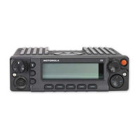
Motorola Astro XTL 5000 User Manual (162 pages)
Digital mobile radio
Table of Contents
-
Introduction
15-
-
Menu24
-
-
-

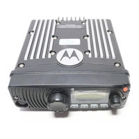
Motorola Astro XTL 5000 User Manual (158 pages)
Digital Mobile Radio W4, W5, W7, W9 Control Heads
Table of Contents
-
Introduction
23-
-
Alert Tones30
-
-
Motorola Astro XTL 5000 User Manual (120 pages)
Digital Mobile Radio O5 Control Head
Table of Contents
-
Introduction
11-
Alert Tones18
-
-

Motorola Astro XTL 5000 User Manual (134 pages)
Digital Mobile Radio
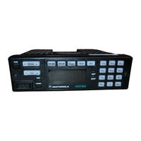
W3 Control Head
Table of Contents
-
Disclaimer10
-
-
Motorola Astro XTL 5000 Installation Manual (60 pages)
Motorola Astro XTL 1500 Digital Mobile Radio Installation manual
Table of Contents
Motorola Astro XTL 5000 Instruction Manual (38 pages)
Dual-Radio W3 Handheld Control Head System