Sign In
Upload
Manuals
Brands
Siemens Manuals
Relays
7SG11 Argus
Siemens 7SG11 Argus Manuals
Manuals and User Guides for Siemens 7SG11 Argus. We have
3
Siemens 7SG11 Argus manuals available for free PDF download: Manual, Technical Manual
Siemens 7SG11 Argus Manual (241 pages)
Brand:
Siemens
| Category:
Relays
| Size: 4.33 MB
Table of Contents
Reyrolle Protection Devices
2
Table of Contents
2
Ordering Information - 7Sg1113 Argus 1
6
Document Set
18
User Manual
19
Table of Contents
20
Section 1: Relay Description
22
Overview
22
Hardware
22
Functionality
24
Figure 1-1 Overcurrent Characteristics
25
Section 2: Operation Guide
30
User Interface Operation
30
Technical Reference
30
Figure 2-1 Menu Structure for Argus 1, 2, 4 and 6 Relays
31
Operation Using Reydisp Evolution (IEC 60870-5-103 Comms Only)
33
Section 3: Installation
34
Unpacking, Storage and Handling
34
Recommended Mounting Position
34
Relay Dimensions
34
Wiring
34
Fixings
35
Ancillary Equipment
35
Table 3-1 Wire Crimp Sizes
35
Section 4: Commissioning
36
Before Testing
36
Tests
37
Table 4-1 IDMTL Timing Characteristic (Time in Seconds)
38
Table 4-2 Connections for Directional Polarity
40
Figure 4-1 Directional Earth Fault Boundary System Angles
41
Figure 4-2 Directional Phase Fault Boundary System Angles
41
Table 4-3 Limits of Operate Pick-Up Relay Angle Boundaries
41
Putting into Service
45
Commissioning Record Tables
46
Table 4-4 Pick-Up/Drop-Off Results
46
Table 4-5 Timing Characteristic Results
46
Table 4-6 Lowset Setting Results
46
Table 4-7 Highset 1 Setting Results
47
Table 4-8 Highset 2 Setting Results
47
Table 4-9 Lowset Timing Results
47
Table 4-10 Highset 1 Timing Results
47
Table 4-11 Highset 2 Timing Results
47
Table 4-12 Pick-Up/Drop-Off Results for SEF/REF
48
Table 4-13 SEF/REF Timing Results
48
Table 4-14 Pick-Up/Drop-Off Results for CBF Level Detector
48
Table 4-15 Circuit Breaker Fail Timing Results
48
Table 4-16 Directional Boundaries of Operation
49
Table 4-17 Auto-Reclose Sequences and Settings
49
Table 4-18 Primary Injection Results
50
Figure 4-3 Secondary Injection Test Circuit
51
Figure 4-4 Directional Test Circuit
51
Figure 4-5 Two-Out-Of-Three Directional Test Circuit
51
Figure 4-6 Phase to Earth Primary Injection Test Circuit
51
Figure 4-7 Phase to Phase Primary Injection Test Circuit
51
Figure 4-8 Resultant Applied Voltages and Currents for a Simulated Earth Fault Condition Using Load Current
52
Section 5: Testing and Maintenance
53
Periodic Tests
53
Maintenance
53
Troubleshooting
53
Table 5-1 Troubleshooting Guide
53
Section 1: Performance Specification/Section 2: Functional Description
57
List of Figures
59
List of Tables
59
Section 1: Performance Specification
61
General
61
Conformity
61
Dimensions and Weights
61
Reference
61
Energising Quantities
62
Characteristic Energising Quantities
62
Auxiliary Energising Quantity
63
Functional Performance
64
Phase-Fault Overcurrent Protection
64
Directional Characteristics
66
Earth-Fault Overcurrent Protection
66
Sensitive/Restricted Earth-Fault Protection
66
Circuit Breaker Fail
67
Auto-Reclose
68
Communication Interface
68
Instrumentation
68
Real Time Clock
68
Output Contacts
64
Environmental Performance
68
General
68
Immunity
69
Emissions
70
Mechanical
70
Section 2: Functional Description
75
Introduction
75
Document Organisation
76
Models
76
Configuration
77
Settings Groups
77
System Frequency
77
Current and Voltage Inputs
78
Direction Tags
79
General Alarms
79
Identifier
79
Default Instruments
80
Password
80
Real Time Clock
80
Phase-Fault and Earth-Fault Overcurrent
81
Delay Characteristic Element
81
Instantaneous Elements
82
Flashing (Pecking) Fault Protection
84
Sensitive Earth-Fault and Restricted Earth-Fault
85
High Impedance Restricted Earth-Fault Scheme
86
Primary Equipment Fail Protection
86
Circuit Breaker (Trip) Fail Protection
86
Close Fail
87
Current Transformer Failure
87
Trip Circuit Supervision - for Details See Sections 2.10 and 3.8
88
Cold Load Protection
88
Directional Control
89
Polarisation
89
Two-Out-Of-Three Gate
90
Voltage Memory
90
Voltage Protection
91
Auto-Reclose
92
Auto Reclose Sequences
93
Control Inputs
98
Frequent Operations Counter
99
Hot (Live) Line Working
99
Trip Circuit Supervision
100
Status Inputs and Relay Outputs
100
Communications
102
Data Storage
102
Event Storage
102
Fault Data Record
102
Waveform (Disturbance) Records
103
Maximum Demand Function
104
Maintenance
105
Circuit Breaker Operations
105
Output Relay Test
106
Internal Supervision
107
Linesman Mode
107
Section 3: Application Notes
109
Directional Protection
109
Parallel or Ring Feeder Protection
109
Selection of Characteristics
109
Reset Delay
109
Sensitive Earth-Fault Protection
110
Blocking Schemes
111
Busbar Zone Protection
112
High Impedance Restricted Earth-Fault Protection
113
Auto-Reclose Applications
115
Reclaim Time Setting
115
Reclose Time Setting
115
Sequence Auto-Reclosing
116
Shots to Lockout Setting
116
Circuit Breaker Fail Protection
115
Trip Circuit Supervision
116
Output Relays
117
Post-Fault Analysis
117
Events, Fault and Waveform Records
117
Fault Triggers
117
Reydisp (IEC 60870-5-103)
118
Waveform Triggers
118
Auxiliary Supply /Binary Input Voltage | | | | | |
134
2 Pole Phase-Fault and Sensitive/Restricted Earth-Fault (SEF/REF) D| | | |
136
Table of Contents
163
110/220 V DC Auxiliary, 48 V Binary Input ¹) 3 | | | | |
165
Contents
198
Section 4: Communication Interface
119
Comms Protocol Setting
119
Introduction
119
Medium
119
Physical Connection
119
Recommended Cable
119
Baud Rate
120
Comms Parity
120
IEC Class II Measurands
120
IEC Class II Scaling
120
IEC Class II Update Period
120
Line Idle
120
Network Topology
120
Relay Address
120
Settings
120
Connecting a Modem to the Relay(S)
121
Data Echo
121
Modems
121
Setting the Remote Modem
121
Connecting to the Remote Modem
122
Introduction - Modbus RTU
123
Medium
123
Network Topology
123
Recommended Cable
123
Auxiliary Supply /Binary Input Voltage 24/30/48 V DC Auxiliary, 30 V Binary Input
133
V DC Auxiliary, 30 V Binary Input
134
V DC Auxiliary, 48 V Binary Input
135
Housing Size
136
Argus 1 Diagrams and Parameters
137
Argus 2 Diagrams and Parameters
160
V DC Auxiliary, 110 V Low Burden Binary Input
165
V DC Auxiliary, 220 V Low Burden Binary Input
166
The Copyright and Other Intellectual Property Rights in this Document, and in any Model or Article Produced from It
197
Hardware Release History
198
Software Release History
198
Contents/List of Figures
199
Contents
199
List of Figures
199
Section 1: Variants
200
Section 2: Settings
202
List of Figures
217
Contents
220
List of Figures
232
Section 3: IEC 60870-5-103 & Modbus RTU Definitions
209
IEC 60870-5-103 Definitions
209
Protection
217
Section 4: Application Diagrams
217
Argus 6 Diagrams and Parameters
219
Hardware Release History
220
Siemens Protection Devices Limited
220
Software Release History
220
Section 1: Variants
222
Section 2: Settings
224
Protection
232
Section 3: IEC 60870-5-103 Definitions
232
Advertisement
Siemens 7SG11 Argus Technical Manual (97 pages)
Argus 8
Brand:
Siemens
| Category:
Relays
| Size: 2.27 MB
Table of Contents
Reyrolle Protection Devices
2
Table of Contents
2
Description of Operation
3
Introduction
6
Relay Settings
6
Table 1 - Argus 8 - 2 Pole Variants
7
Table 2 - Argus 8 - 3 Pole Variants
7
Communication Interface
8
Table 3 - Output Relay Types
8
Applications Guide
10
Figure 1 - Voltage Element
10
Protection Functions
10
Voltage Blocking Element
10
Voltage Elements
10
Figure 2 - NPS Overvoltage Element
11
Figure 3 - NVD Overvoltage Element
11
Frequency Elements
11
NPS Overvoltage Elements
11
NVD Overvoltage Elements
11
External Tripping
12
Figure 4 - Frequency Element
12
Metering
12
Other Features
12
Two Systems Connection
12
Data Storage
13
Event Records
13
Waveform Records
13
Communications
14
Fault Data Records
14
Default Instrument Screens
15
General Alarm Screens
15
Multiple Settings Groups
15
Password Feature
15
Keypad
16
LED Indications
16
Liquid Crystal Display
16
Navigating the Menu System
16
Trip Circuit Supervision
16
User Interface
16
Table 4 - Connection Table (E4 Versions)
18
Table 5 - Connection Table (E6 Versions)
19
Table 6 - Event Codes
21
Figure 5 - Display Menu Structure
22
Maintenance
22
Siemens Protection Devices Limited
23
Table of Contents
24
Auxiliary Energising Quantity
25
DC Power Supply
25
DC Status Inputs
25
Characteristic Energizing Quantity
25
General
25
Accuracy
26
Overvoltage Element
26
Undervoltage Element
27
Neutral Voltage Element
27
NPS Overvoltage Element
27
Overfrequency Element
27
Underfrequency Element
28
DTL Timing Elements
28
Accuracy Reference Conditions
26
Setting Ranges
26
Accuracy General
28
Accuracy Influencing Factors
28
Burdens
28
Thermal Withstand
28
Environmental Withstand
29
General
29
Immunity
29
Emissions
30
Mechanical
30
The Copyright and Other Intellectual Property Rights in this Document, and in any Model or Article Produced from It
32
Output Contacts
29
Table of Contents
33
System Config Menu
34
Voltage Menu
35
System a Menu
36
System B Menu
36
Frequency Menu
37
Neutral Voltage Menu
37
NPS Overvoltage Menu
37
P Relay Config Menu
38
Status Config Menu
39
Comms Interface Menu
40
Data Storage Menu
40
CB Maintenance Menu
41
The Copyright and Other Intellectual Property Rights in this Document, and in any Model or Article Produced from It
42
The Copyright and Other Intellectual Property Rights in this Document, and in any Model or Article Produced from It
50
Table of Contents
51
General Information
52
Relay External Connections
52
Voltage Blocking Element
52
Output Contact Delay Time
53
Setting DTL Times
53
Voltage Element Hysteresis
54
Trip Circuit Supervision
54
Introduction
52
Application of Functions
54
Undervoltage Protection
54
Overvoltage Protection
55
Neutral Voltage Displacement Protection
55
NPS Overvoltage Protection
56
Frequency Protection
56
The Copyright and Other Intellectual Property Rights in this Document, and in any Model or Article Produced from It
66
Table of Contents
67
Fixings
68
Crimps
68
Panel Fixing Screws
68
Communications
69
Recommended Mounting Position
68
Relay Dimensions
68
Unpacking, Storage and Handling
68
Ancillary Equipment
69
The Copyright and Other Intellectual Property Rights in this Document, and in any Model or Article Produced from It
72
Table of Contents
73
Introduction
74
Required Test Equipment
74
Commissioning Tests
75
Inspection
75
Insulation
75
Wiring Check
75
Auxiliary Supply Check
75
Energising the Relay
75
Visual Inspection
76
Precautions
76
Status Input Tests
76
Output Relay Tests
77
Voltage Input Tests
78
Applying Settings
78
Optional Test
78
Under/Over Voltage Element
78
Putting into Service
79
On-Load Testing
79
Final Checks
79
Trouble Shooting
80
The Copyright and Other Intellectual Property Rights in this Document, and in any Model or Article Produced from It
84
Siemens 7SG11 Argus Manual (23 pages)
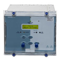
Overcurrent Protection Relay, Reyrolle Protection Devices
Brand:
Siemens
| Category:
Other
| Size: 1.64 MB
Table of Contents
Monitoring Functions
2
Function Overview
2
Description of Functionality
3
Technical Data
4
Inputs and Outputs
4
Electrical Tests
5
Case Dimensions
8
Connection Diagram
9
Typical Applications
10
Advertisement
Advertisement
Related Products
Siemens 7SG12 DAD-N
Siemens 7SG164 Ohmega 400 Series
Siemens 7SG16 Ohmega 402-60
Siemens 7SG1641 Ohmega 402 60
Siemens Argus 7SG116
Siemens SIPROTEC 7SA511
Siemens 7SR45 Argus
Siemens SIPROTEC 7SJ62
Siemens 7SR23 DAD
Siemens SIPROTEC 7SJ81
Siemens Categories
Industrial Equipment
Controller
Control Unit
Oven
Washer
More Siemens Manuals
Login
Sign In
OR
Sign in with Facebook
Sign in with Google
Upload manual
Upload from disk
Upload from URL