Sign In
Upload
Manuals
Brands
Siemens Manuals
Relays
7SR45 Argus
Siemens 7SR45 Argus Manuals
Manuals and User Guides for Siemens 7SR45 Argus. We have
5
Siemens 7SR45 Argus manuals available for free PDF download: User Manual, Device Manual, Manual, Quick Reference
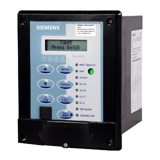
Siemens 7SR45 Argus User Manual (120 pages)
Self Powered/Dual Powered Non-Directional Overcurrent and Earth Fault Relay
Brand:
Siemens
| Category:
Other
| Size: 6.88 MB
Table of Contents
Table of Contents
5
Description of Operation
4
Siemens Protection Devices Limited
7
Chapter 1 - 7SR45 Description of Operation
9
Open Source Software
9
Section 1: Introduction
10
Current Transformer Circuits
10
Description
10
External Resistors
10
Ordering Options
11
Figure 1-1 Functional Diagram of 7SR45 Argus Relay
12
Functional Diagram
12
Figure 1-2 Terminal Diagram of Self Powered (7SR4501-Xga10-1AA0) and
13
Terminal Diagram
13
Figure 1-3 Terminal Diagram of Self Powered (7SR4501-Xgb10-1AA0) and
14
Figure 1-4 Terminal Diagram of Dual Powered (7SR4501/7SR4503-X[H/J]B10-1AA0) Non-Directional Overcurrent and Earth Fault Relay with Flag
14
Figure 1-5 Terminal Diagram of Dual Powered (7SR4502/7SR4504) Non-Directional Overcurrent and Earth Fault Relay with Flag
15
Section 2: Hardware Description
16
Figure 2-1 7SR45 Argus Relay Front Fascia with Flag Output
16
Front Fascia
16
Front Fascia with Flag Output
16
General
16
Figure 2-2 7SR45 Argus Relay Front Fascia Without Flag Output
17
Front Fascia Without Flag Output
17
Power Supply Unit (PSU)
17
Connectors
18
Connectors for Self and Dual Powered Relay Variant
18
Figure 2-3 7SR45 Argus Relay Connectors with 4 BI and 4 BO
18
Figure 2-4 7SR45 Argus Relay Connectors with 2 BI and 2 BO
19
Figure 2-5 7SR4501/7SR4502/7SR4503 Argus Self Powered Relay LED Indication Label
19
Operator Interface
19
Figure 2-6 7SR4502/7SR4504 Argus Dual Powered Relay LED Indication Label (with Flag)
20
Relay Information
20
Figure 2-7 Warning Symbols
21
Liquid Crystal Display (LCD)
21
Figure 2-8 Relay LCD
22
Keypad
22
Light Emitting Diode (LED)
23
Local Flag
23
Home Screen
24
Password Protection
24
Software Version Menu
24
Alarm Alert
25
Alert Screen
25
Fault Alert (Trip Alert)
25
Info Alert
25
Parameter Edit Screen
26
Figure 3-1 Logic Diagram: Instantaneous Overcurrent Element
27
Instantaneous Overcurrent Protection (50)
27
Section 3: Protection Functions (50, 51, 50N, 51N, 50G, 51G, 50LC)
27
Figure 3-2 Logic Diagram: Time Delayed Overcurrent Element
28
Time Delayed Overcurrent Protection (51)
28
Figure 3-3 Logic Diagram: Instantaneous Derived Earth Fault Element
30
Instantaneous Derived Earth Fault Protection (50N)
30
Figure 3-4 Logic Diagram: Time Delayed Derived Earth Fault Protection
31
Time Delayed Derived Earth Fault Protection (51N)
31
Figure 3-5 Logic Diagram: Instantaneous Measured Earth-Fault Element
33
Instantaneous Measured Earth Fault Protection (50G)
33
Figure 3-6 Logic Diagram: Time Delayed Measured Earth Fault Element
34
Time Delayed Measured Earth Fault Protection (51G)
34
Figure 3-7 Logic Diagram: 50LC Overcurrent Element
36
Switch-On-To-Fault (50LC/SOTF)
36
Figure 3-8 Operating Time for Switch-On-To Fault with Binary Outputs
37
Figure 3-9 Operating Time for Switch-On-To Fault with Pulse Output
37
General Alarm
38
Reset LED, Trip Flag Indication and Binary Outputs
38
Figure 3-10 Reset Leds Outputs: Reydisp Software Input Matrix
39
Figure 3-11 Reset Flags
39
Reset through Binary Input
39
Reset through Rear Communication Protocol
39
Reset Using Reydisp Software
39
TEST/RESET► Key
39
Binary Inputs
40
Current Inputs
40
Figure 3-12 Binary Input Logic
40
Binary Output Configuration
42
Binary Output Matrix
42
Binary Outputs
42
Figure 3-13 Binary Output Logic
42
Binary Output Operations
43
BO Trip/Reset on Battery/Usb
43
BO Trip/Reset on CT Input or Auxiliary Voltage
43
Auxiliary Voltage
44
CT Input
44
Modes of Operation
44
Pulse Output
44
Remote Flag Output
44
Figure 3-14 Sensitivity for Single Phase Fault with Binary Output
45
Figure 3-15 Sensitivity for Single Phase Fault with Pulse Output
45
Battery
46
Usb
46
Internal Relay Failure (IRF)
47
Low Battery Status Indication
47
Maintenance Mode
47
Output Test
47
Self Monitoring
47
Sleep Mode
47
Data Storage
48
Fault Records (Trip Log)
48
Event Records (Event Log)
49
Operating Mode
49
Real Time Clock
49
Password Feature
50
Settings Groups
50
Battery
51
Firmware Update
51
Section 1: Introduction/Section 2: Setting & Configuring the Relay Using Reydisp Evolution
53
Chapter 2 - 7SR45 Settings & Instrument Guide
54
Section 1: Introduction
54
Operation Guide
54
Relay Menus
54
Setting Mode
54
User Interface Operation
54
Instrument Mode
55
Fault Data Mode
57
Section 2: Setting & Configuring the Relay Using Reydisp Evolution
58
Front USB Connection
58
Physical Connection
58
Rear RS485 Connection
58
Configuring Relay Serial Data Communication
59
Connecting to the Relay for Setting Via Reydisp
60
Section 1: Performance Specification
62
Chapter 3 - 7SR45 Performance Specification
63
Indication of Conformity
63
Section 1: Performance Specification
63
Technical Specifications
63
Environmental Performance
67
Performance Specification
73
Table of Contents
76
Section 1: Introduction
77
Chapter 4 - 7SR45 Data Communications Definitions
78
Introduction
78
Section 2: Physical Connection
78
USB Interface
78
RS485 Interface
79
Section 3: Glossary
81
Section 4: IEC 60870-5-103 Definitions
82
Application Service Data Unit (ASDU) Type
82
Cause of Transmission
82
Introduction
82
Point List
82
Event Function (FUN) & Information (INF) Numbers
83
Measurands
85
Section 5: Modbus Definitions
86
Float_Ieee_754
86
Fp_32Bits_3Dp
86
Introduction
86
MODBUS Register Data Types
86
Uint32
86
Event
87
Uint16
87
Eventcount
88
Time_Meter
92
Section 1: Current Transformer Requirements
112
Time Delayed Overcurrent (51/51G/51N)
116
Selection of Overcurrent Characteristics
117
Chapter 7 - 7SR45 Applications Guide
118
Reset Delay
118
Instantaneous Overcurrent (50/50G/50N)
119
Advertisement
Siemens 7SR45 Argus Manual (102 pages)
Reyrolle
Brand:
Siemens
| Category:
Relays
| Size: 6.45 MB
Table of Contents
Preface
3
Open Source Software
7
Table of Contents
9
1 First Steps
13
Unpacking, Repacking, Returning, Transporting, and Storing
14
Incoming Inspection
16
Electrical Inspection
17
2 Installing the Device
19
Drilling Patterns and Device Dimensions
20
Mounting Instructions
23
Installing Devices
24
Earthing and Connecting Devices
25
Terminal Lugs Specification
26
Environmental Protection Hints
27
3 Handling of the Device
29
Battery Replacement
30
Installing Transparent
33
Installing Surface Mounting Bracket
37
Post Installation and Commissioning
40
Replacement of the Device
44
4 Using the Relay Fascia
45
General
46
Home Screen
47
Software Version Menu
48
Overview of Operator Elements and Display Elements
49
Structure of the Menu
52
Relay Menu
52
User Interface Operation
52
Setting Mode
53
Instrument Mode
53
Fault Data Mode
54
Menu Tree
55
Notification Alerts
56
Fault Alert (Trip Alert)
56
Alarm Alert
56
Info Alert
56
Parameter Edit Screen
57
5 Using Reydisp Evolution
59
General
60
Connecting to the Relay for Setting Via Reydisp Evolution
62
6 In Service Operation
63
Overview
64
Safety Notes
65
Operation Options
66
General
66
Modes of Operation
67
Overview
67
Auxiliary Voltage
67
CT Input
67
Usb
70
Battery
70
Sleep Mode
71
Low Battery Status Indication
71
Online Operation Using Reydisp
73
Reydisp Evolution Configuration Software
73
Indications
74
General
74
Reading Indications from the PC with Reydisp Evolution
74
Displaying Indications
75
Resetting Stored Indications
75
Logs
77
Data Storage
77
Saving and Deleting the Logs
78
General Alarm
78
Edit Measured and Metered Values
79
Overview of Measured and Metered Values
79
Reading Measured Values and Metered Values
79
Change Device Settings
80
Settings Group Selection
82
7 Commissioning
83
Overview
84
Test Suite Integrated in the Device
85
Testing Protection Functions
85
Output Test
85
Initial Startup
86
Precommissioning Tests
87
Testing Readiness for Operation
88
8 Device Maintenance
89
Execute Checks
90
Protection-Function Test
90
Self Monitoring
91
General Information
93
Troubleshooting
94
Replace and Return Defective Device
95
Backup Device
95
Replacing a Device
95
Returning a Device
95
Firmware Update
96
9 Security Settings
97
Confirmation ID (Password Feature)
98
A Appendix
99
Revision History
100
Index
101
Siemens 7SR45 Argus Device Manual (118 pages)
Brand:
Siemens
| Category:
Relays
| Size: 5.44 MB
Table of Contents
Preface
3
Open Source Software
7
Table of Contents
9
Introduction
11
7SR45 Overcurrent and Earth Fault Relay Overview
12
Ordering Options
14
Device Functionality
17
Front Fascia
18
Liquid Crystal Display
19
Keypad
20
Light Emitting Diode (LED)
21
Local Flag
23
Relay Information
24
Binary Inputs
26
Binary Outputs
28
Pulse Output
31
Remote Flag Output
32
Reset LED, Trip Flag Indication, and Binary Outputs
33
Data Storage
36
Real Time Clock
37
Functions
39
Functions Available in the 7SR45 Device
40
Instantaneous Overcurrent Protection (50)
41
Instantaneous Overcurrent Protection
41
Time-Delayed Overcurrent Protection (51)
44
Time-Delayed Overcurrent Protection
44
Instantaneous Derived Earth Fault Protection (50N)
50
Time-Delayed Derived Earth Fault Protection (51N)
53
Instantaneous Measured Earth Fault Protection (50G)
58
Time-Delayed Measured Earth Fault Protection (51G)
61
Switch Onto Fault Protection (50LC/SOTF)
66
Thermal Overload Protection (49)
71
2Nd Harmonic Block/Inrush Restraint (81HBL2)
75
Technical Data
77
General Device Data
78
Instantaneous Overcurrent Protection (50)
80
Instantaneous Overcurrent Protection
80
Time-Delayed Overcurrent Protection (51)
81
Time-Delayed Overcurrent Protection
81
Instantaneous Derived Earth Fault Protection (50N)
82
Time-Delayed Derived Earth Fault Protection (51N)
83
Instantaneous Measured Earth Fault Protection (50G)
84
Time-Delayed Measured Earth Fault Protection (51G)
85
Switch on to Fault Protection (50LC/SOTF)
86
Thermal Overload Protection (49)
87
Thermal Overload Protection
87
2Nd Harmonic Block/Inrush Restraint (81HBL2)
88
Applications
89
Overview
90
Current-Transformer Requirements and Sample Calculations
91
Current-Transformer Requirements
91
Time-Delayed Overcurrent (51/51G/51N)
95
Overcurrent Characteristics
97
Selection of Overcurrent Characteristics
97
Reset Delay
97
Instantaneous Overcurrent (50/50G/50N)
98
Thermal Overload (49)
99
Thermal Overload
99
Inrush Response
101
Inrush Detector (81HBL2)
102
Functional Tests
103
Commissioning Notes
104
Before Testing
105
Safety
105
Sequence of Tests
105
Test Equipment
106
Use of Laptop Computer to Facilitate Testing
106
Applying Settings
107
A Appendix
109
Connection Examples for RMU Application
110
Connection Examples for Distribution Transformer Application
112
Connection Examples for Phase and CBCT Measurement
114
Connection Examples for Earth-Fault Application
115
Revision History
116
Index
117
Advertisement
Siemens 7SR45 Argus User Manual (68 pages)
Self Powered Overcurrent and Earth Fault Relay
Brand:
Siemens
| Category:
Relays
| Size: 1.53 MB
Table of Contents
Table of Contents
5
Description of Operation
4
Siemens Protection Devices Limited
7
Section 1: Introduction
9
Current Transformer Circuits
9
External Resistors
9
Description
9
Ordering Options
10
Functional Diagram
11
Figure 1-1 Functional Diagram of 7SR45 Self Powered Overcurrent and Earth Fault Relay
11
Terminal Diagram
12
Figure 1-2 Terminal Diagram of 7SR45 Self Powered Overcurrent and Earth Fault Relay
12
Section 2: Hardware Description
13
Operator Interface
13
Figure 2-1 LED Indication Label
13
Liquid Crystal Display (LCD)
14
Figure 2-2 Safety Symbols
14
Figure 2-3 Relay LCD
14
Keypad
15
Light Emitting Diode (LED)
16
Home Screen
16
Password Protection
16
Software Version Menu
17
Alert Screen
17
Fault Alert
17
Alarm Alert
17
Info Alert
17
Parameter Edit Screen
18
Section 3: Protection Functions (50, 51, 50N, 51N, 50G, 51G, 50LC)
19
Instantaneous Overcurrent Protection (50)
19
Figure 3-1 Logic Diagram: Instantaneous Overcurrent Element
19
Time Delayed Overcurrent Protection (51)
20
Figure 3-2 Logic Diagram: Time Delayed Overcurrent Element
20
Instantaneous Derived Earth Fault Protection (50N)
21
Figure 3-3 Logic Diagram: Derived Instantaneous Earth Fault Element
21
Time Delayed Derived Earth Fault Protection (51N)
22
Figure 3-4 Logic Diagram: Derived Time Delayed Earth Fault Protection
22
Instantaneous Measured Earth Fault Protection (50G)
23
Figure 3-5 Logic Diagram: Instantaneous Measured Earth-Fault Element
23
Time Delayed Measured Earth Fault Protection (51G)
24
Figure 3-6 Logic Diagram: Measured Time Delayed Earth Fault Element
24
Switch-On-To-Fault (50LC/SOTF)
25
Figure 3-7 Logic Diagram: 50LC Overcurrent Element
25
Figure 3-8 Operating Time for Single Phase Fault with Binary Output
26
Figure 3-9 Operating Time for Single Phase Fault with Impulse Output
26
General Alarm
27
Reset Leds Outputs
27
Binary Input
27
Reydisp Software
28
TEST/RESET► Key
28
Figure 3-10 Reset Leds Outputs: Reydisp Software Input Matrix
28
Figure 3-11 Reset Flags
28
Current Inputs
29
Binary Inputs
29
Figure 3-12 Binary Input Logic
29
Binary Outputs
30
Binary Output Matrix
30
Self Reset/Hand Reset
30
Binary Output Configuration
30
Figure 3-13 Binary Output Logic
31
Binary Output Operation
32
BO Trip/Reset on Battery Power and USB Power
32
BO Trip/Reset on CT Power
32
Impulse Output
32
Modes of Operation
32
CT Power
32
Figure 3-14 Sensitivity for Single Phase Fault with Binary Output
33
Figure 3-15 Sensitivity for Single Phase Fault with Impulse Output
33
USB Power
34
Battery Power
34
Sleep Mode
34
Low Battery Indication
34
Maintenance Mode
35
Output Test
35
Self Monitoring
35
Internal Relay Failure (IRF)
35
Data Storage
36
Fault Records (Trip Log)
36
Event Records (Event Log)
36
Real Time Clock
37
Battery
37
Firmware Update
37
The Copyright and Other Intellectual Property Rights in this Document, and in any Model or Article Produced from It
38
Table of Contents
39
Operation Guide
40
User Interface Operation
40
Relay Menus
40
Setting Mode
40
Instrument Mode
41
Fault Data Mode
42
Table of Contents
44
Section 1: Performance Specification
45
Indication of Conformity
45
Technical Specifications
45
Table 1-1 Technical Data Overview
45
Table 1-2 Sensitivity
45
Table 1-3 Mechanical Specifications
45
Table 1-4 Terminal Blocks
46
Table 1-5 Current Inputs
46
Table 1-6 Binary Inputs
46
Environmental Performance
47
Table 1-7 Binary Outputs
47
Table 1-8 Front Communication Port
47
Table 1-9 Data Storage
47
Table 1-10 Environment
47
Table 1-11 Mechanical Tests
47
Table 1-12 Electrical Tests
48
Table 1-13 Climatic/Environmental Tests
49
Table 1-14 Product Safety Test
50
Table 1-15 Real Time Digital Simulation Test (RTDS)
51
Table 1-16 Inrush Response Test (RTDS)
51
Performance Specification
52
Table 1-17 50 Instantaneous & DTL OC & EF
52
Table 1-18 51 Time Delayed OC & EF
52
Table 1-19 50LC/SOTF
52
Siemens 7SR45 Argus Quick Reference (2 pages)
Brand:
Siemens
| Category:
Relays
| Size: 0.33 MB
Advertisement
Related Products
Siemens Reyrolle 7SR46
Siemens Argus 7SR21
Siemens Argus 7SR11
Siemens Argus 7SR12
Siemens 7SR18 Solkor
Siemens 7SR10 Argus Series
Siemens 7SR23 DAD
Siemens 7SR17 Rho
Siemens Reyrolle 7SR5
Siemens 7SR158 Argus
Siemens Categories
Industrial Equipment
Controller
Control Unit
Oven
Washer
More Siemens Manuals
Login
Sign In
OR
Sign in with Facebook
Sign in with Google
Upload manual
Upload from disk
Upload from URL