Sharp AR-5316 Service Manual
Hide thumbs
Also See for AR-5316:
- Operation manual (80 pages) ,
- Service manual (56 pages) ,
- Software setup manual (16 pages)
Table of Contents
Advertisement
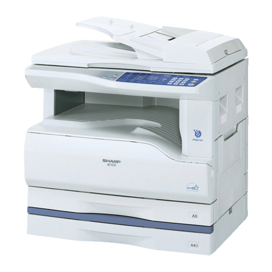
AR-5316
[ 1 ] NOTE FOR THIS SERVICE MANUAL . . . . . . . . . . . . . . . Refer to AR-M160
[ 2 ] SPECIFICATIONS . . . . . . . . . . . . . . . . . . . . . . . . . . . . . . . . . .AR-5316/5320
[ 3 ] CONSUMABLE PARTS. . . . . . . . . . . . . . . . . . . . . . . . . . . . . .AR-5316/5320
[ 4 ] EXTERNAL VIEWS AND INTERNAL STRUCTURES . . . . . .AR-5316/5320
[ 5 ] UNPACKING AND INSTALLATION . . . . . . . . . . . . . . . . . . . . .AR-5316/5320
[ 6 ] ADJUSTMENTS . . . . . . . . . . . . . . . . . . . . . . . . . . . . . . . . Refer to AR-M160
[ 7 ] SIMULATIONS . . . . . . . . . . . . . . . . . . . . . . . . . . . . . . . . . . . .AR-5316/5320
[ 8 ] USER PROGRAMS . . . . . . . . . . . . . . . . . . . . . . . . . . . . . . . .AR-5316/5320
[ 9 ] TROUBLE CODE LIST . . . . . . . . . . . . . . . . . . . . . . . . . . . Refer to AR-M160
[10] MAINTENANCE . . . . . . . . . . . . . . . . . . . . . . . . . . . . . . . . . . .AR-5316/5320
[11] DISASSEMBLY AND ASSEMBLY . . . . . . . . . . . . . . . . . . . Refer to AR-M160
[12] FLASH ROM VERSION UP PROCEDURE . . . . . . . . . . . Refer to AR-M160
[13] ELECTRICAL SECTION . . . . . . . . . . . . . . . . . . . . . . . . . . . . .AR-5316/5320
Parts marked with "
" are important for maintaining the safety of the set.
Be sure to replace these parts with specified ones for maintaining the safety and performance of the set.
AR-5320
(with option installed)
CONTENTS
SHARP CORPORATION
CODE : 00ZAR5320/A1E
DIGITAL COPIER
MODEL
This document has been published to be used for
after sales service only.
The contents are subject to change without notice.
AR-5316
AR-5320
Advertisement
Table of Contents

Related Manuals for Sharp AR-5316


Summary of Contents for Sharp AR-5316
- Page 1 [ 7 ] SIMULATIONS ........AR-5316/5320...
-
Page 2: Specifications
[1] NOTE FOR THIS SERVICE MANUAL This Service Manual describes only the items related to the AR-5316 and AR-5320. For the other items common with the AR-M160/M205, please refer to the AR-M160/205 Service Manual (Document code:00ZARM205/A1E). The table below shows which document(s) should be referred to for each section. -
Page 3: Consumable Parts
Vinyl bag Developer Developer 500K AR-202CD-C CD-C=SD-C*10 (Developer : Net Weight 400g) Drum kit Drum AR-202DR-C Drum fixing plate Note 1: The individual carton is printed with English and Chinese as well as the green mark. AR-5316/5320 CONSUMABLE PARTS 3-1... -
Page 4: External Views And Internal Structures
Right side cover Exit area Toner cartridge lock release lever (when the SPF is installed) (when the SPF is installed) Toner cartridge Roller rotating knob Fusing unit release levers Photoconductive drum Fusing unit paper guide AR-5316/5320 EXTERNAL VIEWS AND INTERNAL STRUCTURES 4-1... -
Page 5: Operation Section
INTERRUPT key / indicator Light and Dark keys / indicators PAPER SIZE ENTER key TRAY SELECT key AUTO IMAGE key / indicator Numeric keys # key START key / indicator CLEAR ALL key CLEAR key AR-5316/5320 EXTERNAL VIEWS AND INTERNAL STRUCTURES 4-2... -
Page 6: Unpacking And Installation
For example, if the tray's paper ENTER size setting is A4R, set "Setting Paper Size" to "A4-R". For more information, see "CONFIGURING THE PRINTER DRIVER" in the "Software Setup Guide". AR-5316/5320 UNPACKING AND INSTALLATION 5-1... -
Page 7: Entering The Simulation Mode
Main scanning magnification ratio adjustment SPF counter display SPF/RSPF mode sub scanning magnification ratio Paper feed counter display adjustment in copying Drum counter display Flash ROM program writing mode CRUM type display Standby mode fusing fan RPM setting P-ROM version display AR-5316/5320 SIMULATIONS 7-1... -
Page 8: Contents Of Simulations
Manual paper feed solenoid 2nd cassette jam lamp * 2nd cassette paper transport solenoid Machine jam lamp & 2nd cassette jam lamp * 3rd cassette transport solenoid Supported for the installed models only. Skipped for the models without installation. AR-5316/5320 SIMULATIONS 7-2... - Page 9 Scanner counter display The scanner counter value is displayed. (Alternate display by 3 digits)When the [Interrupt] key is pressed, the machine goes into the sub code input standby mode. When the [CA] key is pressed, the simulation is terminated. AR-5316/5320 SIMULATIONS 7-3...
- Page 10 Display lamp Setting mode Default AE mode lamp Normal temperature control (190°C or less) Low speed rotation TEXT mode Fusing temperature of 190°C or above High speed rotation Code number Setting Low speed rotation High speed rotation AR-5316/5320 SIMULATIONS 7-4...
- Page 11 Printing is made in 1 by 2 mode, where one line is printed and the following two liens are not printed, or in the grid pattern. Code number Pattern 1 by 2 Grid pattern White paper Black background Input disable for 4 ~ 99 Print data are made on A3 size. (A3 paper is preferable.) AR-5316/5320 SIMULATIONS 7-5...
-
Page 12: List Of User Programs
TEXT mode from 600 x 300 dpi to 600 x 600 dpi 2 (600dpi) 300dpi (high-quality mode). Scanning is slower when high-quality mode is used. *1 On models with a SPF. *2 On model with the two trays. AR-5316/5320 USER PROGRAMS 8-1... - Page 13 2 (Lower paper tray) paper tray reverts to the initial settings. 5 (Bypass tray) Default exposure mode Use this program to set "AUTO", "TEXT", or "PHOTO" as the default 1 (AUTO) exposure mode. AUTO 2 (TEXT) 3 (PHOTO) AR-5316/5320 USER PROGRAMS 8-2...
-
Page 14: Maintenance Table
PS roller Transport (paper exit) rollers Spring clutch Fusing section Upper heat roller Pressure roller Pressure roller bearing Upper separation pawl Lower separation pawl Cleaning pad Drive section Gears Belts Paper exit section Ozone filter*1 *1:Recommendable replacement time:50K(Letter,5%print) AR-5316/5320 MAINTENANCE 10-1... -
Page 15: Maintenance Display System
When a waste toner cartridge is removed from the machine, it must be put in a polyethylene bag to avoid scattering of toner. B. DV cartridge Do not shake or put up the developer cartridge. Otherwise developer may scatter. AR-5316/5320 MAINTENANCE 10-2... -
Page 16: Electrical Section
[13] ELECTRICAL SECTION 1. Block diagram AR-5316/5320 ELECTRICAL SECTION 13-1... -
Page 17: Actual Wiring Diagram
3. Actual wiring diagram ACTUAL WIRING DIAGRAM 1/7 35FE-BT-VK-N (WHITE) B7B-PH-K-S (RED) B18B-PHDSS-B (WHITE) B3B-PH-K-SX 24FMN-BTRK-A (WHITE) B3B-PH-K-BK (BLACK) (BLACK) B3B-PH-K-S B6B-PH-K-S (WHITE) (WHITE) 13FE-BT-VK-N (WHITE) 13FE-BT-VK-N IMSA-9610S- (WHITE) (BLACK) AR-5316/5320 ELECTRICAL SECTION 13-2... -
Page 18: Lead-Free Solder
LEAD-FREE SOLDER The PWB’s of this model employs lead-free solder. The “LF” marks indicated on the PWB’s and the Service Manual mean “Lead-Free” solder. The alphabet following the LF mark shows the kind of lead-free solder. Example: <Solder composition code of lead-free solder> Solder composition Solder composition code Solder composition... - Page 19 COPYRIGHT 2003 BY SHARP CORPORATION All rights reserved. All rights reserved. All rights reserved. Printed in Japan. Printed in Japan. Printed in Japan. No part of this publication may be reproduced, No part of this publication may be reproduced, No part of this publication may be reproduced,...