Table of Contents
Advertisement
Quick Links
OPERATION & MAINTENANCE MANUAL
Water-Cooled SCREW Chiller
Please read this installation manual completely for safety before installing the product.
The purpose of this manual is to keep the user safe and to prevent any property damage.
After reading this installation manual, please retain it for future reference thoroughly
Installation work must be performed in accordance with this installation manual by
authorized personnel only.
Model : RCWW, LCWW
www.lge.com
Advertisement
Table of Contents

Related Manuals for LG RCWW


Summary of Contents for LG RCWW
- Page 1 The purpose of this manual is to keep the user safe and to prevent any property damage. After reading this installation manual, please retain it for future reference thoroughly Installation work must be performed in accordance with this installation manual by authorized personnel only. Model : RCWW, LCWW www.lge.com...
- Page 2 For your records Staple your receipt to this page in case you need it to prove the date of purchase or for warranty purposes. Write the model number and the serial number here: Model number : Serial number : You can find them on a label on the side of each unit. Dealer’s name : Date of purchase :...
-
Page 3: Cautions For Safety _ Warning/Caution
- Improper wiring or installation may cause fire or electric shock. • Do not disassemble, repair or reconfigure the unit. - LG Electronics is not responsible for the any damage or loss from the arbitrary disassembly, repair or reconfigura- tion of the unit. - Page 4 1. CAUTIONS FOR SAFETY _ WARNING/CAUTION • Securely install the cover of control box and the panel. - If the cover and panel are not installed securely, dust or water may enter the unit and fire or electric shock may result. •...
-
Page 5: Caution
1. CAUTIONS FOR SAFETY _ WARNING/CAUTION • Do not vent refrigerant relief valves within a building. - Outlet from relief valves must be vented outdoors in accordance with the latest edition of ANSI/ASHRAE(American Na- tional Standards Institute/American Society of Heating, Refrigeration and Air Conditioning Engineers) 15 (Safety Code for Mechanical Refrigeration). - Page 6 - This make it possible to ensure proper machine performance and reduce the potential of tubing damage due to corrosion, scaling, erosion and algae. LG Electronics is not responsible for any damage caused by cooling water not treated or improperly treated.
- Page 7 1. CAUTIONS FOR SAFETY _ WARNING/CAUTION • Do not overcharge refrigerant to the system. - Refrigerant overcharging results in higher discharge pressure with higher cooling fluid consumption. Also it can damage the compressor and increase the power consumption. Also it can damage the compressor and increase the power consumption.
-
Page 8: Table Of Contents
TABLE OF CONTENTS Thank you for purchasing the Water Cooled Centrifugal Chiller of LG Electronics. Installation as instructed after reading this manual will ensure the safety, convenience and long lifetime of the unit. • Please read this manual carefully for the correct installation and proper operation of the Centrifugal Chiller unit. -
Page 9: Introduction
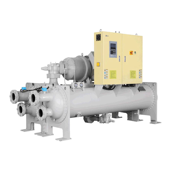
2. INTRODUCTION 2. INTRODUCTION 2-1. General Information This manual describes the installation of water cooled screw chiller with X30 controller applied. 2-2. System structure Figure 1 shows the general parts location and components of the water cooled screw chiller. The location of control panel, type of waterbox, directions of inlet and outlet of the chilled water and cooling water and some pipes may vary by model or customer order. -
Page 10: Nomenclature
2. INTRODUCTION 2-3. Nomenclature The model naming for screw chiller is done as follows. R : R-134a W : Water-cooled Compressor nominal Cooling/chilled water maxi- mum working pressures cooling only capacity in Tons(usRT) 10RT ⇨ 001 A : Chilled water 10kg/cm K : Water-cooled Cooling water 10kg/cm heat pump... -
Page 11: Main Unit Conversions
2. INTRODUCTION 2-5. Main unit conversions Temperature conversion table (°F ↔ °C) • °F = (9/5 x °C) + 32 • °C = 5/9 x (°F - 32) °F °C °F °C °F °C °F °C °F °C -17.2 -0.6 16.1 32.8 49.4... - Page 12 2. INTRODUCTION ↔ kg/cm Pressure conversion table (lb/in • lb/in = psi ex) 1 lb/in2 = 0.07030696 kg/cm lb/in kg/cm lb/in kg/cm lb/in kg/cm lb/in kg/cm lb/in kg/cm 5.695 0.070 2.883 8.507 11.32 5.765 0.141 2.953 8.577 11.39 5.836 0.211 3.023 8.648 11.46...
-
Page 13: 13 3. Structure Of Screw Chiller
3. STRUCTURE OF SCREW CHILLER 3. STRUCTURE OF SCREW CHILLER 3-1. Chiller cycle As shown in the chiller cycle figure below, the compressor discharges the high temperature/pressure refrigerant to the condenser through the exhaust outlet in gas state. The refrigerant in the gas state in the condenser flows out- side of the tube, while the cooling water flows inside of the tube. -
Page 14: Main Components Of Screw Chiller
3. STRUCTURE OF SCREW CHILLER 3-2. Main components of Screw chiller Compressor In this machine, semi-hermetic twin screw compressor, which was developed especially for air conditioning use, is installed. The structure of the compressor is shown in the picture below. Figure 5 Screw compressor Item Description... - Page 15 3. STRUCTURE OF SCREW CHILLER - Compression process As shown in Figure 6 below, during the rotation of the rotors, the absorbed gas is pushed to the discharge side. In other words, the V-shaped space formed between the male and female rotors is continuously moving to the discharge side. The gas sealed in the lobe space which is reduced by the discharge side is compressed, and the highly compressed gas at the end part is discharged to the oil separator.
- Page 16 3. STRUCTURE OF SCREW CHILLER Since the compressor should be started at the minimum load condition, the solenoid valve (capacity reducing sole- noid valve in stepless control system, or minimum load solenoid valve in the stage control capacity control system) should be kept open for 20-30 seconds before stopping or starting the compressor so that there is no oil left inside the cylinder when starting the compressor.
- Page 17 3. STRUCTURE OF SCREW CHILLER Heat exchanger Screw chiller heat exchanger is composed of evaporator and condenser, and has 2 shells which can be conveniently separated. To maximize the heat exchanging capability, the tube arrangement is optimized, and to prevent the de- crease of COP, refrigerant distributor is installed for the even distribution of liquid refrigerant in the entire tubes.
- Page 18 3. STRUCTURE OF SCREW CHILLER Oil flow switch The flow switch is installed at the water outlet nozzles in all equipment as the basic setting. The following figure shows the flow switch installed in the normal method. Num- Description Quantity Cover Insulation board Micro switch...
- Page 19 Depending upon the customer’s need, a different type of oil can be used, but in this case, the following items should be followed. - Use of a new oil should be consulted with LG Electronics first. - The oil inside the compressor should be cleaned before filling the new oil.
- Page 20 3. STRUCTURE OF SCREW CHILLER Safety devices The following devices are installed for safe operation and equipment protection(1 cycle). Installed Measurement Quan- Item Contents location objects tity This function stops the chiller when chilled water outlet temp. becomes 2.9°C or less to avoid the Chilled water Chilled water Chilled water inlet...
- Page 21 3. STRUCTURE OF SCREW CHILLER Installed Measurement Quan- Item Contents location objects tity 5 places includ- It shows up when the temperature sensor is not Temp. sensor ing chilled Temperature sensors connected or there is a defect in the temperature problem water nozzle.
-
Page 22: 22 4. Control System
4. CONTROL SYSTEM 4. CONTROL SYSTEM 4-1. Components of control panel and main parts Controller HMI with 7 inch Color LCD is composed as a graphic type. There are start/stop, control valve 2 and Compressor 2, compressor, lead/lag lamp, and chilled water / coolant flow lamp keys. - Page 23 4. CONTROL SYSTEM Schematic diagram of the main board(main control unit) - PCB Power supply unit POWER SUPPLY PART POWER Power filter FILTER Communication COMMUN Power input -ICATION Figure 15 Internal diagram of Master/Slave boards...
- Page 24 4. CONTROL SYSTEM Features of control unit The Control unit of LG chiller controls temperature, pressure, flow rate, current, voltage, power and capacity control valve using high capacity microprocessor. It is constructed to provide the high reliability chiller operation using LG's unique optimum control algorithm.
- Page 25 Controller system composition diagram Master, slave, HMI, Relay board communicates with RS485, and in one master/slave board, there are analog input(temp. 12 channel, current 10 channel), analog output(current 4 channel), digital input(20 channel), digital out- put(16 channel). Relay board controls Solenoid valve in 2 comp. PT100 INPUT UART...
- Page 26 4. CONTROL SYSTEM Control panel - Standard type * The above configuration may change according to design enhancement, type, or user convenience, so please refer to the approved drawing for details.
- Page 27 4. CONTROL SYSTEM Control panel component layout - Standard type Micom(Master Board) Micom(Slave Board) Relay(KM1~3) Fuse SMPS Terminal Block(TB) Noise Filter(NF) Fiqure 17. control panel TAG NAME Main power(for wiring) circuit breaker Micom power protection Noise Filter SMPS Control power supply Transformer Fuse Control power protection fuse Realy...
- Page 28 4. CONTROL SYSTEM Optional parts related controller BACnet converter Our controller basically supports Modbus communication protocol. If the higher level communication protocol is BACnet, you need to apply a separate BACnet converter to change the protocol. Communication converter is attached inside the control panel. Please refer to the following table for meaning and description of each lamp.
-
Page 29: Outside View Of Startup Panel - Stan
4. CONTROL SYSTEM 4-2. Outside view of Startup panel - Standard Type Since the starter panel has various layouts based on starter method, option, etc., please refer to the drawing provided together with the product. h The above configuration may change according to design enhancement, type, or user convenience, so please refer to the approved drawing for details. -
Page 30: Basic Control Algorithm
Unique P(proportional), I(integral), and D(differential) algorithms are applied to chilled water temperature control. Compared to the conventional method, it allows optimal control by minimizing time to approach the target value, re- maining deviation, Under-Shoot and Over-Shoot during initial startup and automatic/manual conversion of operation. LG’s New Control Algorithm General Control... -
Page 31: Bms Support Function
4. CONTROL SYSTEM 4-4. BMS support function Screw chiller’s basic communication protocol is Modbus protocol, and it is compatible with the higher level communi- cation methods. Communication protocol support • Communication method - Basic: RS-485, Ethernet(Optional) • Protocol - Basic: MODBUS - Option: BACnet, TCP/IP Figure 18 Detailed diagram of BMS... -
Page 32: Control Screen (Product Function
4. CONTROL SYSTEM 4-5. Control screen (Product function) Controller menu • User setting User setting Expansion valve setting System information(output) Account management Operation mode setting Expansion valve setting A Chilled water pump operation Management No. 1 Control mode setting Expansion valve setting B Abnormal status Management No. - Page 33 4. CONTROL SYSTEM • System setting Control information setting Abnormal condition setting Sensor calibration Sensor setting Control calculation period Chilled water temperature lower limit Chilled water inlet temperature Evaporator pressure sensor Control temperature dead band Compressor discharge temperature - high temperature Chilled water outlet temperature Condenser pressure sensor Motor rated current...
-
Page 34: Screw Chiller Timing Sequence
4. CONTROL SYSTEM 4-6. Screw Chiller Timing Sequence – Run & Stop... - Page 35 4. CONTROL SYSTEM Menu operation method and operation panel nomenclature The Display of screw chiller's control unit consists of; basic screen where present operation can be checked, and main menu which user can use conveniently for user setting, problem/warning information check, and system menu which is for sensor setting and system pertain item setting.
- Page 36 4. CONTROL SYSTEM Names of operation unit Name Description It is the color LCD(Liquid Crystal Display) showing operation information and status LCD screen as in text(Korean, English, Chinese) or animation graphic. It is the key to operate menu displayed on the LCD, such as, selection of the display- ing screen or setting of operation condition, etc.
- Page 37 4. CONTROL SYSTEM Names of color LCD screen display parts Operation method selection display Operation mode selection display Current menu & present time display Machine type selection display Displayed items Message display Key menu bar Figure 20 LED screen ① Operation mode selection display There are 3 operation modes, the first is Local operation to operate directly at the site, the second is Scheduled operation to operate automatically following the reserved time and the third is Remote operation to operate from a remote place.
- Page 38 4. CONTROL SYSTEM Basic screen It is the screen displaying input value and calculated output value status of each sensor attached to the main body of the screw chiller. It shows up as the initial screen when the micom's power is turned on. 1) Main - Movement path : Figure 21 Main screen...
- Page 39 4. CONTROL SYSTEM 3) Condenser - Movement path : Figure 23 Condenser screen * It shows the condenser animation screen and its relevant data. 4) Compressor - Movement path : Figure 24 Compressor screen * It shows the compressor animation screen and its relevant data.
- Page 40 4. CONTROL SYSTEM 5) History - Movement path : Figure 25 Operation history screen * It shows operation data, operation history and problem history data. 6) Menu - Movement path : Figure 26 Menu screen * It shows Menu screen...
- Page 41 4. CONTROL SYSTEM Screen display item list 4: Items that can be displayed High Display boundary Remark pressure pressure Chilled water inlet temperature -40.0~140.0 °C Chilled water outlet temperature -40.0~140.0 °C Cooling water inlet temperature -40.0~140.0 °C Cooling water outlet temperature -40.0~140.0 °C Compressor suction temperature -40.0~140.0 °C...
- Page 42 4. CONTROL SYSTEM 7) Main menu • Main menu can be classified into User Setting and System Setting as shown in the figure below. - User setting, interlock operation setting, scheduled operation setting or system information can be set by any user.
- Page 43 4. CONTROL SYSTEM - Main menu items in detail Displayed item Usage Menu for user to set values required for chiller operation, such as, control tempera- User setting ture or PID. Interlock operation setting Menu to set items used in Dual Compressor Menu to set time to automatically Run /Stop the chiller, and temperature by time System information period...
- Page 44 4. CONTROL SYSTEM User setting - Movement path : Use buttons to move, and when you select a menu, you can change the set values. Figure 28 User setting menu Operation mode setting screen consists of a menu to select the operation mode classified as Local, Scheduled and Remote, and another menu to select ice making mode or air conditioning mode.
- Page 45 4. CONTROL SYSTEM (4) Setting display screen Standard set Setting possible Item Setting boundary Setting unit value time Local/Scheduled Operation mode setting Local Always /Remote Air conditioning Control mode setting Always (*) /Ice making conditioning Chilled water outlet temperature 3.0 °C~ 30.0 °C 7.0 °C Always Ice maker outlet temperature...
- Page 46 Target value Target value <Conventional control method> <New P. I. D control by LG> Figure 29 Control method comparison (1) Chilled water outlet temperature The menu is for setting P. I. D control temperature of the chilled water outlet in air conditioning operation.
- Page 47 - Operation is possible only when the inverter is mounted on the user's MCC(MOTOR CONTROL CENTER) panel. This function is optional. Please contact LG Electronics for details before using. - The output of the cooling tower fan control is 4~20 mA at the micom.
- Page 48 4. CONTROL SYSTEM Interlock operation setting - Movement path : The method of use is the same as in "2) User setting". Figure 30 Interlock operation setting screen (1) Interlock mode setting items 'Menu/Interlock operation setting' items are displayed when the screw chiller is set to operate with 2 compres- sors.
- Page 49 4. CONTROL SYSTEM - Selecting interlock conversion method In interlock operation, this screen is to set whether the Main/Subordinate conversion should be done be done either by automatic or manual. In case the automatic conversion is selected, the conversion between the main and subordinate is automatically ex- ecuted when the deviation between the run hours of Compressor 1 and those of Compressor 2, which are counted in 'Run information check/Run stop information', reaches the hour value set in 'Interlock conversion time'.
- Page 50 4. CONTROL SYSTEM Scheduled operation setting - Movement path : The method of use is the same as in "2) User setting". Figure 31 Scheduled operation setting screen Figure 32 Schedule setting example screen * For setting method, please refer to "Example)". Example) ①...
- Page 51 4. CONTROL SYSTEM System information - Movement path : Figure 33 System information The screen displays the version of the program applied to the MICOM(Master, Slave and Display). "Program version No." is shown for follow-up service and is useful for trouble shooting in case there is a problem in MICOM. (1) Year, Month, Day, Day of the week, Hour, Minute and Second Here, you can set the date and hour.
- Page 52 4. CONTROL SYSTEM - Movement path : Move to Main/Evaporator/Con- Screen display button for denser/Compressor screen Compressor 2 status Figure 34 Input status check screen Displayed item Display status Contact point status Remark Chilled water flow interlock ON/OFF When in the ice making mode: Circuit closed Chilled water pump interlock ON/OFF When run signal input is made: Circuit closed...
- Page 53 4. CONTROL SYSTEM (6) Output status check This menu displays ON(=circuit closed)/OFF(=circuit open) status of the digital output port and the status of ana- log output. The menu is constructed for checking the output of the micom's internal calculation. In case the actual output is different from that in the menu, the status of micom's board and wiring should be checked.
- Page 54 4. CONTROL SYSTEM Displayed item Display status Contact point operation status Remark Selecting ice making mode ON/OFF When in the ice making mode: Circuit closed Refrigerant shut off control valve ON/OFF When valve is operated: Circuit closed Operation status ON/OFF When run input is made: Circuit closed For customer S operation 2...
- Page 55 4. CONTROL SYSTEM <Timer display items> Display item Display range Initial value(reference setting) Chilled water pump stop delay timer 0~1,800 Cooling water pump startup delay timer 0~60 Cooling water pump stop delay timer 0~180 Chilled water flow check timer 0~60 Valve open limit timer 1 0~600 Valve open limit timer 2...
- Page 56 4. CONTROL SYSTEM Sensor calibration The value of each sensor can be calibrated. The calibration ranges are; -5°C~5°C for temperature, -2kg/cm ~2kg/cm for pressure, -50m /h~50m /h for flow rate, - 200~200A/V/KW for current, voltage and power. - Movement path : Figure 37 Sensor screen...
- Page 57 4. CONTROL SYSTEM Control information setting This menu is for setting the basic control values of the chiller. If you move cursor to an item which you want to set in the menu bar, and press 'Select' key, then the key menu will alternate through Previous, Next, Decrease, Increase with the cursor blinking on the set value.
- Page 58 This menu is for setting the machine type. This controller is set the control method to be changed automatically, based on the setting of the machine type. For setting the machine type, please make changes after consulting the LG experts. An arbitrary change can damage the machine.
- Page 59 4. CONTROL SYSTEM Abnormal condition setting This menu is for setting the values related with abnormal stop of the chiller. If you move cursor to an item which you want to set in the menu bar, and press 'Select' key, then the key menu will alternate through Previous, Next, Decrease and Increase with the cursor blinking on the set value.
- Page 60 4. CONTROL SYSTEM Safety control setting Here, you can set the values of safety control of the chiller. If you move cursor to an item which you want to set in the menu bar, and press 'Select' key, then the key menu will alternate through Previous, Next, Down and Up with the cursor blinking on the set value.
- Page 61 4. CONTROL SYSTEM Timer setting Here, you can set the values of timer required for the chiller operation. If you move cursor to an item which you want to set in the menu bar, and press 'Select' key, then the key menu will alternate through Previous, Next, Down and Up with the cursor blinking on the set value.
- Page 62 4. CONTROL SYSTEM Setting item Setting range Default value/Unit Compressor start check timer 5~600 Re-startup prevention timer 5~1,800 100% valve open delay 1~600 2M operation timer 1~600 Compressor stop timer 1~600 1. Chilled water pump stop delay timer This is the menu to set the chilled water pump run time after the compressor stops. The reference of timer operation is the compressor stop signal and you can set it up to 30 minutes.
- Page 63 4. CONTROL SYSTEM Sensor setting This is the menu to set various pressure sensors and current sensors which require accurate setting, and is valid for the selected sensors only. You can complete the setting by manually changing the AD values of capacity control valve and diffuser valve to Mini- mum/Maximum, and then changing "Reserved"...
- Page 64 4. CONTROL SYSTEM History This is the menu to check the operation data, temperature control graph, Run/Stop data, etc, which are saved saved in the micom of chiller. The menu allows viewing the total cumulative run counts(including the number of runs and stops) of the chiller and major peripheral devices, and the total cumulative operation hours.
- Page 65 4. CONTROL SYSTEM (2) Operation history - Movement path : 1~300 pieces of data can be checked using buttons. Figure 45 Operation history data screen * It shows the Operation history data. (3) Problem history - Movement path : Required problem history data can be checked using buttons.
- Page 66 4. CONTROL SYSTEM (4) Help feature This menu displays tips for Problem/Caution messages. If you press Help key in the Problem/Caution display, Help screen will show up and show the pertinent message. Pressing Previous key will retrieve tips in the previous message number and pressing Next key, tips in the next mes- sage number.
- Page 67 4. CONTROL SYSTEM (5) Print features - Movement path : Figure 48 Print features screen - User setting print : It will print the values of the user setting through menu - System setting print : It will print the values of the system setting as of now. - Operation information print : 1~300 pieces of Operation information can be printed.
- Page 68 4. CONTROL SYSTEM (6) Graph - Movement path : This menu is for selecting Acti- vate/Deactivate the graph expres- sion for the required data which has been selected by moving but- tons. Activated data will be shaded in the “rectangle”. Figure 49 Data graph screen * It shows the graph of the selected data.
- Page 69 4. CONTROL SYSTEM Connecting the remote control signals and status signals Method of connecting remote Run/Stop signals Zero voltage contact sequential signal two-wire type User control panel Chiller control panel Operation DIC1 Operation signals Operatio Stop Status of chiller Figure 51 Remote control signal detailed diagram h Minimum Run Stop pulse maintaining time: Minimum 2 seconds.
-
Page 70: Product Protection Function
4. CONTROL SYSTEM 4-7. Product Protection Function Check points before inspection Protection logic Classification Contents Cause Operation Status Temperature, Pressure, Cur- Temperature, Pressure, Sensor(s) rent sensor abnormal de- Chiller stop Problem Current sensor problem tected Chilled water pump interlock Pump interlock abnormal Chiller stop Problem abnormal... - Page 71 4. CONTROL SYSTEM Classification Contents Cause Operation Status Close guide vane when Condenser Display caution message for pressure is above High pressure Prevent Condenser Condenser high pressure Caution prevention set value +(100-set high pressure preventive control value)/2 삭제 Close guide vane when Evaporator Display caution message for pressure is below Low pressure Prevent Evaporator...
- Page 72 4. CONTROL SYSTEM Power panel and connecting signal Signal name Signal type Meaning Cautions Chilled water Input This is an interlock for checking the The status of contacts is monitored in pump interlock operation of an electronic contactor a power output of DC24V. Make sure (non-voltage con- for starting a pump.
-
Page 73: Check And Trou
5. CHECK AND TROUBLESHOOTING 5. CHECK AND TROUBLESHOOTING DANGER Do not touch the Recharging Unit (the conductor or the terminal joints) while the power is connected. It can cause major injury from electric shock or even death. WARNING • Do not operate, check or repair the product unless done by an expert. It can cause malfunction, injury or electric shock. -
Page 74: Check
5. CHECK AND TROUBLESHOOTING 5-1. Check Check points before inspection 1) Prepare thoroughly Check the first aid method, arrangements around the job location and safety of the equipment and machine 2) Review based on the circuit diagram When the electricity is connected to the power system, check various power sources, the status whether current is flowing in the 1st side of circuit breaker, and the installed condition of ground wire. - Page 75 5. CHECK AND TROUBLESHOOTING General inspection items Period Inspection Check list Judgment criteria Item Daily 1 year 2 years Is there dust around? Environ- Are the ambient temperature and humidity Refer to 1. Environmental ○ ment within the standard ranges? Conditions Is there irregular vibration around? Equipment Is there irregular vibration or noise ?
-
Page 76: Commissioning
6. Commissioning 6. Commissioning 6-1. Delivery and Installation Check From delivery and installation up to commissioning Installation of base (Base panel) Delivery, Installation Wiring construction between Starter panel and Control panel. (The order can be reversed.) Tightness test Unsatisfactory Vacuum and shelf test Exception : In the case that Add pressure the refrigerant was charged... - Page 77 6. Commissioning Selecting the location • When the Chiller is installed in the vicinity of fire: Keep the distance more than 5 meters away from boilers, hot-air blowers, and more than 2 meters away from other heating devices. • Avoid the places of high temperature and choose a well-ventilated place. •...
-
Page 78: Preparation For Commissioning
6. Commissioning 6-2. Preparation for Commissioning Get Ready for Commissioning • We refer the task carried out before the initial operation after bringing in and installing the chiller, or re-operation after stopping the operation for a long time(more than a month) as “Get Ready for Commissioning”. •... - Page 79 6. Commissioning Machine leak test • Cases that the leak test is required - Cases that the leak test is required - In the case that the pressure of nitrogen injected in the factory during transport is reduced before the initial startup •...
- Page 80 6. Commissioning Temperature °C Pressure 1kg/cm Temperature °C Pressure 1kg/cm Temperature °C Pressure 1kg/cm -26.18 3.9517 12.74 0.3255 4.1136 13.087 0.385 4.2793 13.44 0.4465 4.4491 13.8 0.5101 4.623 14.167 0.5758 4.801 14.54 0.6437 4.9932 14.921 0.7138 5.1697 15.308 0.7862 5.3605 15.703 0.861 5.5558...
- Page 81 6. Commissioning Vacuum drying and vacuum test • If the machine is exposed to the air for a considerable period, or it is found that moisture is in the machine, orrefrig- erant pressure is lost due to leakage, vacuum drying work should be done to remove moisture in the machine com- pletely.
- Page 82 6. Commissioning Oil filling 1) the Chiller is shipped with compressor oil filled, but in case oil is not filled, please fill oil as follows: 2) Fill oil using the oil filling valve installed at the bottom of the compressor. At this time, keep the vacuum in the ma- chine using a vacuum pump.
- Page 83 6. Commissioning 7) Other factors affecting the insulation resistance <Insulator surface contamination> If absorbable or deliquescent substances such as acid or salt are attached to the insulator surface, they will affect insulation resistance. Remove these substances before test. <Condensed water> If the temperature of insulator is below dew point temperature, water will condense on the surface of insulator (particularly on the cracks or dents) affecting the insulation resistance greatly.
- Page 84 6. Commissioning Operational test of Starter panel ~ control panel • Test before startup 1. Control panel and electric wiring Turn off the circuit breaker and check for any foreign substance on the control parts and switches. Operate the switches to check whether it works normally, and the connecting condition of each terminal. 2.
-
Page 85: Commissioning And Startup
6. Commissioning 6-3. Commissioning and startup • When the chiller is started at the site, operate safely following the checking sequence below. 1) Supply power to the control panel and the starter Commissioning preparation panel and check. 2) Supply power to oil heater 8 hours before startup. 3) Start the chilled water pump. -
Page 86: Startup Procedure After Stopping Run
6. Commissioning 6-4. Startup procedure after stopping run for a long time In case stopping the operation for a long time, remove the refrigerant to a separate refrigerant container in order to reduce pressure inside the machine and the possibility of leakage. Replenish approximately 5kg of refrigerant to prevent air coming into the machine. -
Page 87: Stop Running The Product
6. Commissioning 6-5. Stop running the product • When stopping the product, perform it in the following order. 1) When the Stop button in the control panel is pressed, Press Stop button the slide valve will be closed automatically. 2) Items to check after stopping - Stop the cooling water pump. -
Page 88: Maintenance
For example, an over-worn bearing with its oil film destroyed will have a direct contact with metal and highly likely cause damage to the bearing. Therefore, LG Electronics set the criteria for (1)use limit and (2)replacement, and based upon this criteria, made up “Overhaul inspection(repair) criteria”. Based on this, LG Electronics conducts inspection to the components or... - Page 89 7. MAINTENANCE • Advantages of maintenance contract system (1) Economic efficiency - By making and implementing maintenance plan, the aging of the machine can be minimized. - By increasing the lifespan of a machine, the possibility of major accidents is lowered thus saving the maintenance cost.
- Page 90 7. MAINTENANCE • Machine operation throughout the year 1. Inspection during operation (5 times) (1) Electricity related insulation test (2) Operation log checking (3) Chiller operation adjustment 2. General inspection (once) (1) Refrigerant extraction (2) Nitrogen gas filling (3) Filter checking(replacement) (4) Operation log checking (5) Sensor inspection(replacement) (6) Oil extraction...
-
Page 91: Periodic Inspection
7. MAINTENANCE 7-2. Periodic inspection Daily inspection Evaporator pressure, condenser pressure, oil tank pressure, differential oil pressure and oil discharge pressure of the chiller are checked. The values are compared with the ones provided in the general chiller operation characteristics table. - Daily inspection criteria for compressor Classification Inspection items... - Page 92 7. MAINTENANCE - Evaporator daily inspection standard Classification Inspection items Inspection method Standard Inlet Check in the panel 5~15°C or lower Chilled water Outlet Check in the panel 3°C or higher Evaporation pressure(temper- 2 ~ 5 kg/cm²(R134a) Check in the panel ature) 4 ~ 8 kg/cm²(R22) Evaporator...
- Page 93 When the chiller's run time reaches 2,000 hours, change oil after the sampling test to judge whether the oil change is needed. Since oil adding or oil change is a professional work, it should be done experienced and qualified expert. This chiller is designed to use the oil provided by LG Electronics only. Monthly inspection...
- Page 94 7. MAINTENANCE Yearly inspection Classification Inspection item Inspection method Standard Compressor motor Whether loosened or not Compressor connector locking Check for loosening Terminal treatment condition bolt Chemical analysis Water quality analysis Water quality standard Condenser Check with daily operation record Tube status There should be no contamination.
-
Page 95: Maintenance During Off-Season
7. MAINTENANCE 7-3. Maintenance during off-season (1) If the operation needs to be stopped, to reduce the machine pressure and possibility of leakage, remove the re- frigerant to a separate refrigerant container. (2) To prevent intake of air into the machine, store the machine with about 5kg of refrigerant inside, and 0.5kg of ni- trogen charged with pressure. -
Page 96: Periodical Maintenance Table
7. MAINTENANCE 7-4. Periodical maintenance table Actual Inspection category Inspection method Standard Decision measurement Motor cooling Check refrigerant flow status Check flow status status from moisture indicator Touch the surface of the motor 10~30 °C with hand Motor Measured at 1000V MΩ... - Page 97 7. MAINTENANCE Actual Decision Inspection category Inspection method Standard measurement (OX) 34°C or less Inlet Check with thermometer (standard condition) °C Cooling water 24°C or more Outlet Check with thermometer (standard condition) °C Check with manometer 6~10 kg/cm Condensing pressure (temp.) (thermometer) (26~42 °C) kg/cm...
-
Page 98: Operation Inspection Table
7. MAINTENANCE 7-5. Operation Inspection Table Operation Inspection Table (A) Inspection date: Year Month Address (Telephone Number) Company (Person in charge) Machine Model Number Machine Number: Rated voltage(V): Main motor Maximum output(KW): Rated current(A): Changes made Replaced parts Conclusion Person in charge of service: Note: 1. -
Page 99: Oil Maintenance
- Oil filter change Change oil filter every year or when the machine is disassembled for maintenance. The chillers manufactured in LG Electronics are equipped with oil filter which can be separately changed while re- frigerant is filled in the machine. -
Page 100: General Maintenance
7. MAINTENANCE 7-7. General maintenance Non-periodic maintenance • Compressor coil insulation inspection Using an appropriate device, measure the insulation value between a winding and another winding in the compressor, and the winding and ground contact area. Before supplying power to the compressor, this test should be conducted. CAUTION Before proceeding the procedure described below, check whether the auxiliary power to the chiller is stopped.Also, make sure to check whether the chiller's power switch is 'OFF'. - Page 101 7. MAINTENANCE - Refrigerant charging amount adjustment To enhance the performance of the machine, in case it is required to adjust the refrigerant charging amount, run the machine at the designed load, and slowly add or remove refrigerant until the difference between the chilled water outlet temperature and the evaporator refrigerant temperature becomes the designed value or the minimum.
- Page 102 7. MAINTENANCE - Refrigerant charging amount adjustment To enhance the performance of the machine, if it is required to adjust the refrigerant filling amount, operate the ma- chine in the designed load, and slowly add or remove refrigerant until the difference of the chilled water outlet temp.
- Page 103 7. MAINTENANCE Check items before running after long term stop - Check items before startup 1. Control panel and electric wire Shut down the breaker, check whether there are foreign objects in the control parts, switches, etc., and directly operate the switches, etc. to check whether they are normally operating and the connectors are working in good condition.
-
Page 104: Troubleshooting
Remove the cause of the problem referring to the drawing or manual of the circuit of the part pertain to the prob- lem. If the contents for the problem is not in the manual or drawing, consult the expert of LG Electronics. Check the temperature control status, pressure status, etc. - Page 105 8. TROUBLESHOOTING How to act for the problem (2/4) Problem item Displayed contents Cause Action Sensor disconnected/short- Condenser 2 pressure sen- Condenser pressure Check part condition or wiring circuit sensor 2 problem Replace part or re-wire Main board malfunction Sensor disconnected/short- Evaporator pressure Check part condition or wiring Condenser pressure sensor...
- Page 106 8. TROUBLESHOOTING How to act for the problem (3/4) Problem item Displayed contents Cause Action Refrigerant differ- Refrigerant differential Motor coil winding high tem- Check condenser pressure ential pressure 1 pressure 1 low abnormal perature contact is activated Check evaporator pressure Check motor coil winding temperature Check status of coil winding contact activa- Motor coil winding...
- Page 107 8. TROUBLESHOOTING How to act for the problem (4/4) Problem item Displayed contents Cause Action Check evaporator refrigerant temperature Check evaporator refrigerant low temper- Evaporator refrig- Evaporator refrigerant Evaporator refrigerant temperature ature contact status or wiring erant low temper- low temperature con- is detected to be lower than set Check pressure sensitive switch contact ature...
- Page 108 8. TROUBLESHOOTING How to act for problems Valve sensor problem Valve sensor Valve sensor Release valve sensor connection from the relay board. After converting the tester to the resistance measurement mode, measure resistance between a and b. There should be a certain resistance value. Also after converting the valve to manual operation, move the valve.
- Page 109 8. TROUBLESHOOTING Temperature sensor(PT-100) problem Temperature sensor(PT-100) Release the temperature sensor connection from the controller and convert the tester to resistance measurement mode and measure the resistance between A and B, b. The resistance should be between 84.27Ω(-40°C) and 153.58Ω(140°C). (If you check from PT-100 temperature table, you can find the value corresponding to the actual temperature.) If the resistance value is outside the measurement boundary, connection is wrong or the sensor is damaged.
- Page 110 8. TROUBLESHOOTING 4mA~20mA, 2-line type sensor and controller power are used. Check whether the wiring between sensor and controller is correctly connected. 4~20mA current input sensor problem occurred (pressure sensor) Check if the setting value is properly set in sensor setting menu at 20mA. Set the setting Is the setting correct? value again.
- Page 111 8. TROUBLESHOOTING Pressure sensor DC24V Controller board Figure 65 Current loop measurement circuit - Place at DC 30V - The measurement should be within DC 22V±5%. DC24V Controller board Figure 66 Controller voltage measurement circuit Even if the inspection was carried out as above, the cause was not still found, connect current generator to the input connector(DC 24V and (+)) of the controller and check whether the indicated value changes according to the change of the current.
- Page 112 8. TROUBLESHOOTING Current sensor - Place at DC30mA - Measured value - Place at DC30mA should be between 4~20mA - Measured value should be between 4~20mA Controller board Current sensor Figure 67 Pressure sensor Figure 68 Current sensor measuring circuit Digital input signal is not checked in the controller.
- Page 113 8. TROUBLESHOOTING Digital input problem Connect tester to the digital input channel where problem occurred as shown in Figure 1, and find out whether the input is normal. Check whether the pertain wires and input Is input normal? sensor are operating normally. Check the condition of controller power connector's connection.
- Page 114 8. TROUBLESHOOTING D/I input - Place at DC 30V. - If D/I input is open, measured voltage should be within 18V±5%. - If D/I input is closed, measured voltage should be 0V. Com connectors(23/24) Corresponding input connector Master or slave board Figure 70 Master or Slave board current measuring circuit - lace at DC 30V.
-
Page 115: Chiller Problems And Actions
8. TROUBLESHOOTING 8-2. Chiller problems and actions Problems Cause Action 1) Air or non condensing gas exists in the sys- 2) Cooling water inlet temperature is high or 1) Discharge from condenser cooling water flow rate passing through con- 2) Control the water system, check operation denser is insufficient. - Page 116 8. TROUBLESHOOTING 1) Check whether the voltage matches with the value of the pertain equipment. If nec- 1) Voltage excessively high or excessively low essary, correct disparity 2) Discharge temperature excessively high 2) Check discharge pressure and find cause Compressor motor 3) Recovered water temperature excessively for the excessive pressure overload...
-
Page 117: Actions For Screw Compressor Status
8. TROUBLESHOOTING 8-3. Actions for screw compressor status Symptom Cause Action Check unconnected areas Wire opened Check control circuit's grounding or short circuit Control fuse opened status, replace fuse High pressure switch(HPS) stopped Initialize present alarm using navigator Loosely connected terminal Check connection from CCP to contact point Inaccurately connected control unit Check wire and reconnect wire... -
Page 118: Operation Record
9. OPERATION RECORD CHECK 9. OPERATION RECORD CHECK 9-1. Operation record check list Operation record table MODEL : Manufacturing No. R-134a Unit Items to be measured Hour:Min. Inlet pressure kg/cm Outlet pressure kg/cm Chilled Outlet temperature °C water Outlet temp. °C Chiller flow rate Pressure...