Advertisement
CONFIDENTIAL
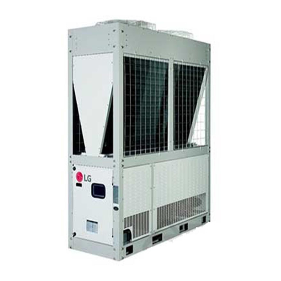
Air-cooled Inverter Scroll Chiller
SVC MANUAL
MODEL : ACHH Series
CAUTION
Before Servicing the unit, read the safety precautions in SVC manual.
Only for authorized service personnel.
Copyright © 2018 LG Electronics Inc. All rights reserved. Only training and service purposes.
Advertisement
Table of Contents

Related Manuals for LG ACHH Series


Summary of Contents for LG ACHH Series
- Page 1 Air-cooled Inverter Scroll Chiller SVC MANUAL MODEL : ACHH Series CAUTION Before Servicing the unit, read the safety precautions in SVC manual. Only for authorized service personnel. Copyright © 2018 LG Electronics Inc. All rights reserved. Only training and service purposes.
-
Page 2: Table Of Contents
Air-cooled Inverter Scroll Chiller 1. Safety Precautions ................3 2. Specification ..................8 3. Functions ....................9 4. Piping Diagrams ................10 5. Wiring Diagrams................13 6. Exploded View ..................22 7. The phenomena from main component failure ......34 8. Error code check ................55 9. Additional functions...............106 - 2 -... -
Page 3: Safety Precautions
Safety Precautions 1. Safety Precautions To prevent injury to the user or other people and property damage, the following instructions must be followed. n Incorrect operation due to ignoring instruction will cause harm or damage. The seriousness is classified by the following indications. WARNING This symbol indicates the possibility of death or serious injury. - Page 4 Safety Precautions There must be no obstruction above the unit. When transporting the product, use the forklift or spreader bar in accordance with the manual. - It would deflect discharge air downward where it could be re-cir- - Arbitrarily moving the product can cause product damage or culated back to the inlet of the condenser coil.
- Page 5 Safety Precautions Be careful during valve checkout about hot gas line Electric shock hazard. Can cause severe injury or death. Even when power to the panel is off, output board could be connected to high voltage. - It may become hot enough to cause injury. - Electric shock hazard.
- Page 6 Safety Precautions n Operation Do not use the Product in special environments. Make the connections securely so that the outside force of the cable may not be applied to the terminals. - Oil, steam, sulfuric smoke, etc. can significantly reduce the per- - Inadequate connection and fastening may generate heat and formance of the Product or damage its parts.
- Page 7 Specification 2. Specification Model ACHH020LBAB ACHH023LBAB ACHH033LBAB ACHH040LBAB Inverter Scroll Chiller Power Phase,Lines,V 3,4,380~415 3,4,380~415 3,4,380~415 3,4,380~415 65.0 74.0 114.0 130.0 Cooling 18.5 21.0 32.4 37.0 Capacity 70.3 82.0 120.0 140.6 Heating Input Cooling 22.2 27.4 36.8 44.4 Power Heating 21.6 27.3 35.3...
-
Page 8: Specification
Specification Model ACHH045LBAB ACHH050LBAB ACHH060LBAB ACHH067LBAB Inverter Scroll Chiller Power Phase,Lines,V 3,4,380~415 3,4,380~415 3,4,380~415 3,4,380~415 148.0 171.0 195.0 222.0 Cooling 42.1 48.6 55.4 63.1 Capacity 164.0 180.0 210.9 246.0 Heating Input Cooling 54.8 55.2 66.6 82.2 Power Heating 54.7 52.9 64.9 82.0 Max operating Current... -
Page 9: Functions
Functions 3. Functions Classification Function Single High pressure sensor Low pressure sensor Over current protection equipment Discharge overheat temperature control Reliability Between phase protection equipment 3 minutes delayed operation Freezing prevention Compression ratio limit Self diagnosis Automatic Re-start Remote control Convenience Low noise operation at night Automatic operation... -
Page 10: Piping Diagrams
Piping Diagrams 4. Piping Diagrams • 1 UNIT Cooling Heating Fan motor 4 way valve Pressure sensor Pressure switch Temperature sensor Solenoid valve Check valve Compressor Strainer Electonic expantion Valve Expansion valve - 10 -... - Page 11 Piping Diagrams • 2 UNIT Cooling Heating Fan motor 4 way valve Pressure sensor Pressure switch Temperature sensor Compressor Solenoid valve Check valve Strainer Electonic expantion Valve Expansion valve Compressor - 11 -...
- Page 12 Piping Diagrams • 3 UNIT Cooling Heating Fan motor 4 way valve Pressure sensor Compressor Pressure switch Temperature sensor Solenoid valve Check valve Strainer Electonic expantion Valve Expansion valve Compressor Compressor - 12 -...
-
Page 13: Wiring Diagrams
Wiring Diagrams 5. Wiring Diagrams • 1 UNIT, 2 UNIT (Main), 3 UNIT (Main) - 13 -... - Page 14 Wiring Diagrams • 2 UNIT (Sub), 3 UNIT (Sub2) - 14 -...
- Page 15 Wiring Diagrams • 3 UNIT (Sub1) - 15 -...
- Page 16 Wiring Diagrams • Chiller Main PCB UI1_G UI15_G (Ambient Temp.) (Load Flow Switch Input) CH4 A+ B- UI16_G (Modbus Communication Connector) (Load Pump Interlock Contact Input) CH3 A+ B- GRD_DI1 (HMI Communication Connector) (Remote On/OFF) GRD_DI2 CH2 A+ B- (Remote CO/Hp) (Communication Connector) GRD_DI3 12VDC+-...
- Page 17 Wiring Diagrams • ADAPTER - 17 -...
- Page 18 Wiring Diagrams • Cycle Main PCB - 18 -...
- Page 19 Wiring Diagrams • Cycle External PCB - 19 -...
- Page 20 Wiring Diagrams • Noise Filter PCB CN_IN_R CN_INV_R CN_IN_S CN_INV_S CN_IN_T CN_INV_T CN_IN_N • Inverter PCB - 20 -...
- Page 21 Wiring Diagrams • Fan PCB - 21 -...
-
Page 22: Exploded View
Exploded View 6. Exploded View 6.1 Fan Assembly 435512 559010 546810 149980 W4810A W4810B The parts are applied to 2UNIT and 3UNIT. - 22 -... - Page 23 Exploded View 6.2 Condenser Assembly W4811A 352114B 554030A 554030B W4810C 352114A W4811D W4811E 552115B W4811I W4811B W4811H W4811C W4811J 552115A W4811F W4811G The parts are applied to 2UNIT and 3UNIT. - 23 -...
- Page 24 Exploded View 6.3 Structure Parts W4811K 137213G 135312 137213B 137213D 137213H W49810B 137213D W49810C The parts are applied to 2UNIT. 137213I W49810C 137213D 137213A The parts are W49810A applied to 3UNIT. 137213C 137213F 137213E - 24 -...
- Page 25 Exploded View 6.4 Cycle Parts • H/P Model 352111B 552114C 352111A 552117B 552117A 55211GB 340090A 552114A 554160 552114B 548490 752111A 55211GA 553000A The parts are applied to 2UNIT. (Compressor2 Sump Heater) W4986A 553000B (Compressor1 Sump Heater) 340090B 752111B W4986B The parts are The parts are applied to 2UNIT and 3UNIT.
- Page 26 Exploded View • H/P Model 552114B 552114C 661400C 661400A 165010D 552204A 165010A 266010 552204A 165010B 266010 552202 661400B 552202 561410A 165010C 55211GA 55211GB 552200 561410B 661400H 52204C 552204C 661400G 661400F 661400E 552204B 552204B 661400D 552200 552209A 552209B Product name Location No. Positon Housing Color Switch Assembly.Pressure...
- Page 27 Exploded View 6.5 Base Structure, Control Box Structure 1 Unit 649950A 137210 Product name Location No. Position Housing color Thermistor Assembly,NTC 263230A Water Pipe Inlet+Outlet Blue Thermistor Assembly,NTC 263230B Comp1 Discharge+Liquid pipe +Suction pipe Green Thermistor Assembly,NTC 263230C Comp2 Discharge+Liquid pipe +Suction pipe Yellow Thermistor Assembly,NTC 263230D...
- Page 28 Exploded View 2 Unit 649950B 137213J 649950A 137210 Product name Location No. Position Housing color Thermistor Assembly,NTC 263230A Water Pipe Inlet+Outlet Blue Thermistor Assembly,NTC 263230B Comp1 Discharge+Liquid pipe +Suction pipe Green Thermistor Assembly,NTC 263230C Comp2 Discharge+Liquid pipe +Suction pipe Yellow Thermistor Assembly,NTC 263230D Comp1 Hex+SC Out + SC In...
- Page 29 Exploded View 3 Unit 649950C 137213J 649950B 137213J 649950A 137210 Product name Location No. Position Housing color Thermistor Assembly,NTC 263230A Water Pipe Inlet+Outlet Blue Thermistor Assembly,NTC 263230B Comp1 Discharge+Liquid pipe +Suction pipe Green Thermistor Assembly,NTC 263230C Comp2 Discharge+Liquid pipe +Suction pipe Yellow Thermistor Assembly,NTC 263230D...
- Page 30 Exploded View 6.6 Control Box Parts W6200 247810B 268711C 261704 268711A 268711B 247810A 268711D 268711E 346810 Product name Location No. Position Remarks 268711A Main PCB 268711B External PCB 268711C Adapter PCB 268711D Fan PCB 268711E Inverter PCB - 30 -...
- Page 31 Exploded View • SVC Product List Product No. Product No. Product No. Remarks Location No. Product Name 1UNIT 2UNIT 3UNIT Fan Assembly 435512 Cover Assembly, Top(Outdoor) ACQ34885913 ACQ34885913 ACQ34885913 559010 Fan Assembly, Propeller ADP73533501 ADP73533501 ADP73533501 546810 Motor Assembly,DC,Outdoor EAU43080023 EAU43080023 EAU43080023 149980...
- Page 32 Exploded View • SVC Product List Product No. Product No. Product No. Location No. Product Name Remarks 1UNIT 2UNIT 3UNIT Cycle Parts(H/P) 548490 Accumulator 4848A20001N 4848A20001N 4848A20001N 554160 Compressor Set,Korea TBZ37957001 TBZ37957001 TBZ37957001 Inverter Comp 552114A Tube Assembly,Discharge(Outdoor) AJR76182501 AJR76182501 AJR76182501 Oil Seperator 552114B...
- Page 33 Exploded View • SVC Product List Product No. Product No. Product No. Remarks Location No. Product Name 1UNIT 2UNIT 3UNIT Base Structure, Control Box Structure 649950A Case Assembly,Control(Outdoor) ABQ76280501 ABQ76280501 ABQ76280501 C/Box 649950B Case Assembly,Control(Outdoor) ABQ76280502 ABQ76280502 C/Box 649950C Case Assembly,Control(Outdoor) ABQ76280503 C/Box 137210...
-
Page 34: The Phenomena From Main Component Failure
The phenomena from main component failure 7. The phenomena from main component failure The phenomena from main component failure Component Phenomenon Cause Check method and Trouble shooting Not operating Motor insulation broken Check resistance between terminals and chassis Strainer clogged Change strainer Compressor Oil leakage... - Page 35 The phenomena from main component failure Brown White ø1 ø3 Orange Blue ø2 ø4 Orange Yellow Brown Blue Yellow • Pulse signal output value and valve operation Output state Output(ø) No. ø1 ø2 ø3 ø4 • Output pulse sequence - In valve close state: 4 ’ 3 ’ 2 ’ 1 ’ 4 - In valve open state: 1 ’...
- Page 36 The phenomena from main component failure CAUTION • Please process the failure with accordance to the correspond EEV as specified on the right of a table below. Failure mode Judgment method Failure process If EEV mechanical part is locked, a driving motor rotates and makes EEV mechanical part some little noises as load is not applied.
- Page 37 The phenomena from main component failure n EEV coil removal method of an Sub cooling circuit Sub cooling EEV is composed as a figure below and can be separated into a coil and a body. Body Lead Coil n Coil removal method Please hold the bottom part of a body tightly to not to be moved and take the coil out upwards.
- Page 38 The phenomena from main component failure n 3 Phase bridge diode inspection method Internal circuit diagram Appearance 1. Wait until Comp PCB DC voltage gets discharged, after the main power switch off (10 min). 2. Pull out all the connector connected with Inverter PCB. 3.
- Page 39 The phenomena from main component failure n Inverter IPM inspection method 1. Wait until the Inverter PCB DC voltage is discharged after main power off. (10 min.) 2. Pull out all the connector connected with Inverter PCB. 3. Set multi tester to resistance mode. 4.
- Page 40 The phenomena from main component failure n Fan IPM inspection method 1. Wait until the Fan PCB DC voltage gets discharged after the main power off. (10 min.) 2. Pull out the DC connector and U,V,W Fan connector connected with Fan PCB. 3.
- Page 41 The phenomena from main component failure n Pressure Sensor(High/Low Pressure Sensor) Connect manifold gauge to the service valve of outdoor unit, and compare the output of high pressure sensor to the output of low pressure sensor to detect the defect. below) Compare the output of pressure sensor to the output of manifold gauge pressure using the table below.
- Page 42 The phenomena from main component failure n Temperature Sensor 1) outdoor temperature sensor : TH1 2) Suction pipe(S-pipe) temperature sensor : TH2 3) Discharge pipe(D-pipe) temperature sensor : TH3 4) Outdoor heat exchanger (center of condenser) temperature sensor :TH2 1. Check the condition of installation and the contact of temperature sensor. 2.
- Page 43 The phenomena from main component failure n Inverter compressor M chiller is composed of 2 inverter scroll compressors. If occurring an error regarding a compressor and power while operating, please check and confirm following an order below. Items to be confirmed Symptom Treatment 1) When supplying for 12...
- Page 44 The phenomena from main component failure n Fan Motor Checking Item Symptom Countermeasure (1) The fan motor does not 1) When power supply is * Modify connection status in front of or at the rear of operate. abnormal the breaker, or if the power terminal console is at Does failure appears frosting condition.
- Page 45 The phenomena from main component failure n Compressor Compressor specification applying M chiller is as following as below. When there is a problem in a compressor, please check by referring to the compressor specification. Model name JQC068MAA Compony Form Inverter scroll Compression volume (cm3/rev) 62.1 Refrigerating machine oil...
- Page 46 The phenomena from main component failure Alarm An explanation regarding a failure is as following below CH x This displays the alarm code This displays the alarm cycle number. (0-3) 0: Common alarm 1: Alarm of cycle 1 2: Alarm of cycle 2 3: Alarm of cycle 3 This displays the unit number and current product is fixed to 1.
- Page 47 The phenomena from main component failure Failure name Failure code Occurrence condition Control when occurring Removal condition Load water flow switch error During a mobile and an operation, in case of detecting the turning off of load flow switch for 3 seconds, 3 CHxx013 times of accumulation occurs within a hour.
- Page 48 The phenomena from main component failure Failure name Failure code Occurrence condition Control when occurring Removal condition Inverter DC link high voltage error CHxx028 Defect from DC voltage and over-charge Stop applicable cycle Automatically return to normal condition Inverter compressor over current CHxx029 CT value excess Correspond cycle stop...
- Page 49 The phenomena from main component failure Failure name Failure code Occurrence condition Control when occurring Removal condition Low pressure sensor error CHxx042 Low pressure sensor is short/open Stop applicable cycle Automatically return to normal condition High pressure sensor error CHxx043 High pressure sensor is short/open Stop applicable cycle Automatically return to normal condition...
- Page 50 The phenomena from main component failure Failure name Failure code Occurrence condition Control when occurring Removal condition Communication error Communication defect occurrence CHxx052 Correspond cycle stop Automatic return to a normal condition Communication failure between Indoor and Outdoor Unit CHxx053 Communication failure between Indoor and Outdoor Unit Stop applicable cycle Automatically return to normal condition...
- Page 51 The phenomena from main component failure Failure name Failure code Occurrence condition Control when occurring Removal condition Fan CT sensor error CHxx075 Fan CT sensor is short/open Stop applicable cycle Automatically return to normal condition Fan over-voltage error CHxx077 Fan over-voltage Stop applicable cycle Automatically return to normal condition Fan start failure error...
- Page 52 The phenomena from main component failure Failure name Failure code Occurrence condition Control when occurring Removal condition Individual Inletwater temperature sensor error CHxx090 Individual Inletwater temperature sensor is short/open Stop applicable cycle Automatically return to normal condition Individual Outletwater temperature sensor error CHxx091 Individual Outletwater temperature sensor is short/open Stop applicable cycle...
- Page 53 The phenomena from main component failure Failure name Failure code Occurrence condition Control when occurring Removal condition Liquid pipe temperature sensor error CHxx113 Liquid temperature sensor is short/open Stop applicable cycle Automatically return to normal condition Sub cooling Suction temperature sensor error CHxx114 Sub cooling Suction temperature sensor is short/open Stop applicable cycle...
- Page 54 The phenomena from main component failure Failure name Failure code Occurrence condition Control during error Cancel condition Surge in fan board heat emitting plate temperature CHxx193 Surge in fan board heat sink temperature Stop applicable cycle Automatically return to normal condition Fan board heat emitting plate temperature sensor error CHxx194 Fan board heat emitting plate temperature sensor is short/open...
-
Page 55: Error Code Check
Error code check 8. Error code check Error number Errors Meaning Main cause of occurrence 1. Sensor connector~ Chiller board Temperature sensor contact defect Air temperature sensor error Open/Short 2. Chiller board defect 3. Sensor defect (Main cause) n Failure diagnosis method Is a sensor normally Insert a sensor connector connected to Chiller board ? - Page 56 Error code check Error number Errors Meaning Main cause of occurrence 1. Communication polarity connection In case where the communication defect HMI communication error between HMI and a chiller board is not 2. Address setting non-agreed performed for 30 second 3.
- Page 57 Error code check Error number Errors Meaning Main cause of occurrence 1. In case where a communication line is not connected In case where a cycle PBC 2. In case where a communication line is disconnected Communication error signal is not received at a 3.
- Page 58 Error code check Error number Errors Meaning Main cause of occurrence In case where a communication is not - Communication line polarity defect performed for 30 seconds after occur- - External communication equipment Remote communication error ring the first communication between a power abnormality chiller board and external communica- - Chiller PCB defect...
- Page 59 Error code check Error number Errors Meaning Main cause of occurrence - Contact defect of a contact point When the pump contact input is off for 3 sec- - External pump defect onds when starting or during operation and Load water pump inter- - Connection defect this condition occurs 3 times within one hour, locking error...
- Page 60 Error code check Error number Errors Meaning Main cause of occurrence - Contact defect of a contact point When the flow switch is off for 3 seconds when - Flow switch defect Load water flow switch starting or during operation and this condition - Connection defect error occurs 3 times within one hour, or flow switch...
- Page 61 Error code check Error Error Type Error Point Main Reasons 1.Over current detection at Inverter compres- sor(U,V,W) 2.Compressor damaged (insulation dam- IPM self protection circuit aged/Motor damaged) activation 3.IPM overheating Inverter PCB Assy. IGBT (Heat sink disassembled) Fault occur (Overcurrent/IPM overheat- 4.Inverter compressor terminal disconnected ing/Vcc low voltage) or loose...
- Page 62 Error code check * Measuring resistance between each terminal of compressor * Compressor wire connector connection point • IPM(IGBT) joining point • Check joining condition • Check DC Link connector joining condition - 62 -...
- Page 63 Error code check Error Error Type Error Point Main Reasons 1. Overload operation (Pipe clogging/Covering/EEV defect/Ref. overcharge) Inverter PCB Assembly 2. Compressor damage(Insulation input 3 phase power AC Input Current Over Error damage/Motor damage) current is over limited 3. Input voltage low value(24 A) 4.
- Page 64 Error code check * Measuring resistance between * Measuring input voltage each terminal of compressor R(L1) S(L2) T(L3) * Compressor wire connector connection - 64 -...
- Page 65 Error code check Error Error Type Error Point Main Reasons 1. DC Link terminal misconnection/terminal contact fault 2. Starting relay damage Inverter compressor DC Input voltage is over limited Link high voltage/ low volt- value of the product (300 V 3.
- Page 66 Error code check Error Error Type Error Point Main Reasons 1. Defective high pressure switch 2. Defective fan of indoor unit or outdoor unit 3. Check valve of compressor clogged 4. Pipe distortion due to the pipe damage 5. Refrigerant overcharge Excessive rise of discharge Compressor off due to the 6.
- Page 67 Error code check Error Error Type Error Point Main Reasons Input voltage is over limited 1. Input voltage abnormal (R-S-T) Input Voltage high/low value of the product (304 V 2. Outdoor unit inverter PCB assembly dam- (251) or less, 536 V or more) age (input voltage sensing part) n Error Diagnosis and Countermeasure Flow Chart Are there any power wire...
- Page 68 Error code check Error Error Type Error Point Main Reasons 1. Overload operation (Pipe clogging/Covering/EEV defect/Ref. overcharge) Inverter compressor starting Starting failure because of 2. Compressor damage (261) failure Error compressor abnormality (Insulation damage/Motor damage) 3. Compressor wiring fault 4. ODU inverter PCB damage (CT) n Error Diagnosis and Countermeasure Flow Chart 1.
- Page 69 Error code check Error Error Type Error Point Main Reasons 1. Overload operation (Pipe clogging/Covering/EEV defect/Ref. overcharge) Inverter compressor over Inverter compressor input 2. Compressor damage(Insulation (291) current current is over 30 A damage/Motor damage) 3. Input voltage low 4. ODU inverter PCB assembly damage n Error Diagnosis and Countermeasure Flow Chart 1.
- Page 70 Error code check Error number Errors Meaning Main cause of occurrence Inverter compres- 1. Inverter compressor 1, 2 discharge pipe temperature Compressor off caused by sor 1, 2 discharge sensor defect an excessive increase of an temperature 2. Refrigerant shortage/ Leakage (321) Inverter compressor 1, 2 excessive...
- Page 71 Error code check Error number Errors Meaning Main cause of occurrence 1. High voltage sensor failure 2. Fan failure 3. Deformation caused by refrigerant pipe damage Compressor dis- Error caused by a continu- 4. Refrigerant over charge charge pressure ous occurrence of compres- 5.
- Page 72 Error code check Error number Errors Meaning Main cause of occurrence 1. Defective low pressure sensor 2. Defective outdoor/indoor unit fan 3. Refrigerant shortage/leakage Error happens because of 3 4. Deformation because of damage of refrigerant pipe Excessive drop of times successive compres- 5.
- Page 73 Error code check Error Error Type Error Point Main Reasons Micom input voltage isn't 1. Input voltage abnormal (R-S-T) Inverter compressor CT within 2.5 V ±0.3 V at ini- 2. ODU inverter PCB damage (401) sensor error tial state of power supply (CT sensing part) n Error Diagnosis and Countermeasure Flow Chart 1.
- Page 74 Error code check Error number Errors Meaning Main cause of occurrence 1. Compressor discharge pipe temperature sensor Inverter compressor Resistance measurement connector connection defect discharge pipe tempera- value of a sensor is 2. Compressor discharge pipe temperature sensor (411) ture sensor error abnormal (Open/Short) defect (Open/Short) 3.
- Page 75 Error code check Error number Errors Meaning Main cause of occurrence 1. Bad connection of low pressure connector Sensor error of Abnormal value of sensor 2. Defect of low pressure connector (Open/Short) (421) low pressure (Open/Short) 3. Defect of outdoor PCB 1.
- Page 76 Error code check Error number Errors Meaning Main cause of occurrence Heat exchanger Resistance measurement 1. Temperature sensor connector connection defect pipe temperature value of a sensor is abnor- 2. Temperature sensor defect (Open/Short) (451) sensor error mal (Open/Short) 3. PCB defect Compressor suc- Resistance measurement 1.
- Page 77 Error code check Error Error Type Error Point Main Reasons 1. Input Voltage abnormal (R,S,T,N) ODU 3phase power omis- Omitting one or more of 2. Check power Line connection condition R,S,T input power sion error 3. CYCLE Main PCB damage (501) 4.
- Page 78 Error code check Error Error Type Error Point Main Reasons 1. Power cable or communication cable is not Communication error connected Main controller of Master between unit can’t receive signal 2. Defect of outdoor Main fuse/Noise Filter (Inverter PCB ‘ CYCLE (521) from inverter controller 3.
- Page 79 Error code check Error number Errors Meaning Main cause of occurrence 1. Communication cable is not connected When the indoor unit Communication error 2. Disconnection or short circuit of the communication line signal is not received (indoor unit → main 3.
- Page 80 Error code check Error number Errors Meaning Main cause of occurrence 1. Bad Connection Between Inv and Main Communication error : Failing to receive 2. Communication Wire Noise Effect CYCLE Main PCB ÷ inverter signal at main (571) 3. CYCLE Main PCB Damage Inverter PCB PCB of Outdoor Unit 4.
- Page 81 Error code check Error No. Error Type Error Point Main Reasons 1. EEPROM contact defect/wrong insertion EEPROM Access error Inverter PCB EEP- 2. Different EEPROM Version and Check SUM error (601) ROM error 3. ODU inverter PCB assembly damage n Error Diagnosis and Countermeasure Flow Chart 1.Check EEPROM insert direction/connection condition 2.Check EEPROM Check SUM Is EEPROM insertion normal?
- Page 82 Error code check Error number Errors Meaning Main cause of occurrence 1. Cooling fan locking status defect Excessive temperature If the temperature 2. Inverter board power module locking status defect rise at the inverter detected at the heat 3. Outdoor unit plate motor abnormal operation board heat radiation radiation plate is 90 °C 4.
- Page 83 Error code check Error number Errors Meaning Main cause of occurrence Abnormal sensor 1. Bad connection of low pressure connector Inverter power modul resistance value 2. Defect of low pressure connector (Open/Short) sensor error (Open/Short) 3. Defect of outdoor PCB n Failure diagnosis method Is a sensor normally Insert a sensor to PCB...
- Page 84 1. Check resistance between each phase(U,V,W) of fan motor terminal -Panasonic Motor : 9.5 Ω ± 5 % (@25 ℃) -LG Motor : 8.6 Ω ± 7 % (@25 ℃) Is ODU Fan Motor normal? 2. Check insulation resistance between fan motor terminal(U,V,W) →...
- Page 85 Error code check Error number Errors Meaning Main cause of occurrence In case where micom 1. Input voltage 15 V abnormality Fan CT sensor input voltage of the top 2. Power wire disconnection and connector contact defect (751) defect current at the fan motor is 3.
- Page 86 Error code check Error number Errors Meaning Main cause of occurrence 1. Overload operation 2. Fan motor defect Fan over voltage In case where output cur- 3. Fan board defect (771) error rent is flow more than 5A 4. Fan motor connector insertion defect 5.
- Page 87 Error code check Error No. Error Type Error Point Main Reasons 1.Fan motor defect/ assemble condition abnor- Fan Starting Failure Fan Motor initial starting failure 2.Fan motor connector misconnection (791) Error (Hall sensor, U,V,W ouput) 3.Fan PCB defect n Error Diagnosis and Countermeasure Flow Chart Is fan motor assemble Check ODU fan motor assemble condition and locking condition normal?
- Page 88 Error code check Error number Errors Meaning Main cause of occurrence CYCLE Main PCB 1. No EEPROM EEPROM Access Error (861) EEPROM Error 2. EEPROM wrong insertion n Failure diagnosis method Is EEPROM assemble Reset after checking EEPROM assemble condition condition normal? Replace Correct EEPROM Correct check sum...
- Page 89 Error code check Error No. Error Type Error Point Main Reasons 1.EEPROM bad contact/wrong insertion Error occurs when checking the Fan PCB EEPROM EEPROM checksum as initializing 2.EEPROM Version is different (871) Error after power is supplied 3.ODU fan PCB assembly damage n Error Diagnosis and Countermeasure Flow Chart 1.
- Page 90 Error code check Error number Errors Meaning Main cause of occurrence Communication Fan controller didn't 1. Wrong connection between Inverter and Fan PCB error (Fan PCB ÷ receive signal from invert- 2. Fan PCB power not supplied (11 → 051) Inverter PCB) er controller 3.
- Page 91 Error code check Error number Errors Meaning Main cause of occurrence 1. Overload operation (Pipe clogging/Covering/EEV defect/Ref. overcharge IPM protection circuit acti- Fan PCB IPM 2. Fan motor assemble condition abnormal (Coil disconnec- vation (over current / over- (11 → 061) Fault tion/Short/Insulation damage) heating)
- Page 92 Error code check Error number Errors Meaning Main cause of occurrence 1. Connection defect between an inverter board and a fan board In case where DC Link 2. Fan board defect [DC Link detection part] Fan DC Link low voltage of a fan board is 3.
- Page 93 Error code check Error number Errors Meaning Main cause of occurrence Outdoor unit liquid 1. Defective temperature sensor connection pipe (condenser) Abnormal sensor resis- 2. Defective temperature sensor (Open / Short) (11 → 113) temperature sen- tance value (Open/Short) 3. Defective outdoor unit PCB sor error Error number Errors...
- Page 94 Error code check Error number Errors Meaning Main cause of occurrence Communication When external signal is defect (main not received at the main 1. Power cable / Communication cable is not connected. board, external board due to the disorder 2. Outdoor unit main / external board defect board) of the external board n How to diagnose the disorder...
- Page 95 Error code check Error number Errors Meaning Main cause of occurrence 1. 4way valve malfunction by entrance of foreign object 2. No high pressure/low pressure difference generated due Outdoor unit 4 way Outdoor unit 4 way valve to damage of the compressor valve switching (11 →...
- Page 96 Error code check 4way valve connector location in main PCB (Note 1) Measure resistance to see if 4way valve is normal (It is marked as CN16_VI, CN25_BK) *Normal value: several kΩ (Note 2) Check if the coil is fully inserted in 4way valve. (Note 3) During the heating operation, check if 220V is output from PCB - 96 -...
- Page 97 Error code check Error number Errors Meaning Main cause of occurrence Fan board radiator con- In case where radiator 1. Radiator temperature sensor abnormality nection temperature detection temperature is 2. Temperature sensor connector connection defect (11→931) excessive increase more than 95 ℃ 3.
- Page 98 Error code check n Inverter compressor and static speed compressor When replacing a compressor, please follow the procedure to replace • Before replacing a compressor, please judge if it is an inverter compressor failure or a static speed compressor failure and then replace.
- Page 99 Error code check Compressor Check start After the starting, is there a difference between high pressure and low pressure? Terminal reconnection or Is 3 Phase power connected power supply to the correct direction? direction replacement PCB replacement Is a signal normally permitted from PCB? When operating a compressor, is current valve normal? Are all the directions of...
- Page 100 Error code check Check start When permitting power initially, Is power normally supplied is there an initialization vibration? to outdoor EEV? replacement When operating Check valve normally, is there a temperature Is a check valve normal? difference of the front and the rear replacement of cooling EEV? When operating...
- Page 101 Error code check Sub cooling EEV Check start When operating cooling, is there a temperature difference of the front and the rear of Sub cooling EEV? (In case of EEV open) Terminal Is PCB terminal connection normal? reconnection Is a signal normally permitted from PCB? PCB replacement EEV coil check and Sub cooling EEV When operating...
- Page 102 Error code check 4 Way Valve Start inspection After 3 minutes from the starting, is the difference of high pressure and low pressure 4 atmosphere or more? Solve the Does compressor operate normally? compressor problem Connect the Is PCB connector correctly connected? connector again Replace PCB Is voltage applied normally from PCB?
- Page 103 Error code check Inverter outdoor fan Check start Is a contact of IPM power Fan IPM board replacement part and signal part normal? Is a fan moved Is a fan moved when operating under 700 kPaG of when operating exceed 2 700 kPaG of heating low pressure? cooling high pressure? Fan motor replacement...
- Page 104 Error code check Temperature sensor Check start 1. Confirm a connector position and connection direction After permitting power, 2. Confirm whether or not having a contact is temperature value on LGMV normal defect before operation? PCB confirmation Is normal resistance output? and replacement No problem on a temperature sensor Temperature sensor replacement...
- Page 105 Error code check Pressure switch Check start Is a compressor Make a pressure switch short and then start an suddenly stop moving at the pressure operation which a pressure switch is not operated? Is it normally operated? No problem on a pressure switch PCB confirmation and replacement Pressure switch replacement CAUTION...
-
Page 106: Additional Functions
9. Additional functions 9. Additional functions Vacuum mode If you need vacuum after service at the product installation site, when you set vacuum mode func- tion, all valves and EEV are open. 1. Turn on Cycle Main PCB Dip S/W No. 4. 2. - Page 107 January, 2018 P/NO : MFL67288419...