Table of Contents
Advertisement
Quick Links
INSTRUCTION MANUAL
Water-Cooled Turbo Chiller
Please read the safety precautions before use.
This content is to ensure the safety of users and to prevent property damages.
Keep the instruction manual in a place that is accessible to other users.
Only authorized people can use the product.
Model : RCWFH Series (200-3000RT)
(For AC Smart Premium Control System)
P/NO : MFL68929306 (Rev 0)
www.lge.com
Advertisement
Table of Contents

Related Manuals for LG RCWFH Series


Summary of Contents for LG RCWFH Series
- Page 1 This content is to ensure the safety of users and to prevent property damages. Keep the instruction manual in a place that is accessible to other users. Only authorized people can use the product. Model : RCWFH Series (200-3000RT) (For AC Smart Premium Control System) www.lge.com...
- Page 2 For your records Staple your receipt to this page in case you need it to prove the date of purchase or for warranty purposes. Write the model number and the serial number here: Model number : Serial number : You can find them on a label on the side of each unit. Dealer’s name : Date of purchase :...
-
Page 3: Cautions For Safety _ Warning/Caution
- Improper wiring or installation may cause fire or electric shock. • Do not disassemble, repair or reconfigure the unit. - LG Electronics is not responsible for the any damage or loss from the arbitrary disassembly, repair or reconfigura- tion of the unit. - Page 4 • Installing the product in small space requires separate measures to keep the leakage of the refrigerant within the safety limits in case of any leakage. - Consult the authorized dealer for appropriate measures to prevent the refrigerant leakage from exceeding the safety limits.
- Page 5 • Wear safety equipment - Wear safety glasses and work gloves. Be careful when installing or operating the chiller and operating the electri- cal components. • Always run fluid through heat exchangers when adding or removing refrigerant charge. - Potential damage of the tube within the heat exchanger can be prevented. Use Appropriate brine solution in cooler fluid loops to prevent the freezing of heat exchangers when equipment is exposed to temperature below 0°C.
-
Page 6: Caution
1-2. CAUTION Operation & Maintenance • Always check for gas(refrigerant) leakage after installation or repair of product. - Low refrigerant levels may cause failure of product. • Do not install the unit where combustible gas may leak. - There is risk of fire or failure of product •... - Page 7 - This make it possible to ensure proper machine performance and reduce the potential of tubing damage due to corrosion, scaling, erosion and algae. LG Electronics is not responsible for any damage caused by cooling water not treated or improperly treated.
- Page 8 • Do not operate with wet hand. - It may cause electric shock. • During maintenance work, check whether all of the power lines connected to the control panel or starter panel are interrupted. - It may cause electric shock. •...
-
Page 9: Table Of Contents
Thank you for using the Water-Cooled Turbo Chiller. You may use the product more conveniently and safely by installing the product following the standard after reading the instruction manual. • Make sure to read the instruction manual to install the Turbo Chiller safely and correctly before use. •... -
Page 10: Introduction
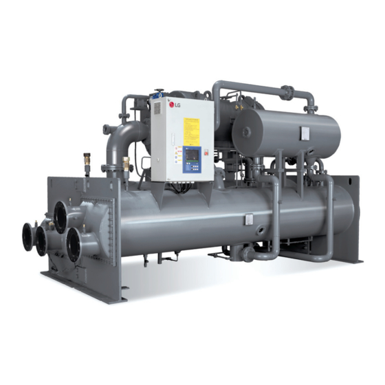
2. INTRODUCTION 2-1. General Information This manual describes the installation of water cooled screw type two stage centrifugal chiller using R-134a refriger- ant and X30 controller applied. 2-2. System structure Fig. 1 shows the general structure and parts composition of two stage centrifugal chiller. The location of control panel, the shape of waterbox, direction of inlet and outlet of the chilled water and cooling water, and some of the pipes may vary by model or customer’s specifications. -
Page 11: Nomenclature
2-3. Nomenclature The nomenclature for the Fig. 2 centrifugal chiller is as follows. R : R134a W : Water-Cooled Compressor Code Condensor Code Cooling Only K : Water-Cooled Heating Pump R C W F H D 3 E A D E Code for Certifica- Evaporator C : CHILLER... -
Page 12: Main Unit Conversions
2-5. Main unit conversions Temperature conversion table (°F ↔ °C) • °F = (9/5 x °C) + 32 • °C = 5/9 x (°F - 32) °F °C °F °C °F °C °F °C °F °C -17.2 -0.6 16.1 32.8 49.4 -16.7 16.7... - Page 13 ↔ kg/cm Pressure conversion table (lb/in • lb/in = psi ex) 1 lb/in = 0.07030696 kg/cm lb/in kg/cm lb/in kg/cm lb/in kg/cm lb/in kg/cm lb/in kg/cm 5.695 0.070 2.883 8.507 11.32 5.765 0.141 2.953 8.577 11.39 5.836 0.211 3.023 8.648 11.46 5.906 0.281...
-
Page 14: Structure Of Two Stage Centrifugal Chiller
3. STRUCTURE OF TWO STAGE CENTRIFUGAL CHILLER 3-1. Cycle of the chiller The two Stage Centrifugal chiller uses environment friendly high pressure refrigerant R-134a. - In this cycle, as shown in the following figure, the vaporized low temperature and low pressure refrigerant gas passes the Inlet Guide Vane, and enters the 1st impeller of the compressor. -
Page 15: Main Components Of The Two Stage Centrifugal Chiller
3-2. Main components of the two stage centrifugal chiller Compressor 1) Hermetic Motor with Refrigerant Cooling Method 2) Open type Impeller 3) Diffuser 4) High speed gear device (Helical gear type) 5) Thrust Bearing Fig 5. Hermetic two-stage high-speed compressor *Two-stage centrifugal chiller compressor is composed of impeller, bearing, diffuser, capacity control device and high-speed gear. - Page 16 Heat exchanger Heat exchanger of two-stage centrifugal chiller is composed of two shell type for easy separation into evaporator and condenser. The tubes are arranged so as to maximize the heat exchanging ability. It is also designed so that the re- frigerant can be spread evenly on all tubes for the sake of surge prevention and the COP decrease in part load opera- tion.
- Page 17 Lubrication system Bearing Oil inlet Oil tank Oil outlet Oil outlet sight glass Oil cooler Oil filter Oil inlet Figure 9. Lubrication cycle Introduction The discharged lubricating oil by the oil pump enters the oil filter to get rid of any unnecessary foreign substance. This oil becomes cooled to the temperature appropriate for operation condition after through the oil cooler, part of it directly enters gear and high speed side bearings, and the remainder directly enters motor shaft bearings.
- Page 18 Oil reclaim system Oil reclaim system provides the system to reclaim the oil from the heat exchanger and let it come back to the oil tank. Normally, it is reclaimed at the evaporator, and the vane housing. Refrigerant which came back into the oil tank will then be evaporated to the gas and flow through the Oil Seperator line which is located at the upper part of the casing, and then it will be sent to the inlet of the compressor.
- Page 19 Safety devices For the sake of safe operation and the protection of the chiller, safety devices are ready as the next table. Installation Quan- No. Safety Devices Measurement Item Description Location tity Chilled Water Chiller stops operation if the chilled water outlet Chilled water Chilled water inlet Temperature...
- Page 20 Installation Quan- Item Measurement Item Description Location tity To prevent the accident by unexpected fire, and so on which can cause pressure increase in the chiller, the relief valve will be operated and ex- Evaporator & haust the refrigerant into the air if the pressure Relief Valve condenser Relief valves...
-
Page 21: Control System
4. CONTROL SYSTEM 4-1. Components and Major Parts of the Control Panel FRONT BACK BOTTOM Figure 10. HMI Components Item Description • 10.2 inch LCD control panel ① Touch screen • AC Smart Premium control and display various information ② SD memory slot (for services) SD card memory slot for S/W upgrades ③... - Page 22 MASTER/SLAVE The Master board and Slave board has the same hardware. They are used as Master or Slave by DIP switch settings. (SW4 OFF : Master, ON : Slave) Analog input/output and digital input/output consist of RS232 and RS485 communication connectors for the user’s convenience.
- Page 23 Control System Block Diagram The Master, Slave, HMI and Relay boards communicate in the RS485 communication method, and one Master/Slave board consists of the analog input (12 channels for temperature, 10 channels for current), analog output (4 channels for current), digital input (20 channels) and digital output (16 channels). The Relay board is responsible for controlling the guide vane and diffuser vain.
- Page 24 Other control parts NOIS MASTER / FILTER TRANSFORMER FUSE SLAVE BOARD BREAKER RELAY BOARD RELAY MAGNETIC CONTACTOR SUMMER RELAY BUZZER TERMINAL BLOCK Fig 13 Control system. Figure 13. Control System h Please refer to the approved diagram for details as the arrangement shown above may vary by model and change for design improvements and the user’s convenience.
- Page 25 BACnet Converter Our controller basically supports Modbus communication protocol. If the higher communication protocol is BACnet, the protocol should be converted by applying a separate BACnet. A communication converter can only be attached inside the control board. Refer to the table shown below for meanings and explanations for each lamp. Figure 14.
- Page 26 FDS POWER FUSE BREAKER (TRANSFORMER FOR GAUGES) SERIES REACTOR (OPTION) PHASE ADVANCE CAPACITOR (OPTION) VACUUM CONTACTOR REACTOR (STARTER) MOMENTARY POWER FAILURE COMPENSATION DEVICE (OPTION) MOTOR PROTECTION RELAY Figure 15. 6600V Reactor Starter Method h Please refer to the approved diagram for details as the arrangement shown above may vary by model and change for design improvements and the user’s convenience.
-
Page 27: Control Parts Attached On The Product
4-3. Control Parts Attached on the Product Slave board Slave board Transformer Fuse Relay board Magnetic contactor & Thermal relay Breaker Display board Terminal block Master board Figure 16. Control Board 4-4. Basic Control Algorithm The algorithm managed to implement the best control by minimizing Under-shoot and Over-shoot when automati- cally/manually converting time to approach a goal, steady status error, initial operation and vane adjustment com- pared to the previous method by applying unique P (proportion), I (integration) and D (differentiation) algorithms to the cold water temperature control. -
Page 28: Bms Support Function
4-5. BMS Support Function The basic communication of the Turbo Chiller is Modbus protocol, and it is compatible with higher communication methods. Communication Protocol Support • Communication method - Standard: RS-485, Ethernet (option) • Protocol - Standard: MODBUS - Option: BACnet, TCP/IP 1 SET OF THE CONVERTER CAN BE Protocol CONNECTED UP TO 8 UNITS... -
Page 29: Power Panel And Interface Signal
4-7. Power Panel and Interface Signal Signal name Signal type Signal meaning Notes The interlock checks the op- Detect status of a contact eration of the electric con- by outputting DC24V. tactor for pump operation. Make sure to avoid resist- If there is no signal when Cold water pump interlock Input... -
Page 30: Start And Control Order
4-9. Start and Control Order Figure 20. Turbo Chiller Signal Flow Graph... - Page 31 Turbo Timing Sequence - Run Start button Start lamp Check cold water pump interlock alarm Check cold water pump interlock abnormality Cold water pump start/stop Check cold water flow alarm Check cold water flow abnormality Cold water pump interlock Cold water differential pressure switch Check coolant pump interlock alarm Check coolant pump interlock abnormality...
- Page 32 Turbo Timing Sequence - Stop Stop button Stop lamp Cold water pump start/stop Cold water pump interlock Cold water differential pressure switch Coolant pump start/stop Coolant pump interlock Coolant differential pressure switch Oil pump start/stop Based on the one that operates first among vane closed switches, soft stop settings or vane closed timer Compressor start/stop Operation complete...
-
Page 33: Product Protection Function
4-10. Product Protection Function Category Description Cause Action Status Sensor abnormality such as tem- Detected temperature, pressure The Chiller Abnormal Sensor perature, pressure and current, etc. and current sensor abnormality stops Cold water pump interlock abnor- Detected pump interlock abnormal- The Chiller Abnormal mality... - Page 34 Category Description Cause Action Status Oil temperature ≤ operation oil Display low oil temperature Block low oil run Caution Low temperature setting value block control caution message The guide closes the vane when a com- Display low voltage block con- Block low voltage pressor motor voltage goes below low Caution...
- Page 35 Category Description Cause Action Status High motor winding tem- Coil temperature input contact opens The Chiller stops Abnormal perature contact opens Low evaporator refrigerant Low evaporator refrigerant temperature temperature contact The Chiller stops Abnormal contact closes closes Thermal type overcurrent relay contact Oil pump overcurrent con- attached on the oil pump power line The Chiller stops...
-
Page 36: Checklists Before Inspection
4-11. Checklists before inspection 1) Thorough preparation Check emergency treatment method, cleanness of surroundings, and safety of facilities and machines. 2) Review based on the circuit diagram When the power system is supplied through other systems, check various power sources, if the 1st breaker is supplying the power or not and installation status of the ground wire. -
Page 37: Checklists After Inspection
4-12. Checklists after inspection 1) Final check list - Check if a worker is inside the site. - Check if demolishment of temporary buildings constructed for inspection is not delayed. - Check that bolts are tightened properly. - Check if tools, etc. are left. - Check if mice and insects, etc. -
Page 38: General Checklist
4-13. General Checklist Inspec- Inspection Inspection items Criteria tion categories Daily 1 year 2 years Is there any dust? Ambient Is the ambient temperature and humidity ade- Refer to Chapter 1. Environ- environ- quate? mental conditions ment Is there any abnormal vibration? Equipment Is there any vibration or noise? No abnormality Input volt-... -
Page 39: Hmi
5. HMI 5-1. Start HMI 1.1 Menu Structure START HOME SCHEDULE HISTORY VIEW ALL VIEW VIEW SCHEDULE HISTORY EVAPORATOR ADD/EDIT VIEW DETAILS CONDENSER SCHEDULE COMPRESSOR MANUAL CONTROL DEVICE ENVIRONMENT LOG IN SETTING SETTING USER GENERAL SETTING SYSTEM SCREEN SETTING REGISTER CUSTOMER SETTING A DEVICE NETWORK SETTING... - Page 40 1.3. How to LOGIN It is divided into LOGOUT/LOGIN (ADMINISTRATOR/INSTALLER). General users other than the administrator and installer cannot access major setup items by categorizing accessible areas for each authority. All setup items except operation stop can be accessed after login including operation start. LOG IN LOG IN Function...
- Page 41 1.4. Top Menu The top menu consists of date/time information, product information, control mode, temperature settings, operation status, warning message, operation mode and the operation control button. When messages for abnormality appear, the disable warning button feature is additionally provided on the right side of operation status and warning message area.
- Page 42 1.5. Bottom Menu The bottom menu consists of the main menu and the login button at the bottom of the screen. 1.Home 2. Schedule 3. History 4.Device setting 5. Environment 6.LOGIN setting Figure 25. Bottom Menu 1. Home Go to Home screen. 2.
-
Page 43: Home Screen Composition
5-2. Home Screen Composition 2.1. View All This consists of the main menu and LOGIN buttons at the bottom of the screen. Figure 26. View All Component Description Device name Provides device names. This tab provides overall information about the Chiller, and it is the default View all tab when accessing the home screen for the first time. - Page 44 2.2 Evaporator Displays DATA related to the animation screen of the evaporator. Figure 27. Evaporator Component Description Animation Provides the evaporator animation. Displays evaporator leaving water temperature and motor current. Provides Major information of the device same information when moving to other information tabs. Provides evaporator pump interlock/flow contact/outlet water setting tem- Main information perature information.
- Page 45 2.3. Compressor Display data related to the compressor animation display. Figure 28. Compressor Component Description Animation Provides the compressor animation. Displays evaporator leaving water temperature, inverter pressure and flow. Major information of the device Provides the same information when moving to other information tabs. Provides inverter frequency/one stage variable diffuser/two stage variable Main information diffuser/hot gas valve information.
- Page 46 2.4. Condenser Display DATA related to the condenser animation. Figure 29. Condenser Component Description Animation Provides the condenser animation. Displays evaporator leaving water temperature and motor current. Provides Major information of the device the same information when moving to other information tabs. Main information Provides condenser pump interlock/flow contact/pressure information.
- Page 47 2.5. Manual control Display DATA related to the condenser animation screen. Figure 30. Manual Control Component Description Displays a vane opening value and provides 0~100% control function when selecting manual/automatic setting and automatic by pressing the setting button. Vane opening Manual opening does not work when the product doesn’t operate since closing is enforced by circuit.
- Page 48 2.6. Home Screen Display Information Display menu Display item Display range Display unit Notes Displays evaporator leaving water temperature 3 digit and 1 decimal places (XXX.X) °C(°F) Displays motor current 4 digit and 1 decimal places (XXXX.X) Displays evaporator flow contact 3 digit and 1 decimal places (XXX.X) °C(°F) Displays evaporator entering water temperature...
- Page 49 Display menu Display item Display range Display unit Notes Compressor Displays bearing temperature 3 digit and 1 decimal places (XXX.X) °C(°F) Displays vibration 3 digit and 1 decimal places (XXX.X) mm/s Note 1 Displays power 4 digit places (XXXX) Note 1. Displays motor winding R temperature 3 digit and 1 decimal places (XXX.X) °C(°F)
-
Page 50: Schedule
5-3. Schedule The schedule is function for the device to implement desired actions at a specific time by appointing actions in ad- vance. The device can operate automatically only with the set schedules if the device is controlled at a fixed schedule. How- ever, the schedule control for starting the operation can be implemented only when the device is standby to imple- ment scheduled actions. - Page 51 3.2 Add/Edit Schedule Figure 32. Add/Edit Schedule Component Description Enter schedule name Enters schedule name after selecting Enter setting time Enters time to implement corresponding actions. Sets valid period for corresponding schedules. Set setting period *Default when adding schedules: today’s date . Set repeating pattern for schedules.
-
Page 52: History
5-4. History This function displays the history related to operation and errors of the Chiller. 4.1. View History (operation/ Error) Figure 33. History Component Description Provides all information whether it is an operation or error All category tab when selecting the all category tab. Provides list information corresponding to operation data Operation category tab when selecting the operation button. - Page 53 4.2 View details Figure 34. View Details Component Description Error code Displays error code Detailed information Displays error message information. Help Provides cause of error and help inspection and corrective actions. Table 18. View Details Items...
-
Page 54: Device Setting
5-5. Device Setting 5.1 User 5.1.1 Basic Setting This menu for users to set values needed for operation of the Chiller. Figure 35. Basic Setting 1) Select Control Mode - Local: This is to start/stop the Chiller by using the start/stop key on the control board of the controller at the site of installation. - Page 55 - Operation is available only when an inverter is attached on the user MCC(Motor Control Center) panel. This is an option, and this can be applied after a consultation with LG. - Control output of the cooling tower fan is available to have one of 4~20mA, 0~5Vdc or 0~10Vdc signals from the controller.
- Page 56 5) Motor Current Block This is to set motor and current control actions to protect the motor from overload. The current block action is implemented as shown below, and temperature control is not implemented when cur- rent block action is under operation. However, it is implemented in accordance with the P.I.D calculation value when P.I.D calculation value is smaller than the vane opening value while current control action is under operation.
- Page 57 6) Guide Vane Maximum This function is to protect the motor from overload or to block a load of the Chiller artificially. This blocks the guide vane from opening bigger than the setting. 7) Hot Gas (Vane %) This is an item to set when applying a hot gas bypass valve. Action to open a hot gas bypass valve is implemented when opening reaches the setting when closing the vane after reading feedback signals for controlling the opening of the guide vane.
- Page 58 Setting Setting Minimum Maximum Adjustment Item name Unit Notes Availability Value value Unit Select ● Control mode Local/Schedule/Remote a list Control Mode : Cool → Cool Control Mode : Cold Select ● Operation mode → Cool/Cold a list Control Mode : Heat →...
- Page 59 5.1.2 System Check Figure 40. System Check Setting avail- Minimum Maximum Adjustment Item name Setting UI Unit Notes ability value value Unit Monitoring Master (SW version) Monitoring Slave (SW version) Monitoring Master °C (PCB temper- ature) Monitoring Slave °C (PCB temper- ature) Table 20.
- Page 60 5.1.3 Check Input status Display ON (Closed circuit)/OFF (open circuit) of the digital input port. This menu is to check input signal ground stages connected to the control board of the Chiller. When inspecting the digital input, make sure to check the control circuit drawing so that other signals are not input to the input terminal of the controller.
- Page 61 5.1.3.2 Slave Figure 42. Input Status Check Slave Setting Item Name Contact Action Status Notes availability High bearing temperature contact When temperature is high: closed circuit ON/OFF High motor winding temperature contact When temperature is high: closed circuit ON/OFF Oil pump overload contact When there is overload: closed circuit ON/OFF Closed vane contact...
- Page 62 5.1.4 Check Output Status Display the status of ON (Closed circuit)/OFF (open circuit) of the digital output port and analog output. This menu is to display the output status by internal calculation in the controller, and is structured in the way that output results by controller calculations can be found.
- Page 63 5.1.4.2 Slave Figure 44. Output Status Check Slave Setting Item Name Contact Action Status Notes availability Oil heater run When heater operates: Closed circuit ON/OFF Oil pump run When pump operates: Closed circuit ON/OFF Buzzer When there is abnormality: Closed circuit ON/OFF Run status display When operating: Closed circuit...
- Page 64 5.1.5 Check Operation Hours Figure 45. Check Operation Hours Setting avail- Minimum Maximum Adjustment Item name Setting UI Unit Notes ability value value Unit Number of Chiller ● Rounds operation Hours of Chiller ● Hours operation Number of com- ● Rounds pressor operation Hours of compres-...
- Page 65 5.2 System 5.2.1 Control Information This is menu for the user to set values needed to operate the Chiller. Figure 46. Control Information Setting avail- Setting Minimum Maximum Adjustment Item name Unit Notes ability value value Unit Select ● Automatic restart Stop/Restart a list Select a...
- Page 66 5.2.2 Abnormality Condition This is menu to set values related to the abnormality of the Chiller. Figure 47. Abnormality Condition 1) Oil differential pressure Maximum This is to set the minimum oil differential pressure. The chiller stops due to abnormality if an oil differential pressure is below the setting when operating. 2) Low evaporator pressure This is to set the minimum evaporator pressure.
- Page 67 5.2.3 Safety Control This is to set values related to the safety control of the Chiller. Figure 48. Safety Control Setting Setting Minimum Maximum Adjustment Item name Unit Notes availability value value Unit Automatic Control Select ● Use/Not use Setting Value a list Surge High Select...
- Page 68 5.2.4 Timer This is to set values related the timer needed for operation of the Chiller. Figure 49. Timer Setting Setting Minimum Maximum Adjustment Item name Unit Notes availability value value Unit Evaporator Water Select ● Seconds 1800 Pump Stop a number Condenser Water Select...
- Page 69 5.2.5 Sensor Setting In the master tab, the current sensor and signal can be set. Make sure to set accurately, and it is only valid when the sensor is being used. In the guide vane/diffuser vane/ECO valve/CON valve tab, manually change AD values of the guide vane/dif- fuser vane/ ECO valve/ CON valve to minimum/maximum, change the sensor setting mode to ON and then se- lect corresponding setting (minimum setting, maximum setting) to end the setting.
- Page 70 5.2.5.2 Guide Vane Figure 51. Sensor Setting Guide Vane Setting Setting Minimum Maximum Adjustment Item name Unit Notes availability value value Unit Select ● Sensor setting mode ON/OFF a list Manual/Automatic ● Button Manual/automatic setting (Available when the sen- sor setting mode is ON) ●...
- Page 71 5.2.5.3 Diffuser Vane Figure 52. Sensor Setting Diffuser Vane Setting Setting Minimum Maximum Adjustment Item name Unit Notes availability value value Unit Select ● Sensor setting mode ON/OFF a list Manual/Automatic ● Button Manual/automatic setting (Available to use when the sensor setting mode Diffuser Vane ●...
- Page 72 5.2.5.4 ECO Valve Figure 53. Sensor Setting ECO Valve Setting Setting Minimum Maximum Adjustment Item name Unit Notes availability value value Unit Select ● Sensor Setting Mode ON/OFF a list Manual/Automatic ● Button Manual/Automatic Setting (Available to use when the sensor setting mode ●...
- Page 73 5.2.5.5 CON Valve Figure 54. Sensor Setting CON valve Setting Setting Minimum Maximum Adjustment Item name Unit Notes availability value value Unit Select ● Sensor Setting Mode ON/OFF a list Manual/Automatic ● Button Manual/automatic setting (Available to use when the sensor setting mode ●...
- Page 74 5.2.6 Sensor Offset This is menu available for offset of each sensor value. Figure 55. Sensor Offset Setting Setting Minimum Maximum Adjustment Item name Unit Notes availability value value Unit Select ● Sensor Setting Mode ON/OFF a list Manual/Automatic ● Button Manual/Automatic Setting...
- Page 75 5.2.7 Refrigerant Level 5.2.7.1 ECO Refrigerant Level Figure 56. Refrigerant Level, ECO Refrigerant Level Setting Setting Minimum Maximum Adjustment Item name Unit Notes availability value value Unit Select ● Sensor Setting Mode ON/OFF a list Manual/Automatic ● Button Manual/automatic setting (Available to use when the sensor setting mode ●...
- Page 76 5.2.7.2 CON Refrigerant Level Figure 57. Refrigerant Level , CON Refrigerant Level Setting Setting Minimum Maximum Adjustment Item name Unit Notes value value Unit availability Select ● CON Refrigerant Level Setting a number Select ● CON Refrigerant Valve Default a number Select ●...
- Page 77 5.2.8 Option Setting This is the menu to set to use/not use of the sensor. 5.2.8.1 Master Figure 58. Option Setting Master Setting Setting Minimum Maximum Adjustment Item name Unit Notes availability value value Unit Select ● Remote Setting Temperature Use/not use a list Select...
- Page 78 5.2.8.2 Slave Figure 59. Option Setting Slave Setting Setting Minimum Maximum Adjustment Item name Unit Notes availability value value Unit Select ● Motor Winding R temperature Use/not use a list Select ● Motor Winding S temperature Use/not use a list Select ●...
- Page 79 5.2.8.3 Relay Figure 60. Option Setting Relay Setting Minimum Maximum Adjustment Item name Setting UI Unit Notes availability value value Unit Diffuser Vane ● Select a list Use/not use Sensor ● ECO Valve Select a list Use/not use ● CON Valve Select a list Use/not use Table 41.
-
Page 80: Environment Settings
5-6. Environment Settings This consists of the general settings, screen settings, customer settings, network settings, advance settings and channel settings. This is menu to set the HMI system. 6.1 General Setting Figure 61. General Setting Component Description Provides the evaporator animation.Provides lists of languages for setting Language (Korean/ English/Chinese). - Page 81 6.1.1 Language Setting Korean/English/Chinese settings are available. 1. Log in and press General Settings - Language. Figure 62. Language Selection List 2. Language change is completed by pressing “Apply” after selecting the desired language. Figure 63. Language Setting → Korean...
- Page 82 Figure 64. Language Setting → English Figure 65. Language Setting → Chinese...
- Page 83 6.2 Screen Settings Figure 66. Screen Settings Component Description Sets use/not use for the screen saver. Screen Saver Sets a waiting time with a list menu among 10, 20, 30, 40, 50 and 60 minutes. Speaker Setting Sets use/not use for the speaker. Backlight Sets use/not use for the backlight.
- Page 84 6.3 Customer Settings Figure 67. Customer Settings Component Description Menu to change the password for currently logged in account and to add an administra- General Settings tor account. User Management Menu to delete or edit (change password) other administrator accounts. Table 44.
- Page 85 6.3.1 Administrator Account 1. Log in with the installer account. 2. Select Environment Settings - Customer Settings – Add User. Figure 68. Add User 3. Enter ID/Password/Password Confirm in the “Add User” pop-up and press “Confirm” button. Figure 69. Add User Pop-Up...
- Page 86 4. An “Administrator Account” with ID entered in the pop-up is created when pressing “Confirm” button. Figure 70. Administrator Account Creation 5. Log out and log in as the “Administrator account” Figure 71. Log In...
- Page 87 6.4 Network Settings Figure 72. Network Settings Component Description IP Address Settings Set an IP address setting method IP Information Enter IP address/subnet mask/gateway DNS Server Enter Main DNS Sub DNS Table 45. Network Setting Item List...
- Page 88 6.5. Advance Settings Figure 73. Advance Settings Component Description Displays units applied to the HMI system. Provides an unit setting list pop-up when se- lected. Temperature Units: °C, °F Set interlocking Pressure Units: kgf/cm , kPa, psi Flow Units: m /h, gal/min Provides a function to upgrade the system to a new S/W when selected.
- Page 89 6.6. Channel Settings Figure 74. Channel Settings Component Description Provides a function to set a communication speed of CH1/CH2. Channel Settings Communication speed: MODBUS_9600/ MODBUS_19200 Table 47. Channel Settings Item...
-
Page 90: Data Storage
5-7. Screen Saver Figure 75. Screen Saver Component Description Displays the device name/operation state/operation mode/vane opening/evaporator Screen Saver leaving temperature/motor current/condenser leaving temperature information. Table 48. Screen Save Item 5-8. Data Storage Component Description Generate important data in every 5 seconds. Data Storage Compressed to Year_Month-Day.tar.gz(ex. -
Page 91: Web Function
5-9. Web Function This function monitors and controls the current status of the Chiller by remotely accessing it on the Web. 1. Connect LAN to HMI LAN port. 2. Select Environment Settings – Network Settings – IP Address Settings. Figure 76. Network Settings 3. - Page 92 4. When the pop-up disappears, enter the IP address of the IP information in the Internet address bar in the form at http://IPaddress. Figure 78. IP address of IP Information Figure 79. Enter IP address in the Internet Address Bar 5.
-
Page 93: Start-Up
6. START-UP 6-1. Delivery and Installation Check Installation of Foundation (foundation panel) Receipt and Installation Wiring construction between starter panel and control panel. (The order can be changed.) Air tightness test Dissatisfaction Vacuuming test Oil charging Charging Nitrogen gas If a month or more left until operation, Charge Refrigerant Insulation resistance test... - Page 94 Stop Load operation and operation setting Record run data Water quality analysis for cooling and chilled water Operation guide Finishing Figure 81. From receipt to Startup Selecting a location • If the chiller has to be installed near heat generating devices, keep distances more than 5 meters from boilers and hot-air blowers, and more than 2 meters from other heat generating devices.
-
Page 95: Preparation For Start-Up
6-2. Preparation for start-up Preparation for start-up • It is called start-up run that the first run after receipt and installation or the run after long-term stoppage (over 1 month) before the regular operation of the chiller. • Preparation for start-up is the maintenance and repairing work at least once a year after installation\, which is a very basic and important task. - Page 96 Leakage Inspection • The condition that requires the leak test - After the chiller is disassembled and repaired, - If the nitrogen's pressure charged in factory was lower during the transportation before the initial start-up: • Weak Points for leak: - Parts where the gasket is used - Nut tighten part, bolt and nut - Copper tube connecting part...
- Page 97 Temperature °C Pressure 1kg/cm Temperature °C Pressure 1kg/cm Temperature °C Pressure 1kg/cm -26.18 3.9517 12.740 0.3255 4.1136 13.087 0.3850 4.2793 13.400 0.4465 4.4491 13.800 0.5101 4.6230 14.167 0.5758 4.6230 14.540 0.6437 4.9932 14.921 0.7138 5.1697 15.308 0.7862 5.3605 15.703 0.8610 5.5558 16.104 0.9381...
- Page 98 Vacuum Dry & Vacuum Test • The vacuum dry work has to be taken to eliminate the humidity when the machine is exposed to the atmospheric air for a long time or it is indicated that the moisture got into the machine or complete pressure loss of refrigerant happened due to refrigerant leak.
- Page 99 Oil charge 1) Generally the chiller is charged with the oil in the compressor when shipping from the manufacturer, but if not, fol- low the steps as described below. 2) Charge the oil through the charging valve located at the bottom of the oil tank. At this time, make the inner part of the machine vacuum using a vacuum pump.
- Page 100 7) Other factors that influence the insulation resistance <Pollution of the outer surface of the insulation body> If absorptive and deliquescent materials like acid, chloride and etc are adhered on the surface of the insulation body, they influence the insulation resistance. Remove the for- eign substances before the inspection.
- Page 101 Function test for starter and controller panel • Test before the Start-up 1. Control Panel and Electric lines Cut the power and check the controlling parts and switches for any foreign substances. Also check for normal operation and terminal connection conditions by handling the switches. 2.
-
Page 102: Start-Up
6-3. Start-up • After the preparation is done for start-up, proceed as follows. 1) Input power to the control panel and the starter panel, Preparation for start-up and check the status. 2) Input power to the oil heater 1~2 hours prior to the main operation and make sure that the temperature of the oil inside the tank is 30~65°C. - Page 103 • If the chiller is working under Local Operation Mode, follow the steps as follows. If strange situation is detected, shut down the chiller immediately and follow the "troubleshooting" procedure. For more detailed information, refer to the "Check list". 1) Checking the oil pressure Press the Operation When the operation button on the control panel is Button...
- Page 104 • Load Operation and the Operational Setup After the Start and the Stoppage operation, perform the Load Operation as follows. In any cases, let do not exceed the electromotor rated current. As mentioned already at the "Product Protection Function", it would not be able to be overloaded due to the set of the motor current limiting function, but please double check.
-
Page 105: Startup Procedure After Long-Period Of Stoppage
6-4. Startup procedure after long-period of stoppage When letting the chiller to be still for a long period of stoppage, the refrigerant must be transferred to a separate re- frigerant pot to prevent machine pressure decrease and leak. Charge approximately 5kg of refrigerant into the machine to prevent air-entrance. If the installed area of the chiller is frequently a place of below zero, drain the chilled water, cooling water and the condensing water to prevent freezing. -
Page 106: System Shutdown
6-5. System Shutdown • When stopping the product, perform it in the following order. 1) The vane is automatically closed when the stop button Press on the control panel is pressed. the Stop button 2) Check the compressor motor stoppage time - Measure the delay time to the compressor's me- chanical stop after the chiller's shutdown;... -
Page 107: Maintenance
Thus LG Electronics sets up (1) Utilization Limit (2) Exchanging Standards and based on these criteria, "Thorough Overhaul Procedure" was made to maintain the chiller under proper operating condition till next overhaul period, and... - Page 108 • Merits of the Maintenance Contract System (1) Economic Efficiency - Deterioration of machine can be minimized by a regular maintenance action. - As machine life id prolonged, the possibility of huge accident is reduced, which can save maintenance cost. - As the contact is performed based on yearly predetermined cost, the effective management over the budget of the maintenance cost can be possible.
- Page 109 • Chiller for Annual Operation 1. Check-up during the Operation period (5 time) (1) Electricity related insulation test (2) Inspection the operation record (3) Chiller operation setup 2. Overall Maintenance (once) (1) Refrigerant full extraction (8) Air tightness test (2) Nitrogen gas charging & sealing (9) Electricity-relate insulation test (3) Filter inspection (Replacing) (10) Function test between Starter panel ~ Control...
- Page 110 • Motor 1. Motor overhaul (repair) (1) Check Stator coil and rotor (5) Gear disassemble and assemble (2) Check the Parts (6) Electricity wiring disassemble and assemble (3) Measure Shaft Vibration, Concentricity degree (7) Insulation Resistance Measurement (4) Air gap, End Play measurement (8) Winding Resistance measurement 2.
-
Page 111: Periodic Maintenance
7-2. Periodic maintenance Daily inspection Checks the evaporator and condenser pressure, oil tank pressure, differential oil pressure and discharge oil pressure of the chiller. Compare the values with the ones of the general chillers maintenance table. - Compressor and motor daily inspection standard Classification Inspection items Inspection method... - Page 112 - Daily inspection of Condensers Classification Inspection items Inspection method Criteria Inlet Check at the Panel Below 34 °C Cooling water Outlet Check at the Panel 21°C or more Condenser Condensing pressure state Check at the Panel 5~10 kg/cm Temperature difference between Temperature difference between Heat exchanging state condensing temp.
- Page 113 - Daily inspection standard of Compressor and motor. Generally, the failure ratio of a machine is distributed as the shape drawn in the following Fig. Classification Inspection items Inspection method Criteria At least one of two sight Oil amount Visual inspection glasses should have oil level ap- pearance.
- Page 114 Monthly inspection - Compressor and motor monthly inspection standard Classification Inspection category Inspection method Criteria Motor insulation Measure at 1000V mega Above 100 MΩ In Vane Full Close, 0% Visual inspection of the opening status Check indication in Vane Full Open, 100% Vane operation Check the status of opening indi- Soft movement of Indication Value...
- Page 115 Yearly inspection - Yearly inspection Classification Inspection items Inspection method Criteria Check the loose Motor Terminal fas- Motor Check the slackness ten bolt Loose terminal finishing state Chemical analysis Water quality analysis Water quality standard Condenser Check it at the operation record or Tubes condition No pollution by opening the waterbox.
- Page 116 Cooling water system Chilled water system Trend Once Circulation type through type Item Once Circulating Circulating Supplied Supplied through water Corrosion Scaling water water water water (Below 20°C) ㅇ ㅇ pH(25°C) 6.5~8.2 6.0~8.0 6.8~8.0 6.8~8.0 6.8~8.0 Electric conductivity below 80 below 30 below 40 below 40...
-
Page 117: Maintenance During Off-Season
7-3. Maintenance during off-season (1) If the operation needs to be stopped, to reduce the machine pressure and leak possibility, move the refrigerant to a separate refrigerant container. (2) To prevent intake of air into the machine, store the machine with about 5kg refrigerant charged or to apply 0.5kg nitrogen. -
Page 118: Annual Maintenance
7-4. Annual maintenance(1/2) Actual Inspection items Inspection method Criteria Decision measurement Motor cooling Check refrigerant flow status Check flow status status from moisture indicator Touch the surface of the motor 10~30 °C with hand Motor Measured at 1000V MΩ 100MΩ or more insulation Start-up Start-up time... - Page 119 7-4. Table for Annual maintenance(2/2) Actual Decision Inspection items Inspection method Criteria measurement (OX) 34°C or less Inlet Check with thermometer (standard condition) °C Cooling water 24°C or more Outlet Check with thermometer (standard condition) °C Check with manometer 6~10 kg/cm Condensing pressure (temp.) (thermometer)
- Page 120 7-4. Table for Annual maintenance Operation Inspection Table (A) Inspection date: Year Month Address (Tel) Company (Staff in charge) Model Serial No. Serial No. Rated voltage(V): Main motor Max. output(KW): Rated current(A): Changes Replaced parts Conclusion Person in charge of service: Note: 1.
-
Page 121: Oil Maintenance
If oil is needed, add it through the oil charging valve. To charge the oil opposite from the refrigerant pressure, a pump is needed. The charging quantity of the oil should be referred to LG Electronics and the specification of the addi- tional oil should match with that of LG Electronic’s chiller oil. - Page 122 Oil Filter Change - Oil Filter Change Replace the oil filter annually or in the time of overhaul. Oil filter can be replaced in a condition that the refrigerant is in the chiller. 1) Check if the compressor is in the stop state and also if the compressor circuit breaker is opened. 2) Shut down the oil pump power.
-
Page 123: General Maintenance
7-6. General Maintenance Non-periodical maintenance • Maintenance of the compressor bearing and the gear The core of maintaining bearing and the gear can be said adequate lubrication. Preserve the recommended oil amount, temperature and pressure by using the right level of oil. Do a thorough maintenance check-up on the lubri- cation system periodically. - Page 124 - The adjustment of refrigerant charging amount If it is necessary to control the refrigerant charging amount for a better performance of the machine itself, operate the machine in a design load and add or remove the refrigerant until it satisfies the difference temperature of the chilled water outlet and the evaporator refrigerant.
- Page 125 Check items before operation after long term stop - Check list before start-up 1. Control Panel and Electric lines Shut down the breaker, check for any foreign substance in the control parts, switches, etc.. Controls the switches to check whether it operates in normal and connection status for each connector are OK. 2.
-
Page 126: Troubleshooting
8. TROUBLESHOOTING 8-1. Causes and actions for alarms Actions for problems • How to react to the problem display from controller • Please take actions according to the following instructions Check the displayed contents and refer to the help message. Select help menu corresponding to the problem message and check the contents of the problem and how to react. - Page 127 Troubleshooting (2/3) Abnormal category Displayed contents Cause Action Main board malfunction Sensor disconnected / short Power transducer Power sensor error Check parts status or wiring circuit Replace parts or re-wire Check compressor discharge temperature dis- Compressor dis- Compressor discharge tem- Compressor dis- played on the controller screen.
- Page 128 Troubleshooting (3/3) Abnormal category Displayed contents Cause Action Check vane closed switch operation status and Start Vane Close wiring. Vane closed switch Vane is not closed Switch is open Adjust position of vane closed switch or re-wire Check condenser pressure. Condenser high Condenser pressure is higher Condenser high...
- Page 129 Remedy for abnormal status Vane sensor error Figure 94. Vane sensor Vane sensor Release vane sensor connection from the relay board. After converting the tester to the resistance measurement mode, measure resistance between a and b, and there shall be a certain resistance. And after converting the vane to manual operation, when the vane is moved, there shall be vane sensor movement and change in resistance value.
- Page 130 Temp. sensor(PT-100) problem Figure 95. Temp. sensor Release the temperature sensor connection from the controller and after converting the tester to resistance meas- urement mode, and when resistance between A and B, b is measured, the resistance shall be between 84.27Ω(- 40°C) and 153.58Ω(140°C).
- Page 131 4mA~20mA, 2-line type sensor, controller power used. Check if the wiring between sensor and controller is properly connected. 4~20mA current input sensor problem occurred (pressure sensor) Check if the setting value is properly set in sensor setting menu for 20mA. Set the setting Is it properly set? value again.
- Page 132 Pressure sensor DC24V Controller board Figure 97. Current loop measurement circuit - Place at DC 30V - The measurement shall be within DC 22V±5% DC24V Controller board Figure 98. Controller voltage measurement circuit Even if the inspection was carried out as above, if the cause couldn’t be found, connect current generator to the input connector(DC24V and (+)) of the controller and check if the indicator value changes according to the change of the current.
- Page 133 Current sensor - Place at DC30mA - Measurement shall - Place at DC30mA be between 4~20mA - Measurement shall be between 4~20mA Controller board Current sensor Figure 99. Pressure sensor Figure 100. Current sensor measurement circuit Digital input signal is not checked by the controller. If the no voltage contact signal is properly input to the digital input of the controller but controller finds it as abnormal or if there is no change of all digital input signals, it is because of the defective connection of I/O board power con- nector or no communication between I/O board and main board.
- Page 134 Digital input problem Connect tester to the digital input channel with problem as in Figure 102, and see if the input is normal. Check normal operation of related wires Is input normal? and input sensor. Check controller power connector connection status. Is connector connection normal? Connect the...
- Page 135 D/I input - Place at DC30V - If D/I input is open, measured voltage is within 18V±5%. - If D/I input is closed, measured voltage becomes 0V. Com connector(23/24) Corresponding input connector Master or slave board Figure 102. The current measurement circuit for master or slave board - Place at DC30V - Measured voltage shall be within 18V±5%.
- Page 136 Abnormal rise of condensing pressure (cause of surge) Decision Status Cause Remedy criteria 1. Air is mixed into machine 1. Clean tube Temperature dif- 2. Tube contaminated 2. Check cooling water system and in- ference between crease to specified amount cooling water Above 3°C 3.
- Page 137 3. Wait until oil tank temperature meets 30°C 3. Black out for long time, power unit the specified temperature. And if it stopped does not rise, contact LG service per- sonnel. 1. Check whether oil heater is discon- nected. Oil in oil tank in- 1.
- Page 138 Others Decision Status Cause Remedy criteria Compressor dis- 1. Extract adequate amount charge temp. is 1. Intake of fluid refrigerant of refrigerant 1. Chilled water inlet temp. is high 1. Adjust chilled water temp. set value 2. Intake of liquid refrigerant 2.
-
Page 139: Operation Inspection Record
9. OPERATION INSPECTION RECORD 9-1. Check list for operation record Operation record table MODEL : Manufacture NO. : R-134a (1-level/2-level), R-123 Unit Measurement Category Hour:Min. Inlet pressure kg/cm Outlet pressure kg/cm Chilled Inlet temp. °C water Outlet temp. °C Chilled water flow Pressure kg/cm Evapora-...