Table of Contents
Advertisement
Quick Links
Advertisement
Table of Contents
Troubleshooting

Related Manuals for Motorola TC70


Summary of Contents for Motorola TC70
- Page 1 TC70 USER GUIDE...
-
Page 3: Copyrights
3 | Copyrights Copyrights The products described in this document may include copyrighted computer programs. Laws in the United States and other countries preserve for certain exclusive rights for copyrighted computer programs. Accordingly, any copyrighted computer programs contained in the products described in this document may not be copied or reproduced in any manner without the express written permission. -
Page 5: Revision History
5 | Revision History Revision History Changes to the original guide are listed below: Change Date Description A01 Rev. A 10/2014 Initial release. A02 Rev. A 8/2015 Add support for Google Mobile Services. A02 Rev. B 2/2016 Correct bracket part number... -
Page 7: Table Of Contents
Setting Font Size............................. 31 Setting Touch Key Light......................... 31 Touch Mode............................32 Setting Notification LED.........................33 General Sound Setting............................33 Wake-Up Sources..............................35 Chapter 2: Using the TC70..................37 Google Mobile Services............................37 Home Screen............................... 37 Status Bar..............................39 Status Icons..........................39 Notification Icons........................40 Managing Notifications...........................41... - Page 8 8 | Contents Application Shortcuts and Widgets......................42 Adding an Application or Widget to the Home Screen...............43 Moving Items on the Home Screen.....................43 Removing an App or Widget from the Home Screen..............43 Folders..............................43 Creating a Folder......................... 43 Naming Folders........................... 43 Removing a Folder........................
- Page 9 Contents | 9 Enabling PTT Communication........................80 Selecting a Talk Group..........................80 PTT Communication..........................80 Creating a Group Call........................81 Disabling PTT Express Voice Client Communication................82 MLog Manager..............................82 SimulScan Demo..............................83 Exporting Sample Forms.........................83 Postal, Transportation and Logistics Example..................83 Manufacturing Example.......................... 85 Settings..............................86 Demo Customization..........................87 RxLogger................................87 Elemez.................................
- Page 10 Charging the Spare Battery........................123 Battery Charging........................... 124 USB/Ethernet Communication......................125 Establishing Ethernet Connection......................126 5-Slot Charge Only Cradle..........................126 Charging the TC70..........................127 Battery Charging........................... 128 5-Slot Ethernet Cradle............................129 Charging the TC70..........................130 Battery Charging........................... 132 Establishing Ethernet Connection......................132 LED Indicators............................
- Page 11 Contents | 11 Inserting the Device into the Trigger Handle..................152 Removing the Device from the Trigger Handle..................153 Chapter 7: Maintenance and Troubleshooting..........155 Maintaining the TC70............................155 Battery Safety Guidelines..........................155 Cleaning Instructions............................156 Cleaning the TC70..........................157 Connector Cleaning........................157 Cleaning Cradle Connectors......................157 Troubleshooting..............................158...
- Page 12 12 | Contents...
-
Page 13: About This Guide
Note: Screens and windows pictured in this guide are samples and can differ from actual screens. Documentation Set The documentation set for the TC70 provides information for specific user needs, and includes: • TC70 Quick Start Guide - describes how to get the TC70 up and running. -
Page 14: Chapter Descriptions
Topics covered in this guide are as follows: • Getting Started on page 17 provides information on getting the TC70 up and running for the first time. • Using the TC70 on page 37 provides information for operating the TC70. -
Page 15: Related Documents
About This Guide | 15 Related Documents • TC70 Quick Start Guide, p/n MN000976Axx. • TC70 Regulatory Guide, p/n MN000977Axx. • TC70 Integrator Guide, p/n MN001152Axx. For the latest version of this guide and all guides, go to: Support Central. -
Page 17: Chapter 1: Getting Started
3 Inspect the equipment for damage. If any equipment is missing or damaged, contact the Global Customer Support center immediately. 4 Prior to using the TC70 for the first time, remove the protective shipping film that covers the scan window, display and camera window. -
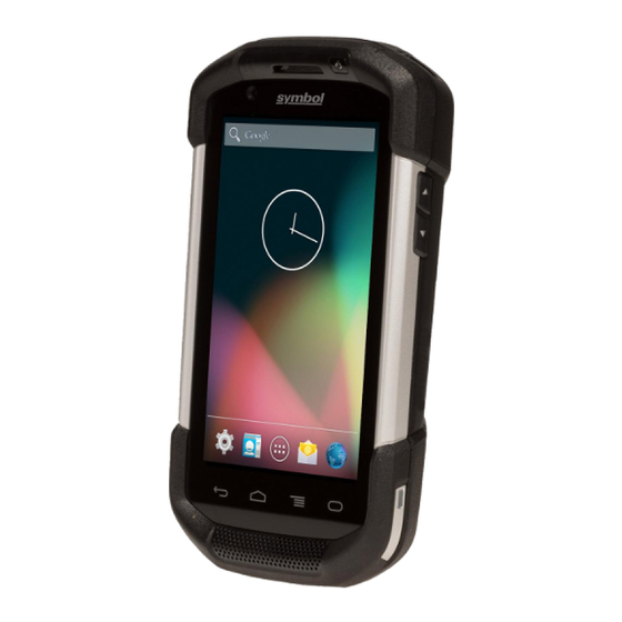
Page 18: Features
Home Button Displays the Home screen with a single press. Displays recently used ap- plications when held for a short period of time. On TC70 with GMS, opens the Google Now screen when held for a short period of time. Microphone Use for communications in Handset mode. - Page 19 Item Function Search Button Opens the search application (programmable). On TC70 with GMS, opens the Recent App screen. Menu Button Opens a menu with items that affect the current screen or application. Light Sensor Determines ambient light for controlling display backlight intensity.
-
Page 20: Setup
Camera Flash Provides illumination for the camera. Setup When and where to use: Perform this procedure to start using the TC70 for the first time. Procedure: 1 Install a micro secure digital (SD) card (optional). 2 Install hand strap (optional). -
Page 21: Installing The Hand Strap And Battery
1 Remove the hand strap filler from the hand strap slot. Store the hand strap filler in a safe place for future replacement. Figure 5: Remove Filler 2 Insert the hand strap plate into the hand strap slot. Figure 6: Insert Hand Strap 3 Insert the battery, bottom first, into the battery compartment in the back of the TC70. -
Page 22: Installing The Battery
6 Place hand strap clip into hand strap mounting slot and pull down until it snaps into place. Figure 9: Secure Hand Strap Clip Installing the Battery Procedure: 1 Insert the battery, bottom first, into the battery compartment in the back of the TC70. -
Page 23: Charging The Battery
The 4,620 mAh battery fully charges in approximately six hours at room temperature. Charge batteries in temperatures from 0 °C to 40 °C (32 °F to 104 °F). The TC70 or accessory always performs battery charging in a safe and intelligent manner. At higher temperatures (e.g. approximately +37 °C (+98 °F)) the TC70 or accessory may for small periods of time alternately enable and disable battery charging to keep the battery at acceptable temperatures. -
Page 24: Charging Indicators
1 Remove any accessory attached to the device. 2 Press the Power button until the menu appears. 3 Touch Power off. 4 If hand strap is attached, slide the hand strap clip up toward the top of the TC70 and then lift. - Page 25 Getting Started | 25 Figure 12: Remove Hand Strap Clip 5 Press the two battery latches in. Figure 13: Press Battery Latches 6 Lift the battery from the TC70.
-
Page 26: Replacing The Microsd Card
1 Press the Power button until the menu appears. 2 Touch Power off. 3 If hand strap is attached, slide the hand strap clip up toward the top of the TC70 and then lift. Figure 15: Remove Hand Strap Clip... -
Page 27: Battery Management
14 Press and hold the Power button to turn on the TC70. Battery Management Note: Prior to checking the battery charge level, remove the TC70 from any AC power source (cradle or cable). To check the charge status of the main battery, on the Home screen touch >... -
Page 28: Low Battery Notification
Some applications include buttons that open screens with settings to adjust power use. Low Battery Notification When the battery charge level drops below 18%, the TC70 displays a notice to connect the TC70 to power. The user should charge the battery using one of the charging accessories. -
Page 29: Battery Optimization
Use the Power Control widget to check and control the status of radios, the screen brightness, and syncing. • Minimize use of applications that keep the TC70 from suspending, for example, music and video applications. Turning Off the Radios Procedure: 1 Press the Power button until the menu appears. -
Page 30: Display Setting
Figure 20: Brightness Dialog Box 5 In the Brightness dialog box, touch Auto to set the TC70 to automatically adjust the brightness using the built-in light sensor. Deselect Auto to set the brightness manually. Use the slider to set a brightness level. -
Page 31: Setting Font Size
Getting Started | 31 5 Select one of the sleep values. • 15 seconds • 30 seconds • 1 minute (default) • 2 minutes • 5 minutes • 10 minutes • 30 minutes 6 Touch Setting Font Size To set the size of the font is system applications: Procedure: Touch Touch... -
Page 32: Touch Mode
Figure 21: Touch Key Light Dialog Box 6 Touch Touch Mode The TC70 display is able to detect touches using a finger, a conductive-tip stylus or gloved finger. Note: A glove can be made of medical latex, leather, cotton or wool. -
Page 33: Setting Notification Led
The Charging/Notification LED lights blue when an application, such as email and VoIP, geneates a programmable notification or to indicate when the TC70 is connected to a Bluetooth device. By default, LED notifications are enabled. To change the notification setting:... - Page 34 34 | Getting Started Figure 24: Volumes Dialog Box - Controls the music and media volume. - Controls the ringtone volume. - Controls the system notification volume. - Controls the alarm clock volume. - Controls the scan good decode beep volume. Bottom row icons: - Places all sounds except media and alarms in silence mode.
-
Page 35: Wake-Up Sources
Wake-Up Sources By default the TC70 wakes from suspend mode when the user presses the power button. The TC70 can be configured to wake when the user presses the PPT or Scan buttons on the left side of the device. - Page 36 36 | Getting Started Figure 26: Wake-Up Sources Dialog Box 4 Touch...
-
Page 37: Chapter 2: Using The Tc70
Chapter Using the TC70 Introduction This chapter explains the buttons, status icons, and controls on the TC70, and provides basic instructions for using the TC70, including resetting the TC70 and entering data. Google Mobile Services Note: This section only applies to TC70 configurations with Google Mobile Services (GMS). - Page 38 Opens browser application. 2 — Browser Icons 3 — All Apps Icon Opens the APPS window. 4 — Shortcut Icons Opens applications installed on the TC70. See Application Shortcuts and Widgets on page 42 for more information. 5 — Widgets Launches stand-alone applications that run on the Home screen.
-
Page 39: Status Bar
Using the TC70 | 39 The Home screen provides four additional screens for placement of widgets and shortcuts. Swipe the screen left or right to view the additional screens. Status Bar The Status bar displays the time, notification icons (left side) and status icons (right side). -
Page 40: Notification Icons
Indicates that a problem with sign-in or sync has occurred. Indicates that the TC70 is uploading data. Indicates that the TC70 is downloading data when animated and download is complete when stat- Indicates that the TC70 is connected via USB cable. -
Page 41: Managing Notifications
Using the TC70 | 41 Icon Description Indicates that DataWedge application is running on the device. Managing Notifications Notification icons report the arrival of new messages, calendar events, and alarms, as well as ongoing events. When a notification occurs, an icon appears in the Status bar with a brief description. See... -
Page 42: Application Shortcuts And Widgets
42 | Using the TC70 Drag the Status bar down from the top of the screen. The Quick Settings icon displays in the top right corner. Touch to display the Quick Settings panel. Figure 30: Quick Settings • Owner – Display the owner’s contact image. Touch to open the owner’s contact information. User must first set up contact information in People application. -
Page 43: Adding An Application Or Widget To The Home Screen
Using the TC70 | 43 Adding an Application or Widget to the Home Screen Procedure: 1 Go to the desired Home screen. Touch 3 Swipe right, if necessary, to find the application icon or widget. 4 Touch and hold the icon or widget until the Home screen appears. -
Page 44: Removing A Folder
44 | Using the TC70 3 Touch Done on the keyboard. 4 Touch anywhere on the Home screen to close the folder. The folder name appears under the folder. Figure 32: Renamed Folder Removing a Folder Procedure: 1 Touch and hold the folder icon until it enlarges. -
Page 45: Using The On-Screen Keyboard
Keys with alternate characters display an ellipsis ( ... ) below the character. Applications The APPS screen displays icons for all installed applications. The table below lists the applications installed on the TC70. Refer to the TC70 Integrator Guide for information on installing and uninstalling application. Table 8: Applications Icon... - Page 46 46 | Using the TC70 Icon Description Bluetooth Pairing Utility – Use to pair the RS507 Hans-free Imager with the TC70 by scan- ning a bar code. Browser - Use to access the Internet or intranet. TC70 Professional (without GMS) only.
- Page 47 Gallery on page 69 for more information. Gmail - Use to send and receive email using a Google email account. TC70 Standard (with GMS) only. Google - Launches Google search application. TC70 Standard (with GMS) only. Google Settings - Use to connect applications to Google account, setup Google Plus account, set location settings, set search features and configure Android Device Manager.
- Page 48 Play Magazines - Use to subscribe to magazine and read on-line. TC70 without GMS only. Play Movies & TV - View movies and video on your device. TC70 Standard (with GMS) on- Play Music - Use to listen to music. TC70 Standard (with GMS) only.
-
Page 49: Accessing Applications
SimulScan Demo - Use to demonstrate the document capture feature of the TC70. Sound Recorder - Use to record audio. TC70 Professional (without GMS) only. StageNow - Allows the TC70 to stage a device for initial use by initiating the deployment of settings, firmware and software. -
Page 50: Switching Between Recent Applications
50 | Using the TC70 Figure 33: APPS Window Example 2 Slide the APPS window left or right to view more application icons. Touch an icon to open the application. Note: See Application Shortcuts and Widgets on page 42 for information on creating a shortcut on the Home screen. -
Page 51: Un-Locking The Screen
Un-Locking the Screen Use the Lock screen to protect access to data on the TC70. Some email account require locking the screen. Refer to the TC70 Integrator Guide for information on setting up the locking feature. The Locking feature functions differently in Single User mode or Multiple User mode. - Page 52 52 | Using the TC70 Figure 35: Lock Screen Figure 36: PIN Screen...
- Page 53 Using the TC70 | 53 Figure 37: Pattern Screen...
-
Page 54: Multiuser Mode
54 | Using the TC70 Figure 38: Password Screen MultiUser Mode With MultiUser login, multiple users can log on to the device with each user having access to various applications and features. When enabled, the Login screen appears after powering on, resetting or after the device wakes from suspend mode. -
Page 55: Multiuser Logout
1 Press and hold the Power button until the menu appears. 2 Touch Reset. 3 The device reboots. Performing a Hard Reset Caution: Performing a hard reset with a SD card installed in the TC70 may cause damage or data corruption to the SD card. -
Page 56: Suspend Mode
3 The TC70 reboots. Suspend Mode The TC70 goes into suspend mode when the user presses the Power button or after a period of inactivity (set in the Display settings window). To wake the TC70 from Suspend mode, press the Power button. - Page 57 Using the TC70 | 57 Figure 41: Lock Screen...
-
Page 59: Chapter 3: Applications
59 | Applications Chapter Applications This section describes the applications installed on the device. File Browser Use the File Browser application to view and mange files on the device. To open File Browser, touch > Figure 42: File Browser Screen The address bar (1) indicates the current folder path. -
Page 60: People
60 | Applications Touch and hold an item to perform an operation on that item. Select one of the options from the File Operations menu: • Information - View detailed information about the file or folder. • Move - Move the file or folder to a new location. •... -
Page 61: Camera
This section provides information for taking photos and recording videos using the integrated digital cameras. Note: If a microSD card is installed, The TC70 saves photos and videos on the microSD card. If a microSD card is not installed, the TC70 saves photos and videos on the internal storage. - Page 62 62 | Applications Touch Figure 44: Camera Mode If necessary, touch the camera options icon and touch To switch between the rear camera and front camera, touch and then 5 Frame the subject on the screen. 6 To zoom in or out, press two fingers on the display and pinch or expand fingers. The zoom controls appear on the screen.
-
Page 63: Taking A Panoramic Photo
Applications | 63 Figure 45: Camera Zoom 7 Touch an area on the screen to focus. The focus circle appears on the screen. The two horizontal bars turn green when in focus. 8 Touch The camera takes a photo and a shutter sound plays. Alternately, touch and hold to focus first, before taking a photo;... -
Page 64: Recording Videos
64 | Applications Figure 46: Panoramic Mode Touch the options bar and touch 4 Frame one side of the scene to capture. 5 Touch and slowly start panning across the area to capture. A small white square appears inside the button indicating the capture is in progress. - Page 65 Applications | 65 Figure 47: Video Mode Touch the options bar and touch To switch between the rear camera and front camera, touch and then 5 Point the camera and frame the scene. 6 To zoom in or out, press two fingers on the display and pinch or expand fingers. The zoom controls appear on the screen.
-
Page 66: Photo Settings
66 | Applications Figure 48: Camera Zoom 7 Touch to start recording. The device starts recording the video. The video time remaining appears in the top left of the screen. 8 Touch to end recording. The video momentarily displays as a thumbnail in the upper right corner. Photo Settings When in Photo mode, photo settings are displayed on screen. - Page 67 Applications | 67 Scene mode - Touch to select a preset combination of camera settings designed for specific scenes. Options: Auto (default), Night, Portrait, Landscape, Steady Photo or Sports. Picture size - Touch to set the size (in pixels) of the photo. Options: 8M pixels (default), 5M pixels, 3M pixels, HD 1080p, 2M pixels, HD 720p, 1M pixels, WVGA, VGA or QVGA.
-
Page 68: Video Settings
68 | Applications Figure 50: Front Photo Setting Options • First Picture size - Touch to set the size (in pixels) of the photo. Options: HD 720p (default), 1M pixels, WVGA, VGA or QVGA. Select Picture Format - Touch to set the format of the photo. Options: Jpeg (default), RAW or YUV420SP. Picture quality - Touch to select picture quality setting. -
Page 69: Gallery
Applications | 69 Fluorescent - Adjust the white balance for florescent lighting. Auto - Adjust the white balance automatically (default). Daylight - Adjust the white balance for daylight. Cloudy - Adjust the white balance for a cloudy environment. Video High FrameRate - Options: Off (default), 60 or 90. Flash mode - Select to turn on flash (default –... -
Page 70: Working With Albums
70 | Applications Figure 53: Gallery — Albums • Touch an album to open it and view its contents. The photos and videos in the album are displayed in chronological order. • Touch a photo or video in an album to view it. •... -
Page 71: Share An Album
Applications | 71 Figure 54: Photos Inside an Album Swipe left or right to scroll images across the screen. Share an Album Procedure: Touch Touch 3 Touch and hold an album until it highlights. 4 Touch other albums as required. Touch . -
Page 72: Deleting An Album
72 | Applications Touch 5 Touch Details. Deleting an Album To delete an album and its contents: Procedure: Touch Touch 3 Touch and hold an album until it highlights. 4 Check other albums to delete. Ensure that other albums are selected. Touch >... -
Page 73: Cropping A Photo
Applications | 73 Figure 55: Photo Example 5 Swipe left or right to view the next or previous photo in the album. 6 Turn the device to view the photo in upright (portrait) or sideways (landscape) orientation. The photo is displayed (but not saved) in the new orientation. -
Page 74: Setting A Photo As A Contact Icon
74 | Applications Figure 56: Cropping Tool 5 Touch Save to save a copy of the cropped photo. The original version is retained. Setting a Photo as a Contact Icon Procedure: Touch Touch 3 Touch an album to open it. 4 Touch the photo to open it. -
Page 75: Deleting A Photo
Applications | 75 3 Touch an album to open it. 4 Touch a photo to open it. Touch 6 Touch the application to use to share the selected photo. The application selected opens with the photo attached to a new message. Deleting a Photo Procedure: Touch... -
Page 76: Sharing A Video
76 | Applications Figure 57: Video Example Touch . The video begins to play. 6 Touch the screen to view the playback controls. Sharing a Video Procedure: Touch Touch 3 Touch an album to open it. 4 Touch a video to open it. Touch . -
Page 77: Datawedge Demonstration
Applications | 77 Touch 3 Touch an album to open it. 4 Touch a video to open it. Touch 6 Touch Delete. 7 Touch OK. DataWedge Demonstration Use DataWedge Demonstration to demonstrate data capture functionality. Figure 58: DataWedge Demonstration Window Table 9: DataWedge Demonstration Icons Icon Description... -
Page 78: Sound Recorder
Opens a menu to view the application information or to set the application DataWedge profile. Note: See the TC70 Integrator Guide for information on DataWedge configuration. Either press the programmable button or touch the yellow scan button to enable data capture. The captured data appears in the text field below the yellow button. - Page 79 Applications | 79 • Group Call: Press and hold the PTT (Talk) button to start communicating with other voice client users. PTT Audible Indicators The following tones provide helpful cues when using the voice client. • Talk Tone: Double chirp. Plays when the Talk button is depressed. This is a prompt for the user to start talking. •...
-
Page 80: Enabling Ptt Communication
80 | Applications Item Description Settings Opens the PTT Express Settings screen. Enable/Disable Turns the PTT service on and off. Switch Notification Icons Indicates the current state of the PTT Express Voice client. Table 11: PTT Express Default User Interface Descriptions Status Icon Description Indicates that PTT Express Voice client is disabled. -
Page 81: Creating A Group Call
Applications | 81 PTT communication may be established as a Group Call. When PTT Express is enabled, the PTT button on the left side of the device is assigned for PTT communication. When the Wired Headset is used, Group Calls can also be initiated using the headset Talk button. -
Page 82: Disabling Ptt Express Voice Client Communication
3 Slide the Enable/Diable Switch to the OFF position. The button changes to OFF. 4 Touch MLog Manager Use MLog Manager to capture log files for diagnostics. See the TC70 Integrator Guide for detailed information on configuring the application. Figure 63: MLog Manager... -
Page 83: Simulscan Demo
Applications | 83 SimulScan Demo The SimulScan application is an out of the box demonstration application included on the device that support SimulScan. The application enables pre-sales personnel to showcase the various features of SimulScan to customers by employing use-cases in the two most popular verticals, Postal/Transportation and Logistics and Manufacturing. The Transportation and Logistics example showcases the OCR and OMR features. - Page 84 84 | Applications Figure 65: Postal, Transportation and Logistics Form Procedure: 1 Place the form on a flat surface. 2 On the device, launch SimulScan Demo application. 3 Touch the Menu icon in the top right corner of the screen. 4 Touch Postal, Transportation &...
-
Page 85: Manufacturing Example
Applications | 85 10 Tap the screen to start the data capture. When completed, the device beeps and the data from the form displays. Figure 67: Postal Data Screen 11 Touch the text boxes to correct any errors. Note: if there are too many errors, touch Rescan to perform the capture again. -
Page 86: Settings
86 | Applications 4 On the device, launch SimulScan Demo application. 5 Touch the Menu icon in the top right corner of the screen. 6 Touch Manufacturing. 7 Touch Start SimulScan. 8 Point the top of the device at the document and center the target on the document. 9 Hold the device steady. -
Page 87: Demo Customization
Applications | 87 Demo Customization Before creating a customized demo, first: • Create a template using the Template Builder tool. • Copy a company logo and image to the device storage location. Procedure: 1 Touch Menu icon. 2 Touch Custom Demo Setup. Figure 71: Custom Demo Setup Screen 3 In the Name text box, enter a name for the custom demo. -
Page 88: Elemez
88 | Applications states, wireless logging, cellular logging, TCP dumps, Bluetooth logging, GPS logging, logcat, FTP push/pull, ANR dumps, etc. All logs and files generated are saved onto flash storage on the device (internal or external). Figure 72: RxLogger Elemez Note: Elemez collects specific device information in the background and sends this information to us to help improve product functionality. -
Page 89: Disabling Elemez Data Collection
Applications | 89 Figure 73: Elemez Application Disabling Elemez Data Collection The user can disable the Elemez application from collection specific data in the background and sending it to Zebra Technologies. Procedure: 1 From the Home screen, touch 2 Touch Manage Apps. 3 Swipe left or right until the ALL tab displays. - Page 90 90 | Applications Touch 9 Touch Enable Elemez.
-
Page 91: Chapter 4: Data Capture
Pick List Mode: This mode allows the user to selectively decode a bar code when more than one bar code is in the TC70 ’s field of view. To accomplish this, move the aiming crosshair or dot over the required bar code to decode only this bar code. -
Page 92: Scanning Considerations
Procedure: 1 Ensure that an application is open on the TC70 and a text field is in focus (text cursor in text field). 2 Point the exit window on the top of the TC70 at a bar code. - Page 93 3 Press and hold the scan button. The red laser aiming pattern turns on to assist in aiming. Note: When the TC70 is in Picklist mode, the imager does not decode the bar code until the crosshair or aiming dot touches the bar code.
-
Page 94: Bar Code Capture With Rs507 Hands-Free Imager
94 | Data Capture Note: Imager decoding usually occurs instantaneously. The TC70 repeats the steps required to take a digital picture (image) of a poor or difficult bar code as long as the scan button remains pressed. 7 The bar code content data displays in the text field. -
Page 95: Pairing The Rs507 Hands-Fee Imager Using Ssi
The RS507 emits a high/low/high/low beeps. The Scan LED flashes green indicating that the RS507 is attempting to establish connection with the TC70. When connection is established, the Scan LED turns off and the RS507 emits one string of low/high beeps. -
Page 96: Pairing The Rs507 Hands-Free Imager Bluetooth Hid
The captured bar code data is converted to keystrokes and sent to the target application as if it was typed on the keypad. To configure DataWedge refer to the TC70 Integrator Guide. Enabling DataWedge... -
Page 97: Disabling Datawedge
Data Capture | 97 4 Touch Settings. 5 Touch the DataWedge enabled checkbox. A blue checkmark appears in the checkbox indicating that DataWedge is enabled. 6 Touch Disabling DataWedge Procedure: Touch Touch 3 Touch 4 Touch Settings. 5 Touch the DataWedge enabled checkbox. The blue checkmark disappears from the checkbox indicating that DataWedge is disabled. -
Page 99: Chapter 5: Wireless
Wireless local area networks (WLANs) allow the TC70 to communicate wirelessly inside a building. Before using the TC70 on a WLAN, the facility must be set up with the required hardware to run the WLAN (sometimes known as infrastructure). The infrastructure and the TC70 must both be properly configured to enable this communication. - Page 100 100 | Wireless Figure 83: Settings Screen 3 Slide the Wi-Fi switch to the ON position. Touch Wi-Fi. The TC70 searches for WLANs in the area and lists them.
-
Page 101: Configuring A Wi-Fi Network
Connect. See the system administrator for more information. The TC70 obtains a network address and other required information from the network using the dynamic host configuration protocol (DHCP) protocol. To configure the TC70 with a fixed internet protocol (IP) address, See Configuring the Device to Use a Static IP Address on page 104. - Page 102 102 | Wireless Figure 85: WLAN Network Security Dialog Box 8 If the network security is WEP or WPA/WPS2 PSK, enter the required password and then touch Connect. 9 If the network security is 802.1x EAP: • Touch the EAP method drop-down list and select PEAP, TLS, TTLS, PWD, LEAP or FAST. •...
-
Page 103: Manually Adding A Wi-Fi Network
Wireless | 103 Manually Adding a Wi-Fi Network Manually add a Wi-Fi network if the network does not broadcast its name (SSID) or to add a Wi-Fi network when out of range. Procedure: Touch Touch Wi-Fi. 3 Slide the Wi-Fi switch to the On position. 4 Touch + at the bottom of the screen. -
Page 104: Configuring The Device To Use A Static Ip Address
104 | Wireless 2 Touch Show advanced options checkbox. 3 Touch Proxy settings and select Manual. Figure 86: Proxy Settings 4 In the Proxy hostname text box, enter the address of the proxy server. 5 In the Proxy port text box, enter the port number for the proxy server. Note: When entering proxy addresses the Bypass proxy for field, do not use spaces or carriage returns between addresses. -
Page 105: Advanced Wi-Fi Settings
Wireless | 105 Figure 87: Static IP Settings 4 In the IP address text box, enter an IP address for the device. 5 If required, in the Gateway text box, enter a gateway address for the device. 6 If required, in the Network prefix length text box, enter a the prefix length. 7 If required, in the DNS 1 text box, enter a Domain Name System (DNS) address. - Page 106 106 | Wireless Available channels (5 GHz) - Use to select specific channels. Touch to display the Available channels menu. Select specific channels. Touch OK. • Logging Advanced Logging – Touch to enable advanced logging. Advanced logging Wireless logs - Use to capture Wi-Fi log files. + Fusion Logger - Touch to open the Fusion Logger application.
-
Page 107: Remove A Wi-Fi Network
Bluetooth enabled devices such as printers, access points, and other mobile devices. The TC70 support Bluetooth Low Energy. Bluetooth Low Energy is targeted at applications in the healthcare, fitness, security, and home entertainment industries. It provides reduced power consumption and cost while maintaining standard Bluetooth range. -
Page 108: Bluetooth Profiles
Suspend - When the TC70 goes into suspend mode, the Bluetooth radio stays on. • Airplane Mode - When the TC70 is placed in Airplane Mode, the Bluetooth radio turns off. When Airplane mode is disabled, the Bluetooth radio returns to the prior state. When in Airplane Mode, the Bluetooth radio can be... -
Page 109: Bluetooth Radio Power
4 Touch Discovering Bluetooth Device(s) The TC70 can receive information from discovered devices without pairing. However, once paired, the TC70 and a paired device exchange information automatically when the Bluetooth radio is on. To find Bluetooth devices in the area: Procedure: 1 Ensure that Bluetooth is enabled on both devices. -
Page 110: Changing The Bluetooth Name
11 The Bluetooth device is added to the Bluetooth devices list and a trusted (“paired”) connection is established. Changing the Bluetooth Name By default, the TC70 has a generic Bluetooth name that is visible to other devices when connected. Procedure:... -
Page 111: Selecting Profiles On The Bluetooth Device
NFC/HF RFID is a short-range wireless connectivity technology standard that enables secure transaction between a reader and a contactless smartcard. The technology is based on ISO/IEC 14443 type A and B (proximity) and ISO/IEC 15693 (vicinity) standards, using the HF 13.56 MHz unlicensed band. The TC70 support 3 operating modes: •... -
Page 112: Reading Nfc Cards
Exchange data with another NFC device. • Emulate contactless card such as payment, ticket or SmartPoster. The TC70 NFC antenna is uniquely positioned to read NFC cards from the top of the device while being held in the user's hand. Reading NFC Cards Procedure: 1 Launch an NFC enabled application. -
Page 113: Enterprise Nfc Settings
Wireless | 113 Figure 93: Sharing Data Using NFC When the devices connect, you hear a sound, the image on the screen reduces in size, the message Touch to beam appears. 3 Touch anywhere on the screen. The transfer begins. Enterprise NFC Settings The Enterprise NFC Settings provides advanced configuration of the NFC radio. - Page 114 114 | Wireless Figure 95: Enterprise NFC Settings Screen • Reader Mode – Touch to open the Reader Mode setting screen. • Enable P2P mode – Enable or disable peer to peer mode. Default: Enabled. • Card Emulation Mode – Enable or disable card emulation mode. Default: Disabled. •...
-
Page 115: Data Usage
Wireless | 115 Figure 96: Reader Mode Settings • Supported Cards – Touch to select the type of NFC cards to support. Options: All Cards (default), Type A, Type B, Type F or Type V. • NDEF Support Skip NDEF – Enables or disables the use of NFC Forum tag types 1 through 4. Default: Disabled. •... - Page 116 116 | Wireless Figure 97: Data Usage Screen Touch the data usage cycle to choose a different cycle. This date range is the period of time for which the graph displays data usage. The vertical white lines on the graph show a period of time within the data usage cycle. This range determines the usage amount displayed just below the graph.
-
Page 117: Chapter 6: Accessories
117 | Accessories Chapter Accessories This chapter provides information for using the accessories for the device. Accessories This table lists the accessories available for the TC70. Table 12: TC70 Accessories Accessory Part Number Description Cradles 2-Slot Charge Only Cra- CRD-TC7X-SEC2U1–01 Provides device and spare battery charging. - Page 118 118 | Accessories Accessory Part Number Description Payment Magnetic Stripe Reader MSR-TC7X-SNP1-01 Captures data from magnetic stripe cards. Charge and Communication Cables Charging Cable Cup CHG-TC7X-CBL1-01 Provides power to the device. Use with power supply, p/n PWRS-14000-249R, sold separately. Snap-On USB Cable CBL-TC7X-CBL1-01 Provides power to the device and USB communication with a host computer.
-
Page 119: 2-Slot Charge Only Cradle
Accessories | 119 Accessory Part Number Description Power Supply PWRS-14000-241R Provides power to the 5-Slot Charge Only cradle and the 5-Slot Ethernet Cradle. Requires DC Line Cord, p/n 50– 16002–029R and country specific three wire grounded AC line cord sold separately. DC Line Cord 50-16002-029R Provides power from the power supply to the 5-Slot... -
Page 120: Charging The Spare Battery
120 | Accessories Figure 99: Battery Charging 2 Ensure the device is seated properly. Charging the Spare Battery Procedure: 1 Insert the battery into the right slot to begin charging. Figure 100: Spare Battery Charging 2 Ensure the battery is seated properly. -
Page 121: Battery Charging
Accessories | 121 Battery Charging Main Battery Charging The device’s Charging/Notification LED indicates the status of the battery charging in the device. The 4,620 mAh battery fully charges in less than six hours at room temperature. Spare Battery Charging The Spare battery Charging LED on the cup indicates the status of the spare battery charging. The 4,620 mAh battery fully charges in less than six hours at room temperature. -
Page 122: Charging The Device
122 | Accessories Figure 101: 2-Slot USB/Ethernet Cradle Power LED – Lights green indicating that the cradle is receiving power. Spare Battery Charging LED Charging the Device Procedure: 1 Place the bottom of the device into the base. -
Page 123: Charging The Spare Battery
Accessories | 123 Figure 102: Battery Charging 2 Rotate the top of the device until the connector on the back of the device mates with the connector on the cradle. 3 Ensure the device is connected properly. The charging Charging/Notification LED on the device begins blinking amber indicating that the device is charging. -
Page 124: Battery Charging
124 | Accessories Figure 103: Spare Battery Charging 2 Ensure the battery is seated properly. Battery Charging Main Battery Charging The device’s Charging/Notification LED indicates the status of the battery charging in the device. The 4,620 mAh battery fully charges in less than six hours at room temperature. Spare Battery Charging The Spare battery Charging LED on the cup indicates the status of the spare battery charging. -
Page 125: Usb/Ethernet Communication
Accessories | 125 Charging Temperature Charge batteries in temperatures from 0 °C to 40 °C (32 °F to 104 °F). The device or cradle always performs battery charging in a safe and intelligent manner. At higher temperatures (e.g. approximately +37 °C (+98 °F)) the device or cradle may for small periods of time alternately enable and disable battery charging to keep the battery at acceptable temperatures. -
Page 126: Establishing Ethernet Connection
Provides 5 VDC power for operating the TC70. • Simultaneously charges up to five TC70s and up to four TC70s and on 4-Slot Battery Charger using the Battery Charger Adapter. See the TC70 Integrator Guide for information on installing the 4-Slot Battery Charger onto the cradle. •... -
Page 127: Charging The Tc70
Accessories | 127 Charging the TC70 Procedure: 1 Insert the TC70 into a slot to begin charging. Figure 107: TC70 Battery Charging... -
Page 128: Battery Charging
128 | Accessories Figure 108: 5-Slot Charge Only Cradle with Four Slot Battery Charger 2 Ensure the TC70 is seated properly. Note: See the TC70 Integrator Guide for information on installing the 4-Slot Battery Charger onto the cradle. Battery Charging Main Battery Charging The device’s Charging/Notification LED indicates the status of the battery charging in the device. -
Page 129: 5-Slot Ethernet Cradle
Connects the device (up to five) to an Ethernet network. • Simultaneously charges up to five TC70s and up to fourTC70s and on 4-Slot Battery Charger using the Battery Charger Adapter. See the TC70 Integrator Guide for information on installing the 4-Slot Battery Charger onto the cradle. -
Page 130: Charging The Tc70
130 | Accessories Figure 109: 5-Slot Ethernet Cradle 1000 LED – Indicates 1 Gbps data rate. 100/10 LED – Indicates 100 Mbps or 10 Mbps data rate. Charging the TC70 Procedure: 1 Insert the TC70 into a slot to begin charging. - Page 131 Accessories | 131 Figure 110: TC70 Battery Charging 2 Ensure the TC70 is seated properly. Figure 111: 5-Slot Ethernet Cradle with 4-Slot Battery Charger...
-
Page 132: Battery Charging
132 | Accessories Note: See the TC70 Integrator Guide for information on installing the 4-Slot Battery Charger onto the cradle. Battery Charging Main Battery Charging The device’s Charging/Notification LED indicates the status of the battery charging in the device. The 4,620 mAh battery fully charges in less than six hours at room temperature. -
Page 133: Led Indicators
On/Blink 10 Mbps On/Blink 4-Slot Battery Charger This section describes how to use the 4-Slot Battery Charger to charge up to four TC70 batteries. Charging Spare Batteries Procedure: 1 Connect the charger to a power source. 2 Insert the battery into a battery charging well and gently press down on the battery to ensure proper contact. -
Page 134: Battery Charging
The battery charger indicates when charging is disabled due to abnormal temperatures via its LED. Magnetic Stripe Reader The MSR snaps on to the back of the TC70 and removes easily when not in use. When attached to the TC70, the MSR allows the TC70 to capture data from magnetic stripe cards. -
Page 135: Removing The Msr
Accessories | 135 Figure 113: MSR Installation 2 Rotate the MSR down and press down until it snaps into position. 3 Using a flat end plastic tool, slide the lock switch down to lock the MSR. Figure 114: Lock MSR Removing the MSR Procedure: 1 Using a flat end plastic tool, slide the lock switch up to unlock the MSR. -
Page 136: Reading Magnetic Stripe Cards
136 | Accessories Figure 116: Remove MSR 3 Rotate the MSR away from the TC70 and lift. Reading Magnetic Stripe Cards Use the integrated MSR to read magnetic stripe card. Procedure: 1 Ensure that MSR input is enabled in DataWedge and the cursor is in a text field. -
Page 137: Mm Audio Adapter
2.5 mm Audio Adapter The 2.5 mm Audio Adapter snaps onto the back of the TC70 and removes easily when not in use. When attached to the TC70, the Audio Adapter allows a user to connect a wired headset to the TC70. -
Page 138: Connecting A Headset To The Audio Adapter
138 | Accessories Figure 118: Audio Adapter Installation 2 Rotate the Audio Adapter down and press down until it snaps into position. Figure 119: Rotate Audio Adapter onto TC70 Connecting a Headset to the Audio Adapter Procedure: 1 Lift the rubber plug from the audio jack. -
Page 139: Device With Audio Adapter In Holster
3 Press the headset wire into the wire holder on the Audio Adapter. Figure 121: Device with Audio Adapter in Holster When using the TC70 and the audio adapter in a holster, ensure that the display faces in and the headset cable is securely attached to the audio adapter. -
Page 140: Removing The 2.5 Mm Audio Adapter
3.5 mm Audio Adapter The 3.5 mm Audio Adapter snaps onto the back of the TC70 and removes easily when not in use. When attached to the TC70, the 3.55 mm Audio Adapter allows a user to connect a wired headset to the TC70. -
Page 141: Attaching The 3.5 Mm Audio Adapter
Attaching the 3.5 mm Audio Adapter Procedure: 1 Align the top mounting points on the 3.5 mm Audio Adapter with the mounting slots on the TC70. Figure 124: Audio Adapter Installation 2 Rotate the Audio Adapter down and press down until it snaps into position. -
Page 142: Device With 3.5 Mm Audio Adapter In Holster
Figure 126: Connect Adapter Cable to Audio Adapter Device with 3.5 mm Audio Adapter in Holster When using the TC70 and the audio adapter in a holster, ensure that the display faces in and the headset cable is securely attached to the audio adapter. -
Page 143: Removing The 3.5 Mm Audio Adapter
Figure 127: Device with 3.5 mm Audio Adapter in Holster Removing the 3.5 mm Audio Adapter Procedure: 1 Disconnect headset plug from 3.5 mm Audio Adapter. 2 Lift the bottom of the Audio Adapter away from the TC70. Figure 128: Remove Audio Adapter from TC70... -
Page 144: Snap-On Usb Cable
Snap-On USB Cable The Snap-On USB Cable snaps on to the back of the TC70 and removes easily when not in use. When attached to the TC70, the Snap-On USB Cable allows the TC70 to transfer data to a host computer and provide power for charging the TC70. -
Page 145: Charging The Tc70
2 Connect the USB connector of the cable to a host computer. Charging the TC70 Procedure: 1 Connect the Snap-On USB Cable to the TC70. 2 Connect the power supply to the Snap-On USB Cable Figure 132: Power Setup 3 Connect to the power supply to an AC outlet. -
Page 146: Battery Charging
146 | Accessories Figure 133: Press Down on Cable 2 Rotate away from the TC70. The magnetics release the cable from the TC70. Figure 134: Remove Cable from TC70 Battery Charging Main Battery Charging The device’s Charging/Notification LED indicates the status of the battery charging in the device. - Page 147 Figure 135: TC70 Charging 2 Ensure the TC70 is seated properly. 3 Slide the two yellow locking tabs up to lock the cable to the TC70. Figure 136: Lock Cable Cup 4 Connect the power supply to the Charging Cable Cup and to a power source.
-
Page 148: Battery Charging
Snap-On DEX Cable The Snap-On DEX Cable snaps on to the back of the TC70 and removes easily when not in use. When attached to the TC70, the Snap-On DEX Cable provides electronic data exchange with devices such as vending machines. -
Page 149: Connecting To Tc70
1 Align the top mounting points on the cable with the mounting slots on the TC70. Figure 138: Cable Installation 2 Rotate the cable down and press until it snaps into place. Magnetics hold the cable to the TC70. Figure 139: Cable Attached to TC70... -
Page 150: Disconnecting From Tc70
Figure 140: DEX Cable Connection Disconnecting from TC70 Procedure: 1 Press down on the cable. Figure 141: Press Down on Cable 2 Rotate away from the TC70. The magnetics release the cable from the TC70. Figure 142: Remove Cable from TC70... -
Page 151: Trigger Handle
Accessories | 151 Trigger Handle The Trigger Handle adds a gun-style handle with a scanning trigger to the device. It increases comfort when using the device in scan-intensive applications for extended periods of time. Figure 143: Trigger Handle Trigger Latch Release button Trigger Handle Plate Installing the Trigger Handle Plate... -
Page 152: Inserting The Device Into The Trigger Handle
152 | Accessories Figure 145: Insert Trigger Handle Plate 8 Insert the battery, bottom first, into the battery compartment in the back of the device. 9 Rotate the top of the battery into the battery compartment. 10 Press the battery down into the battery compartment until the battery release latches snap into place. Inserting the Device into the Trigger Handle Procedure: 1 Align the back of the Trigger handle with the Trigger Mounting Plate. -
Page 153: Removing The Device From The Trigger Handle
Accessories | 153 Figure 147: Rotate Device onto Trigger Handle Removing the Device from the Trigger Handle Procedure: 1 Press both Trigger Handle release latches. Figure 148: Press Release Latches 2 Rotate the device up and remove from the Trigger handle. 3 Rotate the device down and press down until it snaps into place. - Page 154 154 | Accessories Figure 149: Rotate Device onto Trigger Handle...
-
Page 155: Chapter 7: Maintenance And Troubleshooting
Do not store or use the TC70 in any location that is dusty, damp, or wet. • Use a soft lens cloth to clean the TC70. If the surface of the TC70 screen becomes soiled, clean it with a soft cloth moistened with a diluted window-cleaning solution. -
Page 156: Cleaning Instructions
156 | Maintenance and Troubleshooting • Battery usage by children should be supervised. • Please follow local regulations to properly dispose of used re-chargeable batteries. • Do not dispose of batteries in fire. • In the event of a battery leak, do not allow the liquid to come in contact with the skin or eyes. If contact has been made, wash the affected area with large amounts of water and seek medical advice. -
Page 157: Cleaning The Tc70
They may be cleaned as frequently as required, but it is advisable to clean the camera window periodically when used in dirty environments to ensure optimum performance. Cleaning the TC70 Housing Using the alcohol wipes, wipe the housing including buttons. -
Page 158: Troubleshooting
LEDs blink. charged. Battery did not charge. Battery failed. Replace battery. If the TC70 still does not operate, perform a reset. TC70 removed from cra- Insert TC70 in cradle. The 4,620 mAh battery fully charges in dle while battery was less than six hours at room temperature. - Page 159 Refer to the EMDK or DataWedge application. TC70 is not programmed If the TC70 does not beep on a good decode, set the applica- to generate a beep. tion to generate a beep on good decode.
- Page 160 160 | Maintenance and Troubleshooting Problem Cause Solution Cannot unlock TC70. User enters incorrect pass- If the user enters an incorrect password eight times, the user is word. requested to enter a code before trying again. If the user forgot the password, contact system administrator.
-
Page 161: Chapter 8: Technical Specifications
161 | Technical Specifications Chapter Technical Specifications The following sections provide technical specification for the device. TC70 Table 21: TC70 Technical Specifications Item Description Physical Characteristics Dimensions Height: 161 mm (6.3 in.) Width: 84 mm (3.3 in.) Depth: 28 mm (1.1 in.) Weight 376 g (13.3 oz) - Page 162 162 | Technical Specifications Item Description Charging Temperature 0° C to 40° C (32°F to 104°F) Humidity 5 to 85% non-condensing Drop Specification 6 ft./1.8 m drop to concrete across full operating temperature range Tumble 2,000 3.2 ft./1.0 m tumbles; meets and exceeds IEC tumble specifications Electrostatic Discharge (ESD) +/-20kVdc air discharge, +/-10kVdc direct discharge, +/-10kVdc indirect discharge...
- Page 163 Technical Specifications | 163 Item Description Communication and Messaging Workforce Connect Push-to-Talk Express Client (included) for instant push-to-talk communications right out of the box WorkForce Connect Voice Client* (sold separately). 2D Imager Engine (SE4750-SR) Specifications Field of View Horizontal - 48.0° Vertical - 36.7°...
- Page 166 Zebra Technologies Corporation 3 Overlook Point Lincolnshire IL, 60069 U.S.A. http://www.zebra.com Zebra and the stylized Zebra head are trademarks of ZIH Corp., registered in many jurisdictions worldwide. The Symbol logo is a registered trademark of Symbol Technologies, Inc., a Zebra Technologies company.