Motorola AP650 Installation Manual
Hide thumbs
Also See for AP650:
- Installation manual (38 pages) ,
- Installation manual (36 pages) ,
- Reference manual (954 pages)
Table of Contents
Advertisement
Advertisement
Table of Contents

Related Manuals for Motorola AP650


Summary of Contents for Motorola AP650
- Page 1 AP650 Access Point INSTALLATION GUIDE...
- Page 2 AP650 Access Point Zebra and the Zebra head graphic are registered trademarks of ZIH Corp. The Symbol logo is a registered trademark of Symbol Technologies, Inc., a Zebra Technologies company. © 2015 Symbol Technologies, Inc.
-
Page 3: Table Of Contents
2.7 External Antenna Model Suspended Ceiling Tile (Plenum) Mount Instructions ......... 14 2.7.1 Suspended Ceiling Mount Hardware ..................14 2.7.2 Ceiling Mount Procedure ......................15 2.8 AP650 External Antenna Model Antenna Options ................16 2.9 LED Indicators ............................17 2.9.1 WiNG 4.x LED States ......................... 17 2.9.2 WiNG 5.x LED States ......................... - Page 4 AP650 Access Point 4.3.1 Safety Information ........................24 4.4 International ............................24 4.5 EU ................................. 24 4.6 US and Canada ............................. 24 4.7 Power Supply ............................24 4.8 Radio Frequency Interference Requirements—FCC ................25 4.9 Radio Frequency Interference Requirements – Canada ..............25 4.9.1 Radio Transmitters ........................
-
Page 5: Introduction
The light pipe fits through a hole in the ceiling tile to provide a view of the unit’s status lights. The AP650 access point receives all power and transfers data through the same CAT-5 or better Ethernet cable. -
Page 6: Ap650 Package Contents
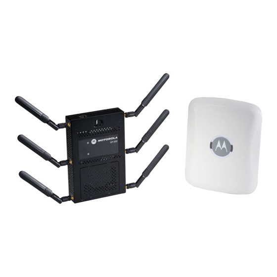
AP650 Access Point 1.4 AP650 Package Contents The AP650 model Access Point comes in four configurations, two Integrated Antenna models and two External Antenna models. The contents of the package differ between the Integrated Antenna model and the External Antenna model. -
Page 7: Features
• Lock port for Kensington® style Security Lock The AP650 access point has one RJ-45 connector supporting an 10/100/1000 Ethernet port and requires 802.3af-compliant power from an external source. When operating in a Gigabit Ethernet environment CAT-5e or CAT-6 cable NOTE is required for Gigabit operation. -
Page 8: Hardware Installation
Hardware Installation 2.1 Installation Instructions The AP650 Access Point mounts either on a wall with wide-shoulder screws or on a suspended ceiling T-bar. This unit is not designed for mounting on a desk. To prepare for installation, perform the following steps: 1. -
Page 9: Access Point Placement
This mounting requires hanging the AP650 Access Point along its width or length using the two slots on the bottom of the unit. The AP650 can be mounted on to any plaster, wood, or cement wall surface using the provided wall anchors when necessary. -
Page 10: Wall Mount Procedure
1. Orient the case on the wall by its width or length. Incorrect Orientation Correct Orientation To ensure proper operation of the AP650 Access Point ensure that the CAUTION thin Access Point is mounted in the correct orientation as shown above. - Page 11 Installation Guide 3. At each point, drill a hole in the wall, insert an anchor, screw into the anchor the wall mounting screw and stop when there is 1mm between the screw head and the wall. When pre-drilling a hole the recommended hole size is 2.8mm (0.11in.) if NOTE the screws are going directly into the wall and 6mm (0.23in.) if the provided wall anchors are being used.
-
Page 12: Integrated Antenna Model Suspended Ceiling T-Bar Mount Instructions
2.6 External Antenna Model Wall Mount Instructions Wall mounting requires hanging the AP650 access point along its width or length using the pair of slots on the bottom of the unit. The AP650 can be mounted onto any plaster, wood, or cement wall surface using the provided wall anchors when necessary. -
Page 13: Wall Mount Procedure
Installation Guide • Two wall anchors • Safety wire (recommended) and security cable (optional) In the event that the original mounting screws are lost, the following NOTE screws can be used instead: (ANSI Standard) #6-18 X 0.875in. Type A or AB Self-Tapping Screw, or (ANSI Standard Metric) M3.5 X 0.6 X 20mm Type D Self-Tapping Screw. -
Page 14: External Antenna Model Suspended Ceiling Tile (Plenum) Mount Instructions
2.7 External Antenna Model Suspended Ceiling Tile (Plenum) Mount Instructions Ceiling mount requires placing the AP650 access point above a suspended ceiling and installing the provided light pipe for viewing the status lights of the unit. Notes or warnings about suspended ceiling mounts apply to all NOTE installations where the unit is placed on suspended ceiling tile. -
Page 15: Ceiling Mount Procedure
Installation Guide 2.7.2 Ceiling Mount Procedure Light Pipe Ceiling Tile Badge 1. If possible, remove the ceiling tile from its frame and place it, finished side down, on a work surface. 2. If required, install a safety wire, between 1.5mm (.06in.) and 2.5mm (.10in.) in diameter, in the ceiling space. 3. -
Page 16: Ap650 External Antenna Model Antenna Options
AP650 Access Point 2.8 AP650 External Antenna Model Antenna Options Select an antenna model best suited to the intended operational environment of your Access Point. On single radio versions, the R-SMA connectors can support both bands and should be connected to a R-SMA dual-band antenna or an appropriate single band antenna. -
Page 17: Led Indicators
Installation Guide 2.9 LED Indicators Both the Integrated Antenna model and the External Antenna model have LED activity indicators on the front of the case for use with wall mount. With the External Antenna model unit mounted above a ceiling, LEDs are at the center of an oval badge on the ceiling;... - Page 18 AP650 Access Point 5 GHz Activity LED 2.4 GHz Activity LED Task (Amber) (Green) Firmware Upgrade Solid Sensor Mode (Connected to server) Blink (On 1 second, Off 1 second) Sensor Mode (Not connected to server) Blink (On 1 second, Off 5...
-
Page 19: Specifications
Installation Guide Specifications 3.1 AP650 External Antenna Model Electrical Characteristics An AP650 External Antenna model Access Point has the following electrical characteristics: Operating Current & 180ma- 270ma @ 48VDC Voltage 3.2 AP650 External Antenna Model Physical Characteristics An AP650 External Antenna model Access Point has the following physical characteristics: Dimensions 8.50 in. -
Page 20: Ap650 Integrated Antenna Model Electrical Characteristics
180ma- 270ma @ 48VDC Voltage 3.4 AP650 Integrated Antenna Model Physical Characteristics An AP650 Integrated Antenna model Access Point has the following physical characteristics: Dimensions 9.50 in. Depth x 7.5 in. Width x 1.9 in. Height 24.13 cm Depth x 19.05 cm Width x 4.83 cm Height... -
Page 21: Radio Characteristics
Installation Guide 3.5 Radio Characteristics An AP650 model Access Point has the following radio characteristics: Operating Channels All channels from 4920 MHz to 5825 MHz except channel 52 -64 Channels 1-13 (2412-2472 MHz) Channel 14 (2484 MHz) Japan only Actual operating frequencies depend on regulatory approval for the country of use. -
Page 22: Regulatory Information
AP650 Access Point Regulatory Information This guide applies to Model Number AP-650 All Zebra devices are designed to be compliant with rules and regulations in locations they are sold and will be labeled as required. Local language translations are available at the following website: www.zebra.com/support... -
Page 23: Frequency Of Operation - Fcc And Ic
Installation Guide 4.1.2 Frequency of Operation – FCC and IC 5 GHz Only The use on UNII (Unlicensed National Information Infrastructure) Band 1 5150-5250 MHz and Band 3 5470 - 5725 MHz is restricted to indoor use only, any other use will make the operation of this device illegal. Devices using the 5470 –... -
Page 24: Rf Exposure Guidelines
AP650 Access Point Other Medical Devices Please consult your physician or the manufacturer of the medical device, to determine if the operation of your wireless product may interfere with the medical device. 4.3 RF Exposure Guidelines 4.3.1 Safety Information Reducing RF Exposure—Use Properly Only operate the device in accordance with the instructions supplied. -
Page 25: Radio Frequency Interference Requirements-Fcc
Installation Guide 4.8 Radio Frequency Interference Requirements—FCC This equipment has been tested and found to comply with the limits for a Class B digital device, pursuant to Part 15 of the FCC rules. These limits are designed to provide reasonable protection against harmful interference in a residential installation. -
Page 26: Ce Marking And European Economic Area (Eea)
AP650 Access Point 4.10 CE Marking and European Economic Area (EEA) The use of 2.4 GHz RLAN’s, for use through the EEA, have the following restrictions: • Maximum radiated transmit power of 100 mW EIRP in the frequency range 2.400 -2.4835 GHz. -
Page 27: Waste Electrical And Electronic Equipment (Weee)
Installation Guide 4.12 Waste Electrical and Electronic Equipment (WEEE) English: For EU Customers: All products at the end of their life must be returned to Zebra for recycling. For information on how to return product, please go to: www.zebra.com/weee. Français: Clients de l'Union Européenne: Tous les produits en fin de cycle de vie doivent être retournés à... - Page 28 AP650 Access Point Magyar: Az EU-ban vásárlóknak: Minden tönkrement terméket a Zebra vállalathoz kell eljuttatni újrahasznosítás céljából. A termék visszajuttatásának módjával kapcsolatos tudnivalókért látogasson el a www.zebra.com/weee weboldalra. Svenska: För kunder inom EU: Alla produkter som uppnått sin livslängd måste returneras till Zebra för återvinning.
-
Page 29: Turkish Weee Statement Of Compliance
Installation Guide 4.13 TURKISH WEEE Statement of Compliance EEE Yönetmeliğine Uygundur 4.14 Japan (VCCI) - Voluntary Control Council for Interference Class B ITE この装置は、情報処理装置等電波障害自主規制協議会 (VCCI)の基準に基づくク ラス B 情報技術装置です。この装置は、家庭環境で使用することを目的としています が、この装置がラジオやテレビジョン受信機に近接して使用されると、受信障害を引 き起こすことがあります。 取扱説明書に従って正しい取り扱いをして下さい。 This is a Class B product based on the standard of the Voluntary Control Council for Interference from Information Technology Equipment (VCCI). -
Page 30: Chile
AP650 Access Point Para maiores informações sobre ANATEL consulte o site: http://www.anatel.gov.br 4.16.3 Chile “Este equipo cumple con la Resolución No 403 de 2008, de la Subsecretaria de telecomunicaciones, relativa a radiaciones electromagnéticas.”. "This device complies with the Resolution Not 403 of 2008, of the Undersecretary of telecommunications, relating to electromagnetic radiation.”... -
Page 31: Korea
Installation Guide The low power radio-frequency devices must be susceptible with the interference from legal communications or ISM radio wave radiated devices. 臺灣 低功率電波輻射性電機管理辦法 第十二條 經型式認證合格之低功率射頻電機,非經許可,公司、商號或使用者均不得擅自 變更頻率、加大功率或變更原設計之特性及功能。 第十四條 低功率射頻電機之使用不得影響飛航安全及干擾合法通信;經發現有干擾現象 時,應立即停用,並改善至無干擾時方得繼續使用。 前項合法通信,指依電信規定作業之無線電通信。 低功率射頻電機須忍受合法通信或工業、科學及醫療用電波輻射性電機設備之干 擾。 Wireless device operate in the frequency band of 5.25-5.35 GHz, limited for Indoor use only. 在... -
Page 32: Support
AP650 Access Point Support If you have a problem with your equipment, contact support for your region. Contact information is available at: www.zebra.com/support When contacting Support, please provide the following information: • Serial number of the unit • Model number or product name •... -
Page 33: Ap-650 Access Point China Rohs Compliance
Installation Guide AP-650 Access Point China ROHS Compliance 有害物质 部件名称 (Parts) 铅 汞 镉 六价铬 多溴联苯 多溴二苯醚 (Pb) (Hg) (Cd) (Cr(VI)) (PBB) (PBDE) 金属部件 (Metal Parts) 电路模块 (Circuit Modules) 电缆及电缆组件 (Cables and Cable Assemblies) 塑料和聚合物部件 (Plastic and Polymeric Parts) 光学和光学组件... - Page 34 AP650 Access Point...
- Page 35 Installation Guide...
- Page 36 AP650 Access Point...
- Page 37 Installation Guide...
- Page 38 AP650 Access Point...
- Page 39 Installation Guide...
- Page 40 Zebra Technologies Corporation Lincolnshire, IL 60069 USA Zebra and the Zebra head graphic are registered trademarks of ZIH Corp. The Symbol logo is a registered trademark of Symbol Technologies,Inc., a Zebra Technologies company. © 2015 Symbol Technologies, Inc. MN001360A01 Revision B April 2015...