
Related Manuals for Panasonic NN-CT585S


Summary of Contents for Panasonic NN-CT585S
-
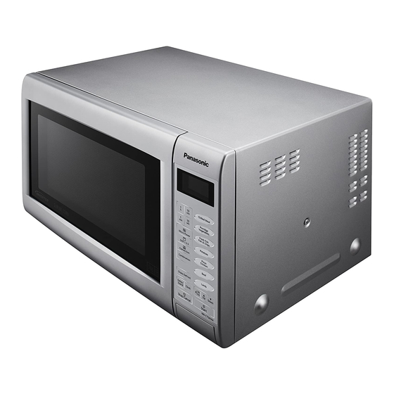
Page 1: Microwave Oven
ORDER NO.PAPMOSH1502012CE Microwave Oven NN-CT585S NN-CT565M NN-CT555W BPQ (U.K.) © Panasonic Appliances Microwave Oven (Shanghai) Co., Ltd. 2015. - Page 2 NN-CT585S / NN-CT565M / NN-CT555W...
- Page 3 NN-CT585S / NN-CT565M / NN-CT555W...
-
Page 4: Table Of Contents
4.5. Door assembly 8.6. PACKING AND ACCESSORIES 4.6. Turntable motor 9 DIGITAL PROGRAMMER CIRCUIT 4.7. Quartz heater 9.1. SCHEMATIC DIAGRAM (NN-CT585S) (D.P.C. (AU) BOARD) 4.8. Convection fan assembly 4.9. Inverter power supply 9.2. SCHEMATIC DIAGRAM (NN-CT585S) (D.P.C. (DU) 5 COMPONENT TEST PROCEDURE BOARD) 9.3. -
Page 5: Description Of Operating Sequence
NN-CT585S / NN-CT565M / NN-CT555W 2 DESCRIPTION OF OPERATING SEQUENCE 2.1. Variable power cooking 2.4. Thermistor control The thermistor which fixed on magnetron detects magnetron temperature and make power down when the temperature High Voltage Inverter Power Supply (U) controls output power becomes abnormal high. -
Page 6: Cautions To Be Observed When Troubleshooting
NN-CT585S / NN-CT565M / NN-CT555W 3 CAUTIONS TO BE OBSERVED WHEN TROUBLESHOOTING Unlike many other appliances, the microwave oven is a high voltage, high current device. It is free from danger in ordinary use, though extreme care should be taken during repair. -
Page 7: Part Replacement
NN-CT585S / NN-CT565M / NN-CT555W 3.6. Verification after repair Discharging the high voltage capacitors WARNING 1. After repair or replacement of parts, make sure that the There is high voltage present with high current capabilities screws of the oven, etc. are neither loosen or missing. -
Page 8: Disassembly And Parts Replacement Procedure
NN-CT585S / NN-CT565M / NN-CT555W 4 DISASSEMBLY AND PARTS REPLACEMENT PROCEDURE 4.1. Magnetron 7. Remove another 2 screws holding convection fan motor bracket on the top plate of the oven. 1. Discharge high voltage charge. 2. Disconnect 1 grounding connector. -
Page 9: Digital Programmer Circuit (D.p.c)
NN-CT585S / NN-CT565M / NN-CT555W 4.2. Digital programmer circuit 4. Remove door opening lever. (D.P.C) NOTE: Be sure to ground any static electric charge built up on your body before handling the D.P.C. 1. Disconnect all connectors from D.P.C board DU. -
Page 10: Low Voltage Transformer And/Or Power Relays (Ry1)
NN-CT585S / NN-CT565M / NN-CT555W 4.3. Low voltage transformer 4.4. Fan motor and/or power relays (RY1) 1. Disconnect 2 lead wires from fan motor terminals. 2. Remove 1 screw at location on oven attaching orifice NOTE: assembly. Be sure to ground any static electric charge built up on 3. -
Page 11: Door Assembly
NN-CT585S / NN-CT565M / NN-CT555W 4.5. Door assembly 4.6. Turntable motor 1. Remove door C from door E by carefully pulling outward, 1. Remove the motor cover by breaking off at the 8 spots starting from upper right hand corner using a flat blade indicated by arrows with a cutter or the like. -
Page 12: Quartz Heater
NN-CT585S / NN-CT565M / NN-CT555W 4.7. Quartz heater 1. Disconnect lead wires from heater terminals. 2. Remove heater fixing plate. 3. Remove 2 screws holding heater link on the heater terminals. 4. Remove 2 screws holding heater mounting plate. 5. Remove the heater by pulling it out. -
Page 13: Inverter Power Supply
NN-CT585S / NN-CT565M / NN-CT555W 4.9. Inverter power supply 6. Remove 1 screw holding Inverter bracket on the bottom of the base. CAUTIONS 1. Always leave the grounding plate in place. 2. Always securely tighten the ground screw through the bottom of the chassis (base). - Page 14 NN-CT585S / NN-CT565M / NN-CT555W 9. Remove 1 screw holding grounding plate to H.V. Inverter. 10. Seperate H.V. Inverter from Inverter bracket by freeing 3 catch hooks on the Inverter bracket.
-
Page 15: Component Test Procedure
NN-CT585S / NN-CT565M / NN-CT555W 5 COMPONENT TEST PROCEDURE WARNING 5.3. Magnetron 1. High voltage is present at the output terminals of the High Voltage Inverter (U) including aluminum heat sink during any cook cycle. Continuity checks can only indicate an open filament or a 2. -
Page 16: Inverter Power Supply (U)
NN-CT585S / NN-CT565M / NN-CT555W 5.4. Inverter power supply (U) 5. Program oven at High power for 1 minute and press [Start] DO NOT try to REPAIR H.V. Inverter power supply pad. (U).Replace complete H.V. Inverter(U) Unit. a. After approximately 3 seconds, oven stops operating. -
Page 17: Measurements And Adjustments
NN-CT585S / NN-CT565M / NN-CT555W 6 MEASUREMENTS AND ADJUSTMENTS 6.1. Adjustment of primary latch 6.2. Measurement of microwave switch, secondary latch switch output and short switch. The output power of the magnetron can be determined by performing IEC standard test procedures. However,due to the 1. -
Page 18: Troubleshooting Guide
NN-CT585S / NN-CT565M / NN-CT555W 7 TROUBLESHOOTING GUIDE DANGER: HIGH VOLTAGES 1. DO NOT RE-ADJUST PRESET CONTROL on the H.V.Inverter (U). It is very dangerous to repair or adjust without proper test equipment because this circuit generates very large current and high voltage. Operating a misaligned inverter circuit is dangerous. -
Page 19: Troubleshooting) Other Problems
NN-CT585S / NN-CT565M / NN-CT555W 7.2. (Troubleshooting) Other problems SYMPTOM CAUSE CORRECTIONS 1. Oven is dead. 1. Open or loose lead wire harness Fuse is OK. 2. Open thermal cutout / thermistor Check thermal cutout is defective. No display and no operation at all. -
Page 20: Troubleshooting Of Inverter Circuit (U) And Magnetron
NN-CT585S / NN-CT565M / NN-CT555W 7.3. Troubleshooting of inverter circuit (U) and magnetron This oven is programmed with a self diagnostics failure code system which will help for troubleshooting. H95, H97, H98 and H99 are the provided failure codes to indicate magnetron and inverter circuit problem areas. This section explains failure codes of H95, H97, H98 and H99. -
Page 21: Simple Way Of H.v. Inverter/Magnetron Troubleshooting
NN-CT585S / NN-CT565M / NN-CT555W 7.4. Simple way of H.V. Inverter/magnetron troubleshooting Purpose: Simple way (3/23 seconds rule) of identifying whether it’s Magnetron, Inverter, or others. Set-up: The unit under question is connected through the Ammeter as shown below. Procedure: Follow the matrix table below to identify the problem source. -
Page 22: Inverter Main Parts List (Z606Ybh20Gp)
NN-CT585S / NN-CT565M / NN-CT555W 7.6. H.V. INVERTER MAIN PARTS LIST (Z606YBH20GP) Ref. No. Part No. Part Name & Description Pcs/Set Remarks Q701 Z1JAEV000003 IGBT C701 ZCWHC3B104JA FILM CAPACITOR 0.1µF,1000VDC C702 ZCWF4305N851 FILM CAPACITOR 3µF,250VDC DB701 Z0FBBQ000006 RECTIFIER BRIDGE L701...