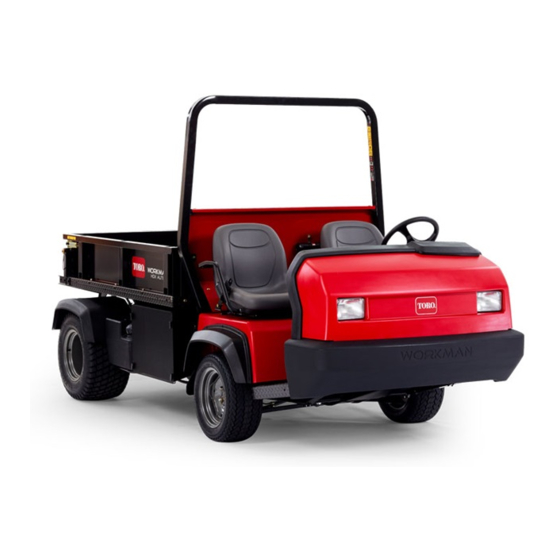
Toro Workman HD 07369 Operator's Manual
Utility vehicle with bed
Hide thumbs
Also See for Workman HD 07369:
- Operator's manual (52 pages) ,
- Operator's manual (56 pages)

Related Manuals for Toro Workman HD 07369


Summary of Contents for Toro Workman HD 07369
- Page 1 Form No. 3401-134 Rev A Workman ® HD Utility Vehicle with Model No. 07369—Serial No. 316000001 and Up *3401-134* A Register at www.Toro.com. Original Instructions (EN)
- Page 2 This manual uses 2 other words to highlight information. Important calls attention to special mechanical information You may contact Toro directly at www.Toro.com for product and Note emphasizes general information worthy of special and accessory information, help finding a dealer, or to register attention.
-
Page 3: Table Of Contents
Contents Fuel System Maintenance ...........41 Replacing the Fuel Filter..........41 Inspecting the Fuel Lines and Connections....41 Safety ................4 Electrical System Maintenance ........41 Safe Operating Practices........... 4 Servicing the Fuses ..........41 Safety and Instructional Decals ......... 8 Jump-Starting the Machine ........42 Setup ................14 Servicing the Battery..........43 1 Checking the Fluid Levels ........14... -
Page 4: Safety
Safety • Always wear substantial shoes. Do not wear loose-fitting clothing, tie back long hair, and do not wear jewelry. Improper use or maintenance by the operator or owner can • Wearing safety glasses, safety shoes, and long pants are result in injury. - Page 5 • If fuel is spilled on clothing, change clothing immediately. caution when handling off-center loads that cannot be centered. Keep loads balanced and secure to • Never overfill the fuel tank. Replace the fuel cap and prevent them from shifting. tighten it securely.
- Page 6 • Braking Heavy loads affect stability. Reduce the weight of the load and your ground speed when operating on hills or if • Slow down the machine before you approach an obstacle. the load has a high center of gravity. Secure the load to This gives you extra time to stop or turn away.
- Page 7 Do not overspeed the engine by changing the governor caution on slopes. settings. The maximum engine speed is 3,650 rpm. To ensure safety and accuracy, have an Authorized Toro • Be aware that heavy loads increase your stopping distance Distributor check the maximum engine speed with a and reduce your ability to turn quickly without tipping tachometer.
-
Page 8: Safety And Instructional Decals
Safety and Instructional Decals Safety decals and instructions are easily visible to the operator and are located near any area of potential danger. Replace any decal that is damaged or lost. 93-9850 1. Do not repair or revise—read the Operator's Manual. 93-9852 1. - Page 9 106-2353 115-7741 1. Electrical power point 1. Read the Operator’s Manual before servicing transmission fluid. 115-2047 1. Warning—do not touch the hot surface. Battery Symbols Some or all of these symbols are on your battery. 1. Explosion hazard 6. Keep bystanders a safe distance from the battery.
- Page 10 106-7767 1. Warning—read the Operator's Manual; avoid tipping the machine; wear the seat belt; lean away from the direction the machine is tipping. 115-7723 1. Warning—the hydraulic oil pressure is 124 bar (1,800 psi). 2. Coupler A 3. Coupler B...
- Page 11 115-2282 1. Warning—read the Operator's Manual. 2. Warning—stay away from moving parts, keep all guards and shields in place. 3. Crushing/dismemberment hazard of bystanders—keep bystanders a safe distance from the vehicle, do not carry passengers in the cargo bed, keep arms and legs inside of the vehicle at all times, and use seat belts and handholds. 115-2281 1.
- Page 12 115-7814 121-9776 1. Warning—read the Operator’s Manual and receive proper 4. Warning—engage the parking brake, stop the engine, and training before operating the machine. remove the key from the ignition before walking away from the machine. 2. Warning—wear hearing protection. 5.
- Page 13 106-2377 1. Locked 8. Warning—read the Operator's Manual. 2. Differential lock 9. Entanglement hazard, shaft—keep bystander's a safe distance from the vehicle. 3. Unlocked 10. Retract hydraulics 4. Hydraulic lock 11. Extend hydraulics 5. Engage 12. Transmission—high speed 6. Power take-off (PTO) 13.
-
Page 14: Setup
Setup Loose Parts Use the chart below to verify that all parts have been shipped. Procedure Description Qty. Check the engine oil, the – No parts required transaxle/hydraulic fluid, and the brake-fluid levels. ROPS frame Mount the Rollover-Protection System (ROPS). Flange-head bolt (1/2 x 1-1/4 inches) Media and Additional Parts Description... -
Page 15: Product Overview
Product Overview Controls Note: Determine the left and right sides of the machine from the normal operating position. Accelerator Pedal The accelerator pedal (Figure 4) gives the operator the ability to vary the engine and ground speed of the machine when the transmission is in gear. -
Page 16: Parking Brake
Gear-Shift Lever Fully press the clutch pedal and move the shift lever (Figure 6) into the desired gear selection. A diagram of the shift pattern is shown inFigure Figure 6 Figure 5 1. Gear-shift lever 4. Hydraulic-lift lock 2. Parking brake 5. -
Page 17: Hour Meter
Use the ignition switch (Figure 7) to start and shut off the contact your local Toro distributor for assistance. engine. It has 3 positions: O , and S . Rotate the... -
Page 18: Fuel Gauge
Charge Indicator Passenger Hand Hold Illuminates when the battery is being discharged. If the light The passenger hand hold is located on the dashboard (Figure illuminates during operation, stop the machine, turn off the engine, and check for possible causes (Figure Important: If the alternator belt is loose or broken, do not operate the machine until adjustment or repair is... -
Page 19: Specifications
Contact your Authorized Service Dealer or Driving the machine with the cargo box raised may Distributor or go to www.Toro.com for a list of all approved attachments and accessories. cause the machine to tip or roll easier. The box structure may become damaged if you operate the machine with the box raised. -
Page 20: Checking The Engine-Oil Level
Figure 10 1. Cargo-box lever Lowering the Box WARNING Figure 11 The weight of the box may be heavy. Hands or other body parts could be crushed. 1. Latch handle 3. Latch pin 2. Latch gate Keep hands and other body parts clear when lowering the box. -
Page 21: Adding Fuel
oil level to the Full mark. Do not overfill the engine with oil. If the oil level is between the Full and Add marks, no additional oil is required. 1. Position the machine on a level surface. 2. Remove the dipstick and wipe it with a clean rag (Figure 13). - Page 22 DANGER WARNING In certain conditions, fuel is extremely flammable Fuel is harmful or fatal if swallowed. Long-term and highly explosive. A fire or explosion from fuel exposure to vapors can cause serious injury and can burn you and others and can damage property. illness.
-
Page 23: Checking The Transaxle/Hydraulic-Fluid Level
Checking the Torque of the 3. Fill the tank to about one inch below the top of the tank, (bottom of the filler neck), then install the cap. Wheel Nuts Note: Do not overfill the fuel tank. Service Interval: After the first 2 hours 4. -
Page 24: Checking The Brake-Fluid Level
Checking the Brake-Fluid Level Service Interval: Before each use or daily—Check the brake-fluid level. (Check the level before the engine is first started and every 8 hours or daily, thereafter.) Every 1,000 hours/Every 2 years (whichever comes first)—Change the brake fluid. Brake fluid type: DOT 3 brake fluid The brake-fluid reservoir is located under the dash. -
Page 25: Driving The Machine
Driving the Machine • After starting a cold engine, let it warm up for about 15 seconds before shifting into gear. 1. Release the parking brake. • Avoid racing the engine. 2. Fully press the clutch pedal. • To ensure optimum performance of the brake system, 3. -
Page 26: Ensuring Passenger Safety
Verifying the Hydraulic-Lift Lever Interlock Switch 1. Sit on the operator’s seat and engage the parking brake. 2. Move the shift lever to the N position and EUTRAL ensure that the hydraulic-lift lever is in the center position. 3. Press clutch pedal. 4. -
Page 27: Ensuring Proper Braking
Ensuring Proper Braking Operating on Hills It is good practice to slow down before you get near an WARNING obstacle. This gives you extra time to stop or turn away. Hitting an obstacle can damage the machine and its contents. Tipping or rolling the machine on a hill could cause More important, it can injure you and your passenger. -
Page 28: Loading And Dumping
Loading and Dumping loads so that they do not shift. Never dump the load while the machine is sideways on the hill. The weight and position of the cargo and passenger can Heavy loads increase stopping distance and reduce your change the machine center of gravity and machine handling. -
Page 29: Transporting The Machine
In case of an emergency, the machine can be towed for a sure that the machine is secured to the trailer. Refer to Figure short distance. However, Toro does not recommend this as Figure 24 for the location of the tie-down points. -
Page 30: Using The Hydraulic Control
Using the Hydraulic Control • (Quick Coupler “B”) Position OWER This position lowers the bed, rear hitch attachment, or The hydraulic control supplies hydraulic power from the applies pressure to quick coupler B. This also allows machine pump whenever the engine runs. The power can be hydraulic fluid to return from quick coupler A to flow used through the quick couplers at the rear of the machine. - Page 31 Disconnecting the Quick Couplers Note: With both the vehicle and attachment turned off, move the lift lever back and forth to remove the system pressure and ease the disconnection of the quick couplers. 1. Pull back the locking ring on the coupler. 2.
-
Page 32: Maintenance
Maintenance Determine the left and right sides of the machine from the normal operating position. CAUTION Only qualified and authorized personnel should maintain, repair, adjust, or inspect the machine. Avoid fire hazards and have fire protection equipment present in the work area. Do not use an open flame to check level or leakage of fuel, battery electrolyte, or coolant. -
Page 33: Service-Interval Chart
Maintenance Service Maintenance Procedure Interval • Torque the front and rear wheel nuts. • Inspect opening on filter. • Check the adjustment of the shift cables. • Check the adjustment of the high–low cable. • Check the adjustment of the differential-lock cable. •... -
Page 34: Premaintenance Procedures
• Construction work • After extended operation in mud, sand, water, or similar dirty conditions, have your brakes inspected and cleaned as soon as possible. This prevents any abrasive material from causing excessive wear. Premaintenance Procedures Many of the subjects covered in this maintenance section require raising and lowering the bed. -
Page 35: Removing The Full Bed
Removing the Full Bed Installing the Full Bed 1. Start the engine, engage the hydraulic-lift lever, and Note: If the bed sides will be installed on the flat bed, it is lower the bed until the cylinders are loose in the slots. easier to install them before installing the bed on the machine. -
Page 36: Raising The Machine
Raising the Machine DANGER A machine on a jack may be unstable and slip off of the jack, injuring anyone beneath it. • Do not start the machine while the machine is on a jack. • Always remove the key from the switch before getting off the machine. -
Page 37: Removing The Hood
Installing the Hood 1. Connect the lights. 2. Insert the top mounting tabs into the frame slots. 3. Insert the lower mounting tabs into the frame slots. 4. Ensure that the hood is fully engaged in the top, sides and bottom grooves. Figure 33 1. -
Page 38: Lubrication
Lubrication Greasing Bearings and Bushings Service Interval: Every 100 hours (Lubricate more frequently in heavy duty applications) The machine has grease fittings that must be lubricated regularly with No. 2 lithium grease. The grease-fitting locations and quantities are as follows: •... -
Page 39: Engine Maintenance
Engine Maintenance Inspecting the Carbon Canister Air Filter Service Interval: After the first 50 hours Every 200 hours 1. Locate the air filter on the bottom of the carbon canister (Figure 39). Figure 40 1. Knob and O-ring 5. Breather seal 2. -
Page 40: Changing The Engine Oil And Filter
Changing the Engine Oil and Note: Do not overtighten. Filter 7. Add the specified oil to the crankcase; refer to Checking the Engine-Oil Level (page 20). Service Interval: After the first 50 hours Every 100 hours Replacing the Spark Plugs Engine-oil quantity: 1.9 L (2 US qt) (with a filter) Service Interval: Every 400 hours Engine-oil type: Detergent engine oil API SJ or higher... -
Page 41: Fuel System Maintenance
Fuel System Electrical System Maintenance Maintenance Replacing the Fuel Filter Servicing the Fuses Service Interval: Every 400 hours The fuses for the electrical system are located under the center of the dash panel (Figure 45 Figure 46). 1. Raise the bed (if equipped), and place the safety support on the extended-lift cylinder to hold up the bed. -
Page 42: Jump-Starting The Machine
Jump-Starting the Machine Note: Do not connect the other end of the jumper cable to the negative post of the discharged battery. Connect the jumper cable to the engine or frame. Do WARNING not connect the jumper cable to the fuel system. Jump-starting can be dangerous. -
Page 43: Servicing The Battery
Servicing the Battery Drive System Maintenance Service Interval: Every 50 hours—Check the battery-fluid level (every 30 days if in storage). Every 50 hours—Check the battery-cable connections. Adjusting the Shift Cables WARNING Service Interval: After the first 10 hours CALIFORNIA Every 200 hours Proposition 65 Warning 1. -
Page 44: Adjusting Differential-Lock Cable
Adjusting Differential-Lock Cable Service Interval: Every 200 hours 1. Move the differential-lock lever to the O position. 2. Loosen the jam nuts securing the differential-lock cable to the bracket on the transaxle (Figure 50). Figure 51 1. Under-inflated tire Figure 52 is an example of tire wear caused by over inflation. -
Page 45: Cooling System Maintenance
Cooling System Maintenance Removing Debris from the Engine-Cooling System Service Interval: Every 100 hours—Remove the debris from the engine-cooling system (Clean more Figure 53 frequently in dirty conditions). 1. Front of the machine 3. Center to center distance To ensure proper cooling, clean the blower housing and 2. -
Page 46: Brake Maintenance
Brake Maintenance Adjusting the Brake Pedal Service Interval: Every 200 hours Adjusting the Parking Brake Note: Remove the font hood to make the adjustment procedure easier. Service Interval: After the first 10 hours 1. Remove the cotter pin and clevis pin securing the Every 200 hours master-cylinder yoke to the brake-pedal pivot (Figure... -
Page 47: Belt Maintenance
Belt Maintenance Checking the Pump-Belt Tension Service Interval: After the first 10 hours Every 200 hours Check the pump belt for wear, cracking, or improper tension. Check the tension by pressing belt at mid span between the crankshaft and pump pulleys with 10 kg (22 lb) of force. A new belt should deflect 12 to 15 mm (0.48 to 0.58 inch) A used belt should deflect 14 to 16.5 mm (0.55 to 0.65 inch). -
Page 48: Controls System Maintenance
Controls System 4. Tighten the jam nuts after you have attained the adjustment. Maintenance 5. Check the 9.2 to 9.8 cm (3-5/8 to 3-7/8 inches) dimension after the jam nuts have been tightened to ensure proper adjustment. Adjusting the Clutch Pedal Note: Adjust again if it is necessary. -
Page 49: Adjusting The Choke
Figure 64 1. 2.54 to 6.35 mm (0.100 to 0.250 inch) clearance Note: The engine must not be running and the return spring must be attached. Figure 63 1. Return spring 5. Governor spring Adjusting the Choke 2. Engine-governor arm 6. -
Page 50: Hydraulic System Maintenance
Hydraulic System Maintenance Changing the Hydraulic Fluid and Cleaning the Strainer Service Interval: Every 800 hours Hydraulic-fluid capacity: 7 L (7.5 US qt) Hydraulic-fluid type: Dexron III ATF 1. Position the machine on a level surface, shut off the engine, engage the parking brake, and remove the key from the ignition switch. -
Page 51: Raising The Cargo Box In An Emergency
You will need 2 hydraulic hoses, each with a male and female quick coupler, that fit the vehicle couplers, to perform this operation. 1. Back another machine up to the rear of the disabled machine. Important: The machine hydraulic system uses Dexron III ATF. -
Page 52: Cleaning
Cleaning 5. On the other machine, connect the 2 hoses to the coupler still in the coupler bracket (connect the top hose to the top coupler and the bottom hose to the Washing the Machine bottom coupler) (Figure 70). 6. Cap the unused fittings. Wash the machine as needed. -
Page 53: Storage
Storage 10. With the spark plugs removed from the engine, pour 2 tablespoons of engine oil into the spark-plug hole. 1. Position the machine on a level surface, set the parking 11. Use the starter to crank the engine and distribute the brake, shut off the engine, and remove the ignition key. -
Page 54: Troubleshooting
Troubleshooting Problem Possible Cause Corrective Action The engine does not start, starts hard, or 1. The hydraulic lever is locked in forward 1. Move the hydraulic lever out of forward fails to keep running. position position. 2. The fuel tank is empty. 2. - Page 55 Notes:...
- Page 56 Countries Other than the United States or Canada Customers who have purchased Toro products exported from the United States or Canada should contact their Toro Distributor (Dealer) to obtain guarantee policies for your country, province, or state. If for any reason you are dissatisfied with your Distributor's service or have difficulty obtaining guarantee information, contact the Toro importer.