HP 260 G2 DM Hardware Reference Manual
Desktop mini
Hide thumbs
Also See for 260 G2 DM:
- Maintenance and service manual (114 pages) ,
- Product end-of-life disassembly instructions (15 pages)
Table of Contents
Advertisement
Advertisement
Table of Contents

Related Manuals for HP 260 G2 DM


Summary of Contents for HP 260 G2 DM
- Page 1 Hardware Reference Guide HP 260 G2 DM Business PC...
- Page 2 HP products and services are set forth in the bound by the terms of the HP End User License express warranty statements accompanying Agreement (EULA). If you do not accept these such products and services.
-
Page 3: About This Book
About This Book This guide provides basic information for upgrading the HP Desktop Mini Business PC. WARNING! Indicates a hazardous situation that, if not avoided, could result in death or serious injury. CAUTION: Indicates a hazardous situation that, if not avoided, could result in minor or moderate injury. - Page 4 About This Book...
-
Page 5: Table Of Contents
Table of contents 1 Product features ............................1 Standard configuration features ........................... 1 Front panel components ............................2 Rear panel components ............................2 Serial number location ............................3 2 Hardware upgrades ............................4 Serviceability features ............................4 Warnings and cautions ............................4 Connecting the power cord ............................ - Page 6 Contacting support .............................. 26 Index ................................27...
-
Page 7: Product Features
Product features Standard configuration features Features may vary depending on the model. For a complete listing of the hardware and software installed in the computer, run the diagnostic utility (included on some computer models only). NOTE: This computer model can be used in a tower orientation or a desktop orientation. The tower stand is sold separately. -
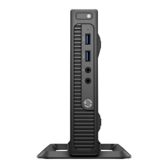
Page 8: Front Panel Components
Front panel components Drive configuration may vary by model. Front panel components Audio-out (headphone) jack Hard drive activity light Audio-in (microphone) jack Power button USB 3.0 ports NOTE: The Power On light is normally white when the power is on. If it is flashing red, there is a problem with the computer and it is displaying a diagnostic code. -
Page 9: Serial Number Location
Serial number location Each computer has a unique serial number and a product ID number that are located on the exterior of the computer. Keep these numbers available for use when contacting customer service for assistance. Serial number location... -
Page 10: Hardware Upgrades
To reduce the risk of serious injury, read the Safety & Comfort Guide. It describes proper workstation, setup, posture, and health and work habits for computer users, and provides important electrical and mechanical safety information. This guide is located on the Web at http://www.hp.com/ergo. WARNING! Energized and moving parts inside. -
Page 11: Connecting The Power Cord
Connecting the power cord When connecting the power supply, it is important to follow the steps below to ensure the power supply cord does not pull free from the computer. Plug the female end of the power cord into the AC adapter (1). Connect the other end of the power cord to an AC outlet (2). -
Page 12: Removing The Computer Access Panel
Removing the computer access panel To access internal components, you must remove the access panel: Remove/disengage any security devices that prohibit opening the computer. Remove all removable media, such as a USB flash drive, from the computer. Turn off the computer properly through the operating system, and turn off any external devices. Disconnect the power cord from the AC outlet and disconnect any external devices. -
Page 13: Replacing The Computer Access Panel
Replacing the computer access panel Place the access panel on the computer and slide it back (1), and then install the screw (2) to secure the panel in place. Replacing the computer access panel... -
Page 14: Changing From Desktop To Tower Configuration
Changing from desktop to tower configuration The computer can be used in a tower orientation with an optional tower stand that can be purchased from HP. Remove all removable media, such as a USB flash drive, from the computer. Turn off the computer properly through the operating system, and turn off any external devices. -
Page 15: Removing And Replacing A Hard Drive
Removing and replacing a hard drive IMPORTANT: Before you remove the old hard drive, be sure to back up the data from the old hard drive so that you can transfer the data to the new hard drive. Remove/disengage any security devices that prohibit opening the computer. Remove all removable media, such as a USB flash drive, from the computer. - Page 16 Remove the silver and blue isolation mounting guide screws from the sides of the old hard drive. Install the silver and blue isolation mounting guide screws in the sides of the new hard drive. Chapter 2 Hardware upgrades...
- Page 17 Plug the combined power and data cable into the hard drive (1). Align the guide screws with the slots on the chassis drive cage, press the hard drive down into the bay, and then slide the hard drive forward (2) until it stops and locks into place.
-
Page 18: Installing Additional Memory
Installing additional memory The computer comes with at least one preinstalled double data rate 4 synchronous dynamic random access memory (DDR4-SDRAM) small outline dual inline memory module (SODIMM). There are two memory sockets on the system board that can be populated with up to 32 GB of memory. DDR4-SDRAM SODIMMs For proper system operation, the SODIMMs must be: industry-standard 288-pin... -
Page 19: Populating Sodimm Sockets
Populating SODIMM sockets There are two SODIMM sockets on the system board, with one socket per channel. The sockets are labeled DIMM1 and DIMM2. The DIMM1 socket operates in memory channel B. The DIMM2 socket operates in memory channel A. Item Description System Board Label... -
Page 20: Installing Sodimms
Installing SODIMMs IMPORTANT: You must disconnect the power cord and wait approximately 30 seconds for the power to drain before adding or removing memory modules. Regardless of the power-on state, voltage is always supplied to the memory modules as long as the computer is plugged into an active AC outlet. Adding or removing memory modules while voltage is present may cause irreparable damage to the memory modules or system board. - Page 21 Slide the new SODIMM into the socket at approximately a 30° angle (1), and then press the SODIMM down (2) so that the latches lock it in place. NOTE: A memory module can be installed in only one way. Match the notch on the module with the tab on the memory socket.
-
Page 22: Replacing The Battery
The lifetime of the lithium battery can be extended by plugging the computer into a live AC outlet. The lithium battery is only used when the computer is NOT connected to AC power. HP encourages customers to recycle used electronic hardware, HP original print cartridges, and rechargeable batteries. For more information about recycling programs, go to http://www.hp.com/recycle. - Page 23 Locate the battery and battery holder on the system board. To release the battery from its holder, pull back the metal clamp that extends above one edge of the battery (1). When the battery pops up, lift it out of the holder (2). Replacing the battery...
-
Page 24: Installing An Optional Rear Port Cover
To insert the new battery, make sure the positive side of the battery is facing up and slide one edge of the replacement battery under the metal clamp that was pulled back when removing the old battery. Push the other edge down until the clamp on that side of the battery secures the battery in the holder. Replace the hard drive. -
Page 25: Installing A Security Lock
Installing a security lock The security locks displayed below and on the following pages can be used to secure the computer. Cable lock Padlock Installing a security lock... -
Page 26: Mounting The Computer
Remove four screws from the bottom side of the computer if they are installed. Using four 15 mm screws included in the mounting device kit, attach one side of the HP Quick Release to the computer as shown in the following illustration. - Page 27 Attach the other side of the HP Quick Release to the device to which you will mount the computer. Be sure the release lever points upward. Slide the side of the mounting device attached to the computer (1) over the other side of the mounting device (2) to mount the computer.
-
Page 28: Supported Mounting Options
Supported mounting options The following illustrations demonstrate some of the supported mounting options for the mounting bracket. On the back of a flat panel monitor ● On a wall ● Under a desk, allowing at least 2.5 cm (1 in) clearance ●... -
Page 29: Appendix A Electrostatic Discharge
● Use a portable field service kit with a folding static-dissipating work mat. ● If you do not have any of the suggested equipment for proper grounding, contact an HP authorized dealer, reseller, or service provider. NOTE: For more information on static electricity, contact an HP authorized dealer, reseller, or service provider. -
Page 30: Appendix B Computer Operating Guidelines, Routine Care And Shipping Preparation
Computer operating guidelines, routine care and shipping preparation Computer operating guidelines and routine care Follow these guidelines to properly set up and care for the computer and monitor: Keep the computer away from excessive moisture, direct sunlight, and extremes of heat and cold. ●... -
Page 31: Shipping Preparation
Shipping preparation Follow these suggestions when preparing to ship the computer: Back up the hard drive files to an external storage device. Be sure that the backup media is not exposed to electrical or magnetic impulses while stored or in transit. NOTE: The hard drive locks automatically when the system power is turned off. -
Page 32: Appendix C Accessibility
Accessibility HP designs, produces, and markets products and services that can be used by everyone, including people with disabilities, either on a stand-alone basis or with appropriate assistive devices. Supported assistive technologies HP products support a wide variety of operating system assistive technologies and can be configured to work with additional assistive technologies. - Page 33 6 hard drive 9 hard drive installation 9 security removal 9 cable lock 19 HP Quick Release 20 padlock 19 serial number location 3 shipping preparation 25 installation guidelines 4 supported mounting options 22 installing battery 16...