Table of Contents
Advertisement
Service Manual
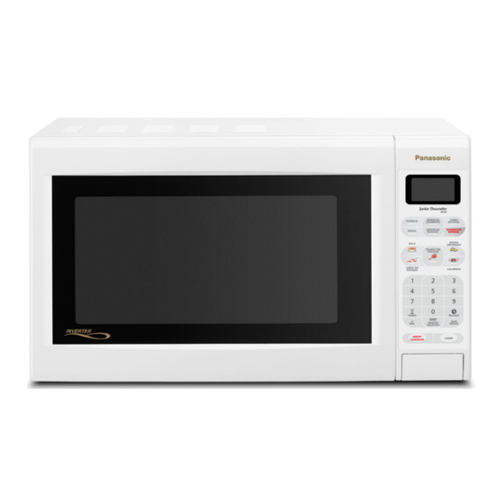
Microwave Oven
NN-G55 AR
Specifications
Power Source
Power requirement
Microwaves
Heater
Output (IEC 705-88)
Microwaves
Heater
Microwaves Frequency
Timer
Oven Cavity Dimensions
Weight
Outside Dimensions (H x W x D)
Color
Panasonic
Specifications are subject to change without prior notice or obligation.
ORDER DCS-SEP2005-003-MS
220V AC, 50 Hz
1,50KWh
1,17KWh
900 W
1.100 W
2.450 MHz
99 minutes and 99 seconds
27 liters
12 Kg
306 x 516 x 380 mm
White
©
2005 Panasonic da Amazônia S.A.
CS Division
Technical Support
Advertisement
Table of Contents
Troubleshooting

Related Manuals for Panasonic NN-G55 AR


Summary of Contents for Panasonic NN-G55 AR
-
Page 1: Microwave Oven
27 liters Weight 12 Kg Outside Dimensions (H x W x D) 306 x 516 x 380 mm Color White Specifications are subject to change without prior notice or obligation. © 2005 Panasonic da Amazônia S.A. Panasonic CS Division Technical Support... -
Page 2: Table Of Contents
NN-G55 AR ! WARNING This service information is designed for experienced repair technicians only and is not designed for use by the general public. It does not contain warnings or cautions to advise non-technical individuals of potential dangers in attempting to service a product. -
Page 3: Inverter Warning
NN-G55 AR INVERTER WARNING WARNING! DANGER OF HIGH VOLTAGE AND HIGH TEMPERATURE (HOT/LIVE) OF THE INVERTER POWER SUPPLY (U) This Inverter board looks like a regular PCB. However, this PCB drives the magnetron tube with extremely high voltage and high current. -
Page 4: Control Panel
NN-G55 AR CONTROL PANEL NN-G55 AR Tecla Cocción por Sensor Tecla Descongelación Turbo Tecla Selección de Potencia Tecla Dorador Manual Tecla Pochoclo Tecla Recalentamiento por Sensor Tecla Dorador Automático Tecla Tiempo (Tiempo de Espera/Instrucciones el visor) Teclas numéricas Tecla +1 Minuto Tecla Reloj (Reloj/Modo de (Ajuste Rápido) - Page 5 NN-G55 AR - 5 -...
- Page 6 NN-G55 AR - 6 -...
- Page 7 NN-G55 AR - 7 -...
- Page 8 NN-G55 AR - 8 -...
- Page 9 NN-G55 AR - 9 -...
-
Page 10: Schematic Diagram
NN-G55 AR SCHEMATIC DIAGRAM CAUTION ! HIGH VOLTAGE AREA NOTE : DOOR IS CLOSED AND UNIT IS NOT OPERATION MAGNETRON BROWNER MODELS ONLY THERMAL CUT OUT PRIMARY LATCH SWITCH CN702 CN703 E702 E701 AC 220V BROWNER 50 Hz SHORT SWITCH... -
Page 11: Description Of Operating Sequence
NN-G55 AR DESCRIPTION OF OPERATING SEQUENCE 1. Variable power cooking control 3. Inverter Turbo Defrost The digital programmer circuit controls the ON-OFF time When this Auto Control feature is selected and the Start of power relay B contacts in order to vary the output power Pad is tapped: of the microwave oven from “Low”... -
Page 12: Cautions To Be Observed When Troubleshooting
NN-G55 AR CAUTIONS TO BE OBSERVED WHEN TROUBLESHOOTING 3. When parts must be replaced, remove the power Unlike many other appliances, the microwave oven is high- plug from the outlet. voltage, high current equipment. Though it is free from danger in ordinary use, extreme care should be taken during repair. -
Page 13: Disassembly And Parts Replacement Procedure
NN-G55 AR DISASSEMBLY AND PARTS REPLACEMENT PROCEDURE • Magnetron • Low voltage transformer and/or power relays (RY1, RY2) 1. Discharge the high voltage capacitors, as mentioned and shown on page 11. NOTE: 2. Disconnect 2 high voltage lead wires from magnetron Be sure to ground any static electric charge built up on your filament terminals. - Page 14 NN-G55 AR • Door assembly • Steam Sensor Sensor air guide “C” Sensor air guide “B” Tabs Oriffice Door “A” Screw Door Key Tabs Oriffice Sensor Surface Door“A” Door Key Metal surface Door Key Spring Door “C” Door “E” (A) Remove door C from door E by carefully pulling outward 1.
-
Page 15: Component Test Procedure
NN-G55 AR COMPONENT TEST PROCEDURE CAUTION 4. Membrane key board (Membrane switch assembly) 1. High voltage is present at the high voltage terminal of the High Check continuity between switch terminals, by tapping an Voltage Inverter (U) including aluminum heat sink during any appropriate pad on the key board. -
Page 16: Procedure For Measuring Microwave Energy Leakage
NN-G55 AR PROCEDURE FOR MEASURING MICROWAVE ENERGY LEAKAGE 1. Equipment (2) Measurements with a fully assembled oven. *Electromagnatic radiation monitor After all components, including outer panel are fully *Glass thermometer 212 ºF or 100 ºC assembled, measure for radiation leakage around the... -
Page 17: Measurements And Adjustments
NN-G55 AR MEASUREMENTS AND ADJUSTMENTS • Magnetron Output Potency Test WARNING 1 - Puts on the tray 2 beackers with exactly 1 liter of water in each. * For continued protection against radiation hazard, replace only with identical replacement parts. -
Page 18: Troubleshooting Guide
NN-G55 AR TROUBLESHOOTING GUIDE CAUTION 1. Check grounding before checking for trouble. 2. Be careful of high voltage circuit. 3. Discharge high voltage capacitor. 4. When checking the continuity of the switches or the high voltage transformer,disconnect one lead wire from these parts and then check continuity with the AC plug removed. -
Page 19: Troubleshooting Of Inverter Circuit (U) And Magnetron
NN-G55 AR TROUBLESHOOTING OF INVERTER CIRCUIT (U) AND MAGNETRON This oven is programmed with a self diagnostics failure code system which will help for troubleshooting. H97, H98, and H99 are the provided failure codes to indicate magnetron and inverter circuit problem areas. This section explains failure codes of H97, H98, and H99. First, you must program the DPC by pressing Clock , Time , Start , Power Level . -
Page 20: Dpc Board Schematic Diagram
NN-G55 AR DPC BOARD SCHEMATIC DIAGRAM - 20 -... -
Page 21: Dpc Board Electrical Parts List
NN-G55 AR DPC BOARD ELECTRICAL PARTS LIST Ref. No. Part No. Part Name & Description Ref. No. Part No. Part Name & Description ASSEMBLED P.C.B. B3A0A22 WIRE JUMPER MBUPNN-G55AR ASSEMBLED PANEL P.C.B. B3A0A22 WIRE JUMPER BUZZER B3A0A22 WIRE JUMPER BZ310... - Page 22 NN-G55 AR Ref. No. Part No. Part Name & Description R491 MCR03EZHJ202 CARBON RESISTOR 2,00 kOhm 1/16 W R492 MCR03EZHJ103 CARBON RESISTOR 10,00 kOhm 1/16 W VZ340 NVZ6TLTB103 VARIABLE RESISTOR 10,00 kOhm 0,1W RELAY G5G-1A18VDC POWER RELAY 18 VDC 250 VAC...
-
Page 23: Inverter Pcb Schematic Diagram
NN-G55 AR INVERTER PCB SCHEMATIC DIAGRAM - 23 -... -
Page 24: Inverter Pcb Electrical Parts List
NN-G55 AR INVERTER PCB ELECTRICAL PARTS LIST REF. Nº Part Nº Part Name & Description REF. Nº Part Nº Part Name & Description ASSEMBLED P.C.B. J710 MCR03EZHJ000 CARBON RESISTOR 0,00 Ohm 1/16 W A606YM300GP INVERTER 220V ASSEMBLED P.C.B. J711 MCR03EZHJ000... - Page 25 NN-G55 AR REF. Nº Part Nº Part Name & Description REF. Nº Part Nº Part Name & Description R715 ERDS1TJ204T CARBON RESISTOR 200,00 kOhm 1/2 W R780 D0GB303ZA005 FILM RESISTOR 30,00 kOhm 1/16 W R717 ERDS2TJ510T CARBON RESISTOR 51,00 Ohm 1/4 W...
-
Page 26: Oven Exploded View
NN-G55 AR OVEN EXPLODED VIEW - 26 -... -
Page 27: Mechanical Parts List
NN-G55 AR MECHANICAL PARTS LIST REF. Nº Part Nº Part Name & Description FPR60C015AR TRIPOLAR AC CABLE F06025U00XN WIRE RACK CES14-10A CERAMIC FUSE 250V B62315G10XN FUSE HOLDER F06015Q00AP GLASS TRAY FPU50F006 CONNECTION WIRING KIT (*) FPD000001 WASHER F30205Q00AP DOOR HOOK J61414T00AP MICRO SWITCH “A”... -
Page 28: Door Assembly
NN-G55 AR DOOR ASSEMBLY Ref. Part Name & Description Part No. DOOR SCREEN “A” F31454T01AP DOOR “E” FPT30E001 DOOR KEY B30185Q00APA DOOR KEY SPRING FPD300020 DOOR SCREEN “B” F31465Q00BAP DOOR “A” B30015Q00HAP DOOR “C” B30855Q00AP - 28 -... -
Page 29: Escutcheon Base Assembly
NN-G55 AR ESCUTCHEON BASE ASSEMBLY Ref. Part Name & Description Part No. ESCUTCHEON SHEET FPU800303AR MEMBRANE SWITCH FPU800112I OPEN BUTTOM B80725Q00HAP SPRING FPD800002A ESCUTCHEON BASE B80345Q00HAP D.P. CIRCUIT MBUPNN-G55AR OPENER LEVER B82565Q00AP SCREW XTWP3+10C-RH - 29 -... - Page 30 Panasonic da Amazônia S.A. CS DIVISION - TECHNICAL SUPPORT Rod. Presidente Dutra, Km 155 São José dos Campos - SP...