
Related Manuals for HP Intelligent Power Distribution Unit


Summary of Contents for HP Intelligent Power Distribution Unit
- Page 1 HP Intelligent Power Distribution Unit User Guide Part Number 572153-002 July 2010 (Second Edition)
- Page 2 © Copyright 2010 Hewlett-Packard Development Company, L.P. The information contained herein is subject to change without notice. The only warranties for HP products and services are set forth in the express warranty statements accompanying such products and services. Nothing herein should be construed as constituting an additional warranty. HP shall not be liable for technical or editorial errors or omissions contained herein.
-
Page 3: Table Of Contents
Resetting the Intelligent Extension Bars ....................15 Extension Bar components ........................15 Resetting the iPDU ........................... 15 Installing the HP Intelligent Power Distribution Unit ................16 Installing the Core Unit ..........................16 Installing the Core Unit cord retention bracket ................... 16 Installing the 0U brackets ........................ - Page 4 Systems Insight Manager integration ..................... 75 Systems Insight Manager overview ......................75 Discovering the iPDU ..........................75 Configuring HP SIM to receive traps ......................76 Configuring the iPDU to send traps to HP SIM ..................... 77 Security considerations ........................ 78 Security considerations overview ....................... 78...
- Page 5 Flash update fails over a serial connection ....................89 Help files do not appear .......................... 89 HP Power Device Flash Utility does not install image.bin on a Pentium III ............89 HP SIM lists a discovered iPDU as Unmanaged in the System Type column ............. 89 Invalid IP address ............................
- Page 6 Federal Communications Commission notice ....................94 FCC rating label ..........................94 Class A equipment......................... 94 Class B equipment ......................... 94 Declaration of conformity for products marked with the FCC logo, United States only ........95 Modifications ............................95 Cables ..............................95 Canadian notice (Avis Canadien) ......................
-
Page 7: Overview
• Be sure that the load products connected to the HP Intelligent Power Distribution Unit (iPDU) are adjusted for, or otherwise capable of operation from the same line voltage supplying the iPDU. Failure to verify the voltage can lead to severe equipment damage. -
Page 8: Introduction
To download the latest versions of firmware and software, see the HP website (http://www.hp.com/go/rackandpower). * Intelligent power discovery requires HP ProLiant servers with iLO 2 v2.0 or newer firmware or iLO 3 v1.05 or newer firmware, combined with the Intelligent Extension Bar, PLC power cables, and HP ProLiant 94% efficiency common slot power supplies. -
Page 9: Typical Hardware Configuration
• Flexible mounting in 0U or 1U configurations, maximizing rack space (no additional parts are required for mounting) • Overcurrent and short-circuit protection for each output (UL-489-listed circuit breakers) • IEC-320 C19 outlets to power Extension Bars, Intelligent Extension Bars, or other IEC-320 C20 plug- compatible equipment •... -
Page 10: Web Interface Requirements
Up to six Extension Bars and Intelligent Extension Bars can be connected to provide 30 IEC-320 C13 outlets. Web interface requirements The following table lists the minimum requirements necessary to operate the web interface. CAUTION: It is highly recommended that browser access to the iPDU is isolated from outside access using a firewall or isolated network. -
Page 11: Component Identification And Operation
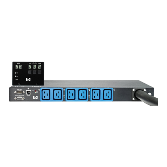
Component identification and operation iPDU components Callout Description Display Unit Core Unit Extension Bar Intelligent Extension Bar Component identification and operation 11... -
Page 12: Core Unit Components
Core Unit components Callout Description Circuit breaker for load segment 1 (phase A if 3 phase model) Circuit breaker for load segment 2 (phase B if 3 phase model) Circuit breaker for load segment 3 (phase C if 3 phase model) Circuit breaker for load segment 4 (phase A if 3 phase model) Circuit breaker for load segment 5 (phase B if 3 phase model) Circuit breaker for load segment 6 (phase C if 3 phase model) -
Page 13: Display Unit Components
Display Unit components Callout Description LED numeric display for amperage of load segments/Extension Bars and Intelligent Extension Bar outlets LED numeric display for PDU current selection (display corresponds to PDU current) LED numeric display for load segment/Extension Bar current selection (display corresponds to load segment/Extension Bar current) LED numeric display for Intelligent Extension Bar outlet current selection (display corresponds to Intelligent... -
Page 14: Intelligent Extension Bar Components
Press the Display Unit button that corresponds to the component. PDU—Scrolls through the PDUs in the iPDU installation LS—Scrolls through the iPDU load segments/Extension Bars in the iPDU installation Outlet—Scrolls through the Intelligent Extension Bar outlets in the iPDU installation The current selection displays in the LED numeric display above the corresponding button. -
Page 15: Resetting The Intelligent Extension Bars
Resetting the Intelligent Extension Bars To reset the Intelligent Extension Bars: Press the Reset button on the Intelligent Extension Bar you want to reset. The Reset button is located next to the input power cord. Wait for the Intelligent Extension Bar to reboot. When you press the Reset button, power to the managed outlets is maintained. -
Page 16: Installing The Hp Intelligent Power Distribution Unit
Installing the Core Unit cord retention bracket The Core Unit cord retention bracket is shown for clarification in the following diagram, though installation of the Core Unit cord retention bracket is optional. Installing the 0U brackets Installing the HP Intelligent Power Distribution Unit 16... -
Page 17: Installing The 1U Brackets
(A) or the 1U brackets (B) on the Core Unit. Installing the 1U Core Unit in a square-hole rail NOTE: Use the M6 screws and cage nuts that shipped with the rack when installing in a square-holed rail. Installing the HP Intelligent Power Distribution Unit 17... - Page 18 Installing the 0U Core Unit in a square-hole rail NOTE: Use the M6 screws and cage nuts that shipped with the rack when installing in a square-holed rail. Installing the HP Intelligent Power Distribution Unit 18...
- Page 19 Installing the 0U Core Unit in a square- and round-hole rail NOTE: Use the sheet metal mounting screws that are included with this kit when installing in a square- and round-holed rail. Installing the HP Intelligent Power Distribution Unit 19...
-
Page 20: Installing The Display Unit
Connect the serial cable to the PDU serial connector on the Display Unit. Install the Display Unit on the inside of the rack door. Attach the provided screws through the holes on the perforated door. Installing the HP Intelligent Power Distribution Unit 20... - Page 21 Connect the serial cable to the serial connector on the Core Unit. Installing the HP Intelligent Power Distribution Unit 21...
-
Page 22: Installing The Intelligent Extension Bars
Installing the Intelligent Extension Bars Installing the HP Intelligent Power Distribution Unit 22... - Page 23 Installation of the cord retention bracket is optional. Installing the HP Intelligent Power Distribution Unit 23...
-
Page 24: Installing The Extension Bars Using A Single Configuration
Installing the Extension Bars using a single configuration The cord retention bracket (1) is shown for clarification in the following diagram, though installation of the cord retention bracket is optional. Installing the HP Intelligent Power Distribution Unit 24... - Page 25 Installing the HP Intelligent Power Distribution Unit 25...
-
Page 26: Installing The Extension Bars Using A Double Configuration
Installing the Extension Bars using a double configuration The cord retention brackets (1) are shown for clarification in the following diagram, though installation of the cord retention brackets is optional. Installing the HP Intelligent Power Distribution Unit 26... -
Page 27: Connecting The Ground Bonding Cable
The ground bonding screw is provided as an attachment point for conductors. Use a ground bonding cable if the rack contains any conductors for the purpose of functional grounding or bonding of ungrounded metal parts. Installing the HP Intelligent Power Distribution Unit 27... -
Page 28: Connecting The Ipdu To The Power Source
The AC branch circuit overcurrent protection should be sized according to the standard of the plug configuration on each model. The maximum overcurrent rating for each model is listed in "Connecting devices (on page 29)." Installing the HP Intelligent Power Distribution Unit 28... -
Page 29: Connecting Devices
* For 3 phase iPDUs, each phase is defined as follows: – Phase A—Load segment 1 and load segment 4 – Phase B—Load segment 2 and load segment 5 – Phase C—Load segment 3 and load segment 6 Installing the HP Intelligent Power Distribution Unit 29... - Page 30 Insight Control power management v6.2 will draw the servers in order based on this best practice so that only minimal arrangement is needed to place the servers in the actual U position in the rack. Installing the HP Intelligent Power Distribution Unit 30...
-
Page 31: Checking The Display Unit Led Indicator
Connecting the network cable Connect a standard Ethernet cable between the network connector on the Core Unit and a network jack. This connection is used to access the iPDU through telnet or the web interface. Installing the HP Intelligent Power Distribution Unit 31... -
Page 32: Connecting A Host Computer
Be sure that you have connected a serial cable to the Display Unit and the host computer with an open terminal emulation session. Press the Reset button on either the Display Unit or the Core Unit. Installing the HP Intelligent Power Distribution Unit 32... - Page 33 On the Service Menu, enter 1 at the prompt to select Module Configuration. The HP Intelligent PDU Main menu (on page 64) appears. Use the Main menu to configure the minimum settings required to access the iPDU remotely using telnet or the web interface. You can configure other settings using this menu in conjunction with a terminal emulation program or a telnet connection.
-
Page 34: Hp Intelligent Pdu Web Interface
Also, system values can be configured through the web interface and sent to the iPDU. NOTE: All status information and configuration parameters included on the HP Intelligent PDU web interface are available using the HP Intelligent PDU Service Menu (on page 62). Accessing the web interface CAUTION: It is highly recommended that browser access to the iPDU is isolated from outside access using a firewall or isolated network. -
Page 35: Signing In To The Web Interface
NOTE: Passwords are case-sensitive. Select the appropriate language in the Language dropdown box. Click Sign In. The HP Intelligent PDU web interface appears. -or- Click Clear to clear the credentials. For information regarding the interface, see "Navigating the web interface (on page 37)."... -
Page 36: Browser Security Alert
Click Next. The Certificate Store screen appears. Select Automatically select the certificate store based on the type of certificate, and then click Next. Click Finish. A message appears, asking for verification of the root store. Click Yes. HP Intelligent PDU web interface 36... -
Page 37: Establishing A Secure Session For Mozilla
Click either Accept this certificate permanently or Accept this certificate temporarily for this session. Click OK. NOTE: If using Firefox, you can manually import the file into the browser by clicking Edit>Preferences>Advanced>Security>View Certificates>Authorities>Import. Navigating the web interface The web interface is divided into three frames: HP Intelligent PDU web interface 37... -
Page 38: Home Tab
Main frame—Contains the various interface screens based on the menu option selected in the left navigation frame. Home tab Menu options listed under the Home tab include: • Overview menu (on page 39) • Alarms menu (on page 40) • Identification menu (on page 40) HP Intelligent PDU web interface 38... -
Page 39: Overview Menu
The load percent for the iPDU is displayed graphically on the left side of the screen. The color on the meter represents the total load of the iPDU. Color Status Green Normal Yellow Warning Critical Click Refresh Page to refresh the screen. Click Help to view online help. HP Intelligent PDU web interface 39... -
Page 40: Alarms Menu
Click Identification in the left navigation frame to display the Identification screen. This screen contains contact information and device information for the iPDU and device information for each load segment. NOTE: Load segment 1 always corresponds to the outlet closest to the Core Unit power cord. HP Intelligent PDU web interface 40... -
Page 41: Status Menu
Click Status in the left navigation frame to display the Status screen. This screen displays the status for the iPDU by load segment. NOTE: Load segment 1 always corresponds to the outlet closest to the Core Unit power cord. HP Intelligent PDU web interface 41... -
Page 42: Control Menu
Click Control in the left navigation frame to access the Control screen. This screen contains controls that enable you to issue manual commands. The Control screen contains the following: • Control tab (on page 43) • Management Processor tab (on page 45) HP Intelligent PDU web interface 42... - Page 43 Redundancy Status—Indicates the status of the redundant iPDU configuration, if applicable ( Informational, Normal, Warning, or Critical) • Redundancy Control—Includes a checkbox that allows you to enable and disable redundancy control for the outlet HP Intelligent PDU web interface 43...
- Page 44 Click Save Settings to save the information. Click Refresh Page to refresh the screen. Click Help to view online help. For more information about redundant PDU communication, see "Configuring redundancy management (on page 72)." HP Intelligent PDU web interface 44...
-
Page 45: Outlet Device Assignment Menu
This screen contains controls that enable you to record information for devices attached to the iPDU load segments and Intelligent Extension Bar outlets, if applicable. NOTE: Load segment 1 always corresponds to the outlet closest to the Core Unit power cord. HP Intelligent PDU web interface 45... -
Page 46: Logs Tab
Click Undo Changes to undo the changes. Click Help to view online help. Logs tab Menu options listed under the Logs tab include: • Event Log menu (on page 47) • Application Log menu (on page 48) HP Intelligent PDU web interface 46... -
Page 47: Event Log Menu
Click Open to view the log in a user-selected application. Click Save to save the log file (.csv) to your computer. • Click Clear Event Log to clear the log files. • Click Help to view online help. HP Intelligent PDU web interface 47... -
Page 48: Application Log Menu
On the Application Log screen: • Click Download Application Log to export the application log. The File Download screen appears. Click Open to view the log in a user-selected application. HP Intelligent PDU web interface 48... -
Page 49: Setup Tab
Enter the new password in the Password field. Enter the new password again in the Verify Password field. Do one of the following: Click Save Settings to save the new password. Click Undo Changes to undo the changes. HP Intelligent PDU web interface 49... -
Page 50: User Accounts Menu
To modify a user password: Enter the user's login name in the Sign In Name field. Change the password: Enter the new password in the Password field. Enter the new password again in the Verify Password field. HP Intelligent PDU web interface 50... -
Page 51: Network Menu
If you enabled NTP in step 5: Enter the IP address of the primary NTP server. Enter the IP address of the secondary NTP server. Select the time zone from the dropdown box. HP Intelligent PDU web interface 51... -
Page 52: Network Management Menu
Trap Receivers tab (on page 54) • SNMP Managers tab (on page 55) • Email Setup tab (on page 56) • Event Notifications tab (on page 57) • Remote Access tab (on page 58) HP Intelligent PDU web interface 52... - Page 53 Click Undo Changes to undo the changes. Click Help to view online help. After redundancy is configured, a hyperlink to the redundant iPDU appears. Click the hyperlink to view the web interface for the redundant iPDU. HP Intelligent PDU web interface 53...
- Page 54 Click Undo Changes to undo the changes. Click Help to view online help. Click Send Test Trap to send a test SNMP trap. At least one Trap Receiver must be configured and enabled to send a test trap. HP Intelligent PDU web interface 54...
- Page 55 SNMP Managers tab This screen contains controls that enable administrators to enter information for SNMP managers. SNMP managers are computers that use the HP Power MIB to request information from the iPDU. To configure SNMP managers: Enable the SNMP manager configuration for up to five servers.
- Page 56 Click Undo Changes to undo the changes. Click Help to view online help. Click Send Test Email to send a test email. At least one email address must be configured and enabled to send a test email. HP Intelligent PDU web interface 56...
- Page 57 SNMP traps are sent for that event. To enable all events, click the Email checkbox and the SNMP Trap checkbox at the top of each column. Do one of the following: Click Save Settings to save the information. Click Undo Changes to undo the changes. Click Help to view online help. HP Intelligent PDU web interface 57...
- Page 58 For more detailed information about uploading the SSL certificate, see "Installing a digital certificate and encryption key for SSL (on page 78)." Configure the telnet connection: Enable Telnet Port. Enter the port number to use telnet. The default port is 23. Configure the session management settings: HP Intelligent PDU web interface 58...
-
Page 59: Pdu Thresholds Menu
For redundant iPDUs, adjust the thresholds to one half of the default value or less to ensure appropriate load balancing. Do one of the following: Click Save Settings to save the information. Click Undo Changes to undo the changes. Click Refresh Page to refresh the screen. HP Intelligent PDU web interface 59... -
Page 60: Help Tab
Click About in the left navigation frame to display the About screen. This screen displays the hardware version, the firmware version, and the MAC address for the iPDU, as well as a link to the HP website. HP Intelligent PDU web interface 60... -
Page 61: Contents Menu
Click Contents in the left navigation frame to display the Contents screen. This screen provides a list of the links to help topics. Info & Updates menu Click Info & Updates in the left navigation frame to open the HP website. HP Intelligent PDU web interface 61... -
Page 62: Hp Intelligent Pdu Service Menu
HP Intelligent PDU Service Menu HP Intelligent PDU Service Menu overview The HP Intelligent PDU Service Menu provides an alternative, limited interface to the iPDU when the web interface is disabled or not preferred. The menu structure textually displays various measurements and warning and alarm messages from the iPDU. -
Page 63: Post
If any error is detected in the boot process, the Core Unit LED indicator illuminates or flashes (on page 87). Navigating the menus After you have successfully initiated a terminal emulation or telnet session, the HP Intelligent PDU Service Menu (on page 64) appears. •... -
Page 64: Service Menu
This menu only appears when accessing the iPDU using a terminal emulation program. Option number Submenu Description Module Configuration Opens the HP Intelligent PDU Main menu (on page 64) PDU LED Module Pass- Bypasses the Display Unit to allow for direct through... - Page 65 Configuration HTTP/HTTPS Previous Menu Returns to the previous menu File Transfer (FTP) submenu Option number Submenu Description Enable/Disable service Enables you to enable or disable FTP service Previous Menu Returns to the previous menu HP Intelligent PDU Service Menu 65...
- Page 66 Description SNMP Managers (NMS) Enables you to select an entry to configure the SNMP managers (computers that use the HP Power MIB to request information from the iPDU SNMP Traps Enables you to select an entry to configure the SNMP traps receiver...
-
Page 67: System Configuration Submenu
Enables you to reset all locked out sessions All Users Previous Menu Returns to the previous menu System Configuration submenu Option number Submenu Description Date/Time Configuration Enables you to configure the date and time Previous Menu Returns to the previous menu HP Intelligent PDU Service Menu 67... - Page 68 Enables you to configure the amount of time the clock should change for daylight saving time in your region Change Daylight Saving Enables you to configure the day and time Time Start that daylight saving should start HP Intelligent PDU Service Menu 68...
-
Page 69: User Accounts Submenu
Returns to the previous menu My Account submenu Option number Submenu Description Change User Name Enables you to change your login name Change Password Enables you to change your login password Previous Menu Returns to the previous menu HP Intelligent PDU Service Menu 69... -
Page 70: Spares
Spares Ordering spares To order a spare, visit the HP website (http://www.hp.com/buy/parts). To replace parts under warranty, contact an HP authorized service representative. Spare parts list Item Description Spare part number Display Unit 572211-001 Single phase, 24 A Core Unit NA/JPN... -
Page 71: Hardware Options
1.4 m (4.5 ft) PLC power cable* 573697-001 .76 m (2.5 ft) PLC power cable* 573695-001 3.7 m (12 ft) serial download cable* 590976-001 * not shown Hardware options For information on the supported hardware options, see the HP website (http://www.hp.com/go/rackandpower). Spares 71... -
Page 72: Configuring Redundancy Management
To enable the iPDUs to automatically group device outlets, you need: • An HP ProLiant server with iLO 2 v2.0 or newer firmware or iLO 3 v1.05 or newer firmware and HP ProLiant 94% efficiency common slot power supplies. •... -
Page 73: Managing Device Power Redundancy
Managing device power redundancy If you are using HP ProLiant servers with iLO 2 v2.0 or newer firmware or iLO 3 v1.05 or newer firmware and HP ProLiant 94% efficiency common slot power supplies with PLC power cables, devices are automatically grouped. -
Page 74: Alert Messages
Alert messages iPDU alarms The iPDU enables you to send an email notification or SNMP trap to specified recipients if a certain alert situation prevails. The following table lists information for all alarm messages. Alarm text Description Recommendation Display Communication The Display Unit can no longer Check the communication link. -
Page 75: Systems Insight Manager Integration
URL in the trap. This functionality enables administrators to easily launch the web interface of the iPDU in context. For example, if the iPDU detects an alarm condition, the iPDU can send a trap to HP SIM with an attached hyperlink that routes users directly to the Overview screen for the attached iPDU. -
Page 76: Configuring Hp Sim To Receive Traps
8008=Default Home Page, ,true,false, ,http 1311=Server Administrator, ,true,false, ,https 1234=HP iPDU, ,true,false, ,https The last entry allows HP SIM to detect the iPDU running on port 1234 and using HTTPS (Secure Socket Layer protocol). HP SIM services must be restarted to apply the change. -
Page 77: Configuring The Ipdu To Send Traps To Hp Sim
Click the Network Management menu. Add the HP SIM server as an SNMP trap recipient on the Trap Receivers tab (on page 54). Configure the iPDU to send alert notifications to HP SIM on the Event Notifications tab (on page 57). -
Page 78: Security Considerations
Security considerations Security considerations overview The iPDU implements strict security for two important reasons: • The iPDU manages devices that have the potential to perform operations that are sensitive and destructive. • The iPDU has browser accessibility. To better ensure the security of the iPDU and the devices it manages, consider the following topics in accordance with your organization's security policies and the environment in which the iPDU will operate. - Page 79 http://www.somacon.com/p41.php (http://www.somacon.com/p41.php) To create your own 512- or 1024-bit SSL certificate and key, you can use the command in the following example: openssl req -x509 -nodes -days 365 -newkey rsa:512 -md5 -keyout mycert.pem -out mycert.pem -text The mycert.pem file includes both a certificate and an encrypted key. NOTE: •...
-
Page 80: Optional Power Monitoring Using Snmp
Using the SNMP Managers tab (on page 55), configure the third-party SNMP manager to monitor the iPDU. Using the third-party SNMP manager software, configure the iPDU information to be monitored by the SNMP manager. The HP Power MIB (CPQPOWER.MIB) can be downloaded from the HP website (http://www.hp.com/go/rackandpower). Optional power monitoring using SNMP 80... -
Page 81: Updating The Firmware
Updating the firmware Updating the firmware overview The HP Power Device Flash Utility is a universal tool used to flash firmware (image.bin) or replicate the configuration settings (config.bin) for the iPDU. The HP Power Device Flash Utility supports two different transfer modes: •... -
Page 82: Ftp Flash Mode
Press any key in 5 seconds to enter the Service menu. Press a key to enter the HP Intelligent PDU Service Menu (on page 64). On the Service Menu, enter 2 at the prompt to select PDU LED Pass-through. - Page 83 NOTE: IP address entries in the table are automatically saved to the text file FTPIPDetails.txt. Click Load IPs to load IP addresses from the file. Click Ping to verify that all IP addresses are valid. If good connections are detected, the Flash button enables.
-
Page 84: Snmp Trap Codes
SNMP trap codes SNMP trap codes This information is for reference only. SNMP trap code SNMP trap message Test Trap Managed Ext. Bar Communication Error Display Communication Error Topology Discovery Error Managed Ext. Bar Connected Managed Ext. Bar Disconnected Display Connected Display Disconnected Discovery Capable Device Connected Discovery Capable Device Disconnected... -
Page 85: Application Recovery
Enter a temporary MAC address. Enter an IP address that you can access using a host computer running a TFTPD server. Enter the subnet mask. Enter the TFTPD server IP address. HP recommends using the TFTPD server available at http://tftpd32.jounin.net/tftpd32_download.html (http://tftpd32.jounin.net/tftpd32_download.html). -
Page 86: Troubleshooting
Troubleshooting Browser does not display the web interface Possible Cause: • The web interface does not support Internet Explorer 8.0 on Windows 2008 Release 2. • The remote access settings are not configured. • The browser is connecting to the wrong URL. Action: On the Remote Access tab (on page 58): Be sure that the web connection is enabled. -
Page 87: Certificate Error
Certificate error Possible Cause: Internet Explorer 7 does not recognize the SSL certificate. Action: • Install an SSL certificate that Internet Explorer recognizes. -or- • Click Continue to this website (not recommended) to ignore the security warning. Connection closed by remote host error message displays Symptom: While flashing the iPDU, the following error message displays: Connection closed by remote host. -
Page 88: Device Names Display Incorrectly
• Permanently on—Warning alert • Flashing—Critical alert Action: Press the Reset button on the Core Unit. If the problem persists, contact an authorized service provider. The following table lists the error conditions: Test LED flash error code Description Permanently on DRAM failure 2 flashes DMA Mem to Mem... -
Page 89: Event Notification Messages Do Not Appear On Console Screen
System Type column Action: Delete the discovered iPDU from HP SIM. Using the iPDU web interface, add the HP SIM server as a Manager on the SNMP Managers tab (on page 55). Rediscover the iPDU in HP SIM. Invalid IP address Action: Verify that the IP address entered is valid. -
Page 90: Ipv4 Dhcp Assigned Address Is Not Listed With Other Network Interface Parameters
IPv4 DHCP assigned address is not listed with other network interface parameters Symptom: When the iPDU is assigned a DHCP address, the IPv4 address acquired from the network is not listed with other network interface parameters. Possible Cause: The IPv4 address is listed with the hardware parameters. Action: This is a known issue. -
Page 91: Service Menu Does Not Appear On A Serially-Connected Host Computer
Be sure that all device entries on the Outlet Device Assignment screen contain a unique UUID (GUID). Be sure that all device outlets are in the same state, for example, all outlets are off or all outlets are on. If all device outlets are not in the same state, disable redundancy control for the device outlets and sync all outlets to the same state before enabling redundancy control again. -
Page 92: Unable To Send A Test Email
• Have an administrator reset the Login Retry Count For All Users using the Session Settings submenu option of the HP Intelligent PDU Service Menu. Web interface performance is slow Action: For security, the system defaults to HTTPS. Web interface performance can be improved by using HTTP. -
Page 93: Technical Support
(http://welcome.hp.com/country/us/en/wwcontact.html). For HP technical support: • In the United States, for contact options see the Contact HP United States webpage (http://welcome.hp.com/country/us/en/contact_us.html). To contact HP by phone: Call 1-800-HP-INVENT (1-800-474-6836). This service is available 24 hours a day, 7 days a week. -
Page 94: Regulatory Compliance Notices
Regulatory compliance notices Regulatory compliance identification numbers For the purpose of regulatory compliance certifications and identification, this product has been assigned a unique regulatory model number. The regulatory model number can be found on the product nameplate label, along with all required approval markings and information. When requesting compliance information for this product, always refer to this regulatory model number. -
Page 95: Declaration Of Conformity For Products Marked With The Fcc Logo, United States Only
Hewlett-Packard Company P. O. Box 692000, Mail Stop 530113 Houston, Texas 77269-2000 • 1-800-HP-INVENT (1-800-474-6836). (For continuous quality improvement, calls may be recorded or monitored.) For questions regarding this FCC declaration, contact us by mail or telephone: • Hewlett-Packard Company P. -
Page 96: Canadian Notice (Avis Canadien)
Compliance with these directives implies conformity to applicable harmonized European standards (European Norms) that are listed in the EU Declaration of Conformity issued by HP for this product or product family and available (in English only) either within the product documentation or at the following HP website (http://www.hp.eu/certificates) (type the product number in the search field). -
Page 97: Disposal Of Waste Equipment By Users In Private Households In The European Union
Disposal of waste equipment by users in private households in the European Union This symbol on the product or on its packaging indicates that this product must not be disposed of with your other household waste. Instead, it is your responsibility to dispose of your waste equipment by handing it over to a designated collection point for the recycling of waste electrical and electronic equipment. -
Page 98: Korean Notice
Korean notice Class A equipment Class B equipment BSMI notice Regulatory compliance notices 98... -
Page 99: Acronyms And Abbreviations
Acronyms and abbreviations ASCII American Standard Code for Information Interchange DHCP Dynamic Host Configuration Protocol direct memory access DRAM dynamic random access memory file transfer protocol GUID globally unique identifier HTTP hypertext transfer protocol HTTPS hypertext transfer protocol secure sockets input/output Integrated Lights-Out iLO 2... - Page 100 Internet Protocol iPDU Intelligent Power Distribution Unit IPv4 Internet Protocol version 4 IPv6 Internet Protocol version 6 interrupt request media independent interface network time protocol power distribution unit power line communications POST Power-On Self Test random access memory Systems Insight Manager...
- Page 101 Secure Sockets Layer Transmission Control Protocol TFTP Trivial File Transfer Protocol uninterruptible power system uniform resource locator UUID universally unique identifier extensible markup language Acronyms and abbreviations 101...
-
Page 102: Index
Index About menu 60 date and time 51, 68 accessing software, browser 34 Date/Time Configuration submenu 68 adding new users 50 Daylight Saving Changes submenu 68 alarm conditions 74 daylight saving time, setting up 51, 68 Alarms menu 40 Declaration of Conformity 95 alerts, viewing 40 deleting a user account 50 Application Log menu 48... - Page 103 Home tab 38 Network Settings submenu 65 host computer, connecting 32 network settings, configuring through a browser 51 HP Systems Insight Manager overview 75 network settings, configuring through the serial/telnet interface 65 Network Time Protocol submenu 68 NTP parameters, configuring 51, 68 Identification menu 40 Info &...
- Page 104 secure sessions, Firefox 37 secure sessions, Internet Explorer 36 secure sessions, Mozilla 37 security considerations 78 series number 94 Service Menu 64 Service Menu, accessing 62 Service Menu, overview 62 Session Settings submenu 67 Setup tab 49 SMTP Settings submenu 67 SNMP Managers (NMS) submenu 66 SNMP Managers tab 55 SNMP monitoring 80...