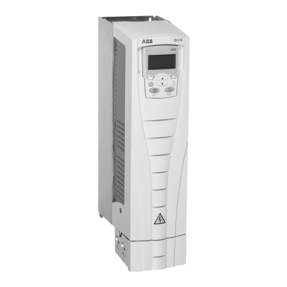
ABB ACH550-UH User Manual
Hide thumbs
Also See for ACH550-UH:
- User manual (642 pages) ,
- Installation, operation & maintenance manual (95 pages) ,
- User manual (307 pages)
Table of Contents
Advertisement
ACH550-UH User's Manual
Diagnostics
Warning! Do not attempt any measurement, parts replacement or other service
procedure not described in this manual. Such action will void the warranty, may
endanger correct operation, and increase downtime and expense.
Warning! All electrical installation and maintenance work described in this chapter
should only be undertaken by qualified service personnel. The Safety instructions on
the first pages of this manual must be followed.
Diagnostic displays
The drive detects error situations and reports them using:
• The green and red LED on the body of the drive
• The status LED on the control panel (if the HVAC control panel is attached to the
drive)
• The control panel display (if the HVAC control panel is attached to the drive)
• The Fault Word and Alarm Word parameter bits (parameters 0305 to 0309). See
Group 03: ACTUAL SIGNALS
The form of the display depends on the severity of the error. You can specify the
severity for many errors by directing the drive to:
• Ignore the error situation.
• Report the situation as an alarm.
• Report the situation as a fault.
Red – faults
The drive signals that it has detected a severe error, or fault, by:
• Enabling the red LED on the drive (LED is either steady on or blinking).
• Setting an appropriate bit in a Fault Word parameter (0305 to 0307).
• Overriding the control panel display with the display of a fault code.
• Stopping the motor (if it was on).
The fault code on the control panel display is temporary. Pressing any of the
following buttons removes the fault message: MENU, ENTER, UP button or DOWN
button. The message reappears after a few seconds if the control panel is not
touched and the fault is still active.
on page 1-87.
1-281
Diagnostics
Advertisement
Table of Contents

Summary of Contents for ABB ACH550-UH
- Page 1 ACH550-UH User’s Manual 1-281 Diagnostics Warning! Do not attempt any measurement, parts replacement or other service procedure not described in this manual. Such action will void the warranty, may endanger correct operation, and increase downtime and expense. Warning! All electrical installation and maintenance work described in this chapter should only be undertaken by qualified service personnel.
- Page 2 1-282 ACH550-UH User’s Manual Flashing green – alarms For less severe errors, called alarms, the diagnostic display is advisory. For these situations, the drive is simply reporting that it had detected something “unusual.” In these situations, the drive: • Flashes the green LED on the drive (does not apply to alarms that arise from control panel operation errors).
- Page 3 ACH550-UH User’s Manual 1-283 Fault Fault Name In Description and Recommended Corrective Action Code Panel Not used. ESERVED Intermediate circuit DC voltage is not sufficient. Check for and correct: DC UNDERVOLT • Missing phase in the input power supply. • Blown fuse.
- Page 4 Contact your local ABB sales representative. Internal fault. A communication-related problem has been detected on the OPEX LINK fiber optic link between the OITF and OINT boards. Contact your local ABB sales representative. Internal fault. Low voltage condition detected on OINT power supply.
- Page 5 CB OVERTEMP Check for and correct: • Excessive ambient temperatures • Fan failure. • Obstructions in the air flow. Error internal to the drive. Contact your local ABB sales representative and SERF CORRUPT report the error number. RESERVED SERF MACRO...
- Page 6 1-286 ACH550-UH User’s Manual Fault Fault Name In Description and Recommended Corrective Action Code Panel Error in the system. Contact your local ABB sales representative and report DSP T the error number. OVERLOAD DSP T OVERLOAD DSP T OVERLOAD DSP STACK...
- Page 7 ACH550-UH User’s Manual 1-287 Fault Fault Name In Description and Recommended Corrective Action Code Panel 1009 Parameter values for power control are inconsistent: Improper motor PAR PCU nominal frequency or speed. Check for both of the following: • 1 < (60 * 9907 / 9908 <...
- Page 8 1-288 ACH550-UH User’s Manual History For reference, the last three fault codes are stored into parameters 0401, 0412, 0413. For the most recent fault (identified by parameter 0401), the drive stores additional data (in parameters 0402…0411) to aid in troubleshooting a problem. For example, parameter 0404 stores the motor speed at the time of the fault.
- Page 9 ACH550-UH User’s Manual 1-289 Alarm Display Description Code 2006 Analog input 1 is lost, or value is less than the minimum setting. LOSS Check: • Input source and connections • Parameter that sets the minimum (3021) • Parameter that sets the Alarm/Fault operation (3001) 2007 Analog input 2 is lost, or value is less than the minimum setting.
- Page 10 1-290 ACH550-UH User’s Manual Alarm Display Description Code 2015 This alarm warns that the PFA interlocks are active, which means that PFA INTERLOCK the drive cannot start the following: • Any motor (when Autochange is used), • The speed regulated motor (when Autochange is not used).


