ABB ACH550-UH HVAC Installation, Operation & Maintenance Manual
Ach550 drives (1-550 hp); e-clipse bypass drives (1-400 hp); packaged dr
ives with disconnect (1-500 hp)
Hide thumbs
Also See for ACH550-UH HVAC:
- User manual (642 pages) ,
- User manual (454 pages) ,
- User manual (348 pages)
Table of Contents
Advertisement
Quick Links
ACH550
Installation, Operation and Maintenance Manual (I, O & M)
ACH550-UH HVAC Drives (1
550 HP)
...
ACH550-BCR/BDR/VCR/VDR E-Clipse Bypass Drives (1
400 HP)
...
ACH550-PCR/PDR Packaged Drives with Disconnect (1
550 HP)
...
Advertisement
Table of Contents

Related Manuals for ABB ACH550-UH HVAC


Summary of Contents for ABB ACH550-UH HVAC
- Page 1 ACH550 Installation, Operation and Maintenance Manual (I, O & M) ACH550-UH HVAC Drives (1 550 HP) … ACH550-BCR/BDR/VCR/VDR E-Clipse Bypass Drives (1 400 HP) … ACH550-PCR/PDR Packaged Drives with Disconnect (1 550 HP) …...
- Page 2 Note: For more technical information, contact • WARNING! Disconnect the internal EMC the factory or your local ABB representative. filter when installing the drive on an IT system (an ungrounded power system or a Safety...
- Page 3 V.2.06B 2030700001 • Type code label attached on the heat sink – on 2030700001 the side of the enclosure. ABB Inc. Input 3 PH 48…63 Hz 1 PH 4…63 Hz Voltage (U1) 200…240 Vac 200…240 Vac...
- Page 4 ACH550 Installation, Operation and Maintenance Manual 1. Prepare for installation Lifting R1…R6 Lift the drive only by the metal chassis. Lifting R7…R8 WARNING! Handle and ship floor mounted enclosures only in the upright position. These units are not designed to be laid on their backs. 1.
- Page 5 ACH550 Installation, Operation and Maintenance Manual • Mounting hardware: screws or nuts and bolts, four each. The type of hardware depends on the mounting surface and the frame size: Frame Size Mounting Hardware Note R1…R4 1/4 in 5/16 in R7…R8 7/16 Secures free standing cabinets if required.
- Page 6 ACH550 Installation, Operation and Maintenance Manual Note: Frame sizes R7 and R8 have mounting holes inside the enclosure base. Where it is not possible to use either mounting hole at the back of the base, use an L-bracket at the top of the enclosure to secure the cabinet to a wall or to the back of another enclosure.
- Page 7 2. Install and tighten mounting bolts. 5. Install wiring WARNING! Ensure the motor is compatible for use with the ACH550. The ACH550 must be installed by a competent person. If in doubt, contact your local ABB sales or service office. Conduit kit Wiring R1…R6 drives with the UL type 1 Enclosure requires a conduit kit with the...
- Page 8 ACH550 Installation, Operation and Maintenance Manual Connection diagrams The following diagrams show: • The terminal layout for frame size R3, which, in general, applies to frame sizes R6, except for the R5/R6 power and ground terminals. … • The R5/R6 power and ground terminals. •...
- Page 9 ACH550 Installation, Operation and Maintenance Manual X0011 Power Output to Motor Power Input (U2, V2, W2) (U1, V1, W1) Terminals Not Used Terminals Not Used X0013 Power Input Power Output to Motor (U1, V1, W1) (U2, V2, W2) WARNING! To avoid danger, or damage to the drive, on IT systems and corner grounded TN systems, see section Disconnecting the internal EMC filter page 10.
- Page 10 ACH550 Installation, Operation and Maintenance Manual R7 (R8 Similar) Ground Lug Motor Control Wires ACH550 Terminals (X1) Input Power Terminals Terminal Strip Only on ACH550-UH Disconnecting the internal EMC filter On certain types of systems, you must disconnect the internal EMC filter, otherwise the system will be connected to ground potential through the EMC filter capacitors, which might cause danger, or damage the drive.
- Page 11 ACH550 Installation, Operation and Maintenance Manual Ground connections For personnel safety, proper operation and to reduce electromagnetic emission/pick- up, the drive and the motor must be grounded at the installation site. • Conductors must be adequately sized as required by safety regulations. •...
- Page 12 ACH550 Installation, Operation and Maintenance Manual EM3 (an M4x16 screw) makes an internal ground connection that reduces electro-magnetic emission. Where EMC (electro- magnetic compatibility) is a concern, and the network is symmetrically grounded, EM3 may be installed. For reference, the diagram at right illustrates a symmetrically grounded network.
- Page 13 ACH550 Installation, Operation and Maintenance Manual R1…R6, wiring UL type 1 enclosure 1. Open the appropriate knockouts in the conduit box. (See Conduit kit on page 7.) 2. Install thin-wall conduit clamps (not supplied). X0007 3. Install conduit box. 4. Connect conduit runs for input power, motor and control cables to the box.
- Page 14 ACH550 Installation, Operation and Maintenance Manual R1…R6, wiring UL type 12 enclosure 1. Step depends on Frame Size: R1…R4 • Frame Sizes R1…R4: Remove and discard the cable seals where conduit will be installed. (The cable seals are cone-shaped, rubber seals on IP5013 the bottom of the drive.) •...
- Page 15 ACH550 Installation, Operation and Maintenance Manual R7…R8, wiring (both enclosure types) The figures show connections in the R7 cabinet, the R8 cabinet is similar. 1. Remove the conduit connection plate from the top of the left bay. 2. Route the input power, motor and control cables to the top of the cabinet.
- Page 16 ACH550 Installation, Operation and Maintenance Manual Drive’s power connection terminals The following table provides specifications for the drive’s power connection terminals. U1, V1, W1 U2, V2, W2 Earthing PE Terminal Frame BRK+, UDC+ Terminals Size Min. Wire Size Max. Wire Size Torque Max.
- Page 17 ACH550 Installation, Operation and Maintenance Manual Drive Control Terminal Description Terminal for signal cable screen. (Connected internally to chassis ground.) Analog input channel 1, programmable. Default = external reference. Resolution 0.1%, accuracy ±1%. J1:AI1 OFF: 0(2)…10 V (R = 312 k) or, for OFF for ON = 100 )
- Page 18 ACH550 Installation, Operation and Maintenance Manual You can wire the digital input terminals in either a PNP or NPN configuration. PNP connection (source) NPN connection (sink) 10 +24V 10 +24V 11 GND 11 GND 12 DCOM 12 DCOM 13 DI1 13 DI1 14 DI2 14 DI2...
- Page 19 ACH550 Installation, Operation and Maintenance Manual 8. Apply power Always re-install the covers before turning power on. WARNING! The ACH550 will start up automatically at power up, if the external run command is on. Apply input power. When power is applied to the ACH550, the green LED comes on. Note: Before increasing motor speed, check that the motor is running in the desired direction.
- Page 20 ACH550 Installation, Operation and Maintenance Manual operates the motor without any commissioning, except entry of the motor data as described below. Spin Motor is useful, for example, to operate ventilation fans prior to commissioning. Note: When using Spin Motor, the motor speed is limited to the range 1/3…2/3 of maximum speed.
- Page 21 ACH550 Installation, Operation and Maintenance Manual Operation The ACH550 HVAC control panel (ACS-CP-B) features: Status LED (Green when normal, if flashing or red, see Diagnostics.) SOFT SOFT KEY 2 KEY 1 DOWN AUTO HELP (always available) HAND X0201 General display features Soft key functions The soft key functions are defined by text displayed just above each key.
- Page 22 ACH550 Installation, Operation and Maintenance Manual Operating the drive AUTO/HAND – The very first time the drive is powered up, it is in the auto control (AUTO) mode, and is controlled from the Control terminal block X1. To switch to hand control (HAND) and control the drive using the control panel, press and hold the button.
- Page 23 ACH550 Installation, Operation and Maintenance Manual Start-up by changing the parameters individually To change the parameters, follow these steps: Select MENU to enter the main menu. Select the Parameters mode with the UP/ DOWN buttons and select ENTER to select the Parameters mode. Select the appropriate parameter group with the UP/DOWN buttons and select Select the appropriate parameter in a...
- Page 24 ACH550 Installation, Operation and Maintenance Manual Diagnostics Fault listing Fault Fault Name In Description and Recommended Corrective Action Code Panel Output current is excessive. Check for and correct: OVERCURRENT • Excessive motor load. • Insufficient acceleration time (parameters 2202 1 and ACCELER TIME 2205 ACCELER TIME...
- Page 25 Contact your local ABB sales representative. Internal fault. A communication-related problem has been detected on the OPEX LINK fiber optic link between the OITF and OINT boards. Contact your local ABB sales representative. Internal fault. Low voltage condition detected on OINT power supply.
- Page 26 Internal fault. Configuration Block Drive ID is not valid. Contact your local DRIVE ID ABB sales representative. Internal configuration file has an error. Contact your local ABB sales CONFIG FILE representative. Fieldbus communication has timed out. Check for and correct: SERIAL •...
- Page 27 Condition defined by parameter 3701 USER LOAD C MODE has been valid USER LOAD longer than the time defined by 3703 USER LOAD C TIME. CURVE Error internal to the drive. Contact your local ABB sales representative and SERF CORRUPT report the error number. RESERVED...
- Page 28 ACH550 Installation, Operation and Maintenance Manual Fault Fault Name In Description and Recommended Corrective Action Code Panel 1002 RESERVED (Obsolete) 1003 Parameter values are inconsistent. Check for any of the following: PAR AI SCALE • 1301 > 1302 • 1304 >...
- Page 29 ACH550 Installation, Operation and Maintenance Manual To clear the fault history (all of the Group 04, Fault History parameters): 1. Using the control panel in Parameters mode, select parameter 0401. 2. Press EDIT. 3. Press UP and Down simultaneously. 4. Press SAVE. Alarm listing The following table lists the alarms by code number and describes each.
- Page 30 ACH550 Installation, Operation and Maintenance Manual Alarm Display Description Code 2008 Panel communication is lost and either: PANEL LOSS • Drive is in local control mode (the control panel displays HAND or OFF), or • Drive is in remote control mode (AUTO) and is parameterized to accept start/stop, direction or reference from the control panel.
- Page 31 ACH550 Installation, Operation and Maintenance Manual Alarm Display Description Code 2019 Performing ID run. ID RUN 2020 This alarm warns that the Override function is active, which may start OVERRIDE the motor. 2021 This alarm warns that the Start Enable 1 signal is missing. START ENABLE MISSING •...
- Page 32 ACH550 Installation, Operation and Maintenance Manual Maintenance intervals If installed in an appropriate environment, the drive requires very little maintenance. This table lists the routine maintenance intervals recommended by ABB. Maintenance Application Interval Instruction Check/replace R7/R8 R7/R8 UL type 12 Check every 3 Frame Sizes R7/R8 –...
- Page 33 If the drive is operated in a critical part of a process, fan replacement is recommended once these symptoms start appearing. Replacement fans are available from ABB. Do not use other than ABB specified spare parts. To monitor the running time of the cooling fan, see Group 29: MAINTENANCE TRIG instructions.
- Page 34 ACH550 Installation, Operation and Maintenance Manual Enclosure fan replacement – UL Type 12 enclosures UL type 12 enclosures include an additional fan (or fans) to move air through the enclosure. Frame Sizes R1 to R4 To replace the internal enclosure fan in frame sizes R1 to R4: 1.
- Page 35 Then remove the four screws attaching the fan to the fan frame. Remove the old fan. PC00020 6. Install the new fan and capacitor with the replacement part for ABB Capacitor in the reverse order of the above. Ensure the fan is centered on the...
- Page 36 ACH550 Installation, Operation and Maintenance Manual 2. Lay the filter frame on a flat work surface. Remove the 3 retaining brackets by squeezing the tabbed corners in towards the middle of each bracket until the bracket clears the filter frame. Save these brackets for replacement.
- Page 37 ACH550 Installation, Operation and Maintenance Manual Frame Sizes R7/R8 – UL type 12 enclosure exhaust filters The exhaust filters in the R7/R8 UL type 12 enclosure are located in the exhaust box at the top of the enclosure. There are 2 filter frames attached to the exhaust box.
- Page 38 It is not possible to predict a capacitor failure. Capacitor failure is usually followed by a input power fuse failure or a fault trip. Contact ABB if capacitor failure is suspected. Replacements for frame size R5, R6 and R8 are available from ABB. Do not use other than ABB specified spare parts.
- Page 39 ACH550 Installation, Operation and Maintenance Manual ACH550 E-Clipse Bypass Installation – drive Follow the Installation instructions for the drive on page 3. Failure to observe the warnings and instructions may cause a malfunction or personal hazard. WARNING! Before you begin read Safety on page 2.
- Page 40 ACH550 Installation, Operation and Maintenance Manual Connection diagrams – Vertical E-Clipse Bypass ACH550 Vertical E-Clipse Bypass units are configured for wiring access from the bottom only. The following figure shows the Vertical E-Clipse Bypass wiring connection points. ACH550 E-Clipse Bypass Control Board Terminals (X2) Service Switch...
- Page 41 ACH550 Installation, Operation and Maintenance Manual Connection diagrams – Standard E-Clipse Bypass (wall mounted) ACH550 Standard E-Clipse Bypass units are configured for wiring access from the top. The following figure shows the Standard E-Clipse Bypass (wall mounted) wiring connection points. ACH550 User Power Cable Guides...
- Page 42 ACH550 Installation, Operation and Maintenance Manual User Power Cable Guides ACH550 Drive E-Clipse Bypass Control Board Terminals (X2) Disconnect Switch or Circuit Breaker Input Ground Lug Input Power Terminals Motor Terminals Output Ground Lug Service Switch (optional) ACH550 Drive Output Ground Lug Input Ground Lug Motor Terminals Input Power Terminals...
- Page 43 ACH550 Installation, Operation and Maintenance Manual Connection diagrams – Standard E-Clipse Bypass (R8, floor mounted) ACH550 Standard E-Clipse Bypass units are configured for wiring access from the top. The following figure shows the Standard E-Clipse Bypass (floor mounted) wiring connection points. ACH550 Drive Ground Lug Bar Motor Terminals...
- Page 44 ACH550 Installation, Operation and Maintenance Manual Power connections – Vertical E-Clipse Bypass configurations Line input connections Connect the input power to the terminals at the bottom of the disconnect switch or circuit breaker as shown below. Also see Connection diagrams – Vertical E-Clipse Bypass on page 40.
- Page 45 ACH550 Installation, Operation and Maintenance Manual User Power Cable Guides Ground Motor Motor Cables Cables Ground Input Power Cables Input Power Cables Standard Configuration (B3) Standard Configuration (B1/B2) Motor Cables Input Power Ground Cables Ground UL Type 3R Configuration (B1/B2) Note: UL Type 3R, B1/B2 enclosures are designed to be mounted on a wall.
- Page 46 ACH550 Installation, Operation and Maintenance Manual WARNING! Check the motor and motor wiring insulation before connecting the ACH550 to line power. Follow the procedure on page 12. Before proceeding with the insulation resistance measurements, check that the ACH550 is disconnected from incoming line power.
- Page 47 ACH550 Installation, Operation and Maintenance Manual Basic connections The figure on page shows the basic control connections for use with the E- Clipse Bypass HVAC Default macro. These connections are described in the following paragraphs. In typical installations, only analog input wires connect to the ACH550 terminal block, with other control connections made on the E-Clipse Bypass control...
- Page 48 ACH550 Installation, Operation and Maintenance Manual Vertical enclosure terminals Maximum Wire Size Capacities of Power Terminals Frame Identification Circuit Disconnect Motor Ground Size Breaker Switch Termination Lugs 208…240 Volt ACH550-VxR-04A6-2 ACH550-VxR-06A6-2 ACH550-VxR-07A5-2 35 in-lbs 7 in-lbs ACH550-VxR-012A-2 30 in-lbs 35 in-lbs ACH550-VxR-017A-2 ACH550-VxR-024A-2 40 in-lbs...
- Page 49 ACH550 Installation, Operation and Maintenance Manual Maximum Wire Size Capacities of Power Terminals Frame Identification Circuit Disconnect Motor Ground Size Breaker Switch Termination Lugs 500…600 Volt ACH550-VxR-02A7-6 ACH550-VxR-03A9-6 ACH550-VxR-06A1-6 62 in-lbs 30 in-lbs 35 in-lbs ACH550-VxR-09A0-6 7 in-lbs ACH550-VxR-011A-6 ACH550-VxR-017A-6 ACH550-VxR-022A-6 62 in-lbs 50 in-lbs...
- Page 50 ACH550 Installation, Operation and Maintenance Manual Standard enclosure terminals Power Wiring Data Base Circuit Circuit Disconnect Disconnect Motor Motor Ground Ground Drive Type Code Breaker Breaker Switch Switch Terminals Terminals Lugs Lugs Frame UL Type/ UL Type/ UL Type/ UL Type/ UL Type/ UL Type/ UL Type/...
- Page 51 ACH550 Installation, Operation and Maintenance Manual Power Wiring Data Base Circuit Circuit Disconnect Disconnect Motor Motor Ground Ground Drive Breaker Breaker Switch Switch Terminals Terminals Lugs Lugs Type Code Frame UL Type/ UL Type/ UL Type/ UL Type/ UL Type/ UL Type/ UL Type/ UL Type/...
- Page 52 ACH550 Installation, Operation and Maintenance Manual Power Wiring Data Base Circuit Circuit Disconnect Disconnect Motor Motor Ground Ground Drive Breaker Breaker Switch Switch Terminals Terminals Lugs Lugs Type Code Frame UL Type/ UL Type/ UL Type/ UL Type/ UL Type/ UL Type/ UL Type/ UL Type/...
- Page 53 ACH550 Installation, Operation and Maintenance Manual Basic control connections for E-Clipse HVAC Default Parameters Changed Relative to E-Clipse HVAC Default Parameter Number Description Setting Smoke Control (Override1) is a fixed input. Closing Digital Input 6 will place the E-Clipse Bypass in Smoke Control mode which may reassign the function of the other Digital Inputs.
- Page 54 ACH550 Installation, Operation and Maintenance Manual 2. Check installation – bypass Control panel settings and checks Apply power to the E-Clipse Bypass unit. The ACH550 Control Panel should show the operating status of the drive. If the E-Clipse Bypass Control Panel displays a PHASE SEQ (Phase Sequence) fault, remove power, wait at least 5 minutes and then swap any two input phase wires.
- Page 55 ACH550 Installation, Operation and Maintenance Manual • Parameter 1608 must be set to “Comm” • Parameter 5303 must be set to “76.8 kb/s” • Parameter 5304 must be set to “8 EVEN 1” • Parameter 5305 must be set to “DCU PROFILE” •...
- Page 56 ACH550 Installation, Operation and Maintenance Manual 3. Apply power to the E-Clipse Bypass unit. The ACH550 Control Panel display should be illuminated. On the bypass control panel, both the display and Enabled LED should be illuminated. If the Enabled LED is not illuminated solid green, check to see that closed contacts or jumpers connect terminal X2:3 to X2:4 and X2:2 to X2:7 on the bypass control board.
- Page 57 ACH550 Installation, Operation and Maintenance Manual Note: Both the ACH550 Drive and the E-Clipse Bypass include preset application macros. The only ACH550 Drive macro that provides the proper configuration settings by default is the E-Clipse HVAC Default macro (9902 = 15). If any other ACH550 drive macro or any modified setting of the E-Clipse HVAC Default macro is used the following ACH550 Drive parameter values must be set and power cycled or the E-Clipse Bypass will not function properly:...
- Page 58 ACH550 Installation, Operation and Maintenance Manual 5. On the E-Clipse Bypass control panel, either the Drive Selected or Bypass Selected LED should be illuminated. Pressing the Drive Select or Bypass Select key should switch the bypass back and forth between the Drive mode and the Bypass mode as indicated by the LEDs above each button.
- Page 59 ACH550 Installation, Operation and Maintenance Manual If the ACH550 Drive and E-Clipse Bypass operate according to these steps, and you have familiarized yourself with their operation, disconnect and lock out power to prepare for the next test. WARNING! Wait at least five minutes after disconnecting power from the drive before you attempt to service the drive.
- Page 60 On some ACH550 E-Clipse Bypasses, the circuit breaker has adjustable settings for instantaneous current protection. The factory default settings are practical for most applications. Refer to the “ABB SACE Instruction Sheet” (supplied with these units) for additional information on the adjustment of these settings.
- Page 61 ACH550 Installation, Operation and Maintenance Manual The following shows the front view of the ACH550 E-Clipse Bypass vertical configuration, and identifies the major components. ACH550 Drive ACH-CP-B Control Panel E-Clipse Bypass Control Panel Operating Handle for Disconnect Switch or Circuit Breaker E-Clipse Bypass BP0091 The following shows the front view of the ACH550 E-Clipse Bypass standard...
- Page 62 ACH550 Installation, Operation and Maintenance Manual The following is a typical power diagram. Drive with E-Clipse Bypass Disconnect Switch Drive Output Bypass or Circuit Breaker Contactor Control 3 Phase ACH550 Motor Drive Input Power Service Switch Bypass (Optional) Contactor Drive Input Fuse Bypass control The bypass control panel features: “Ready Indication”...
- Page 63 ACH550 Installation, Operation and Maintenance Manual Motor Run LED The Motor Run LED is illuminated green when the motor is running in either bypass mode or in drive mode. The Motor Run LED flashes green to indicate the system has been placed in an Override condition.
- Page 64 ACH550 Installation, Operation and Maintenance Manual Bypass Select Key The Bypass Select Key selects the bypass as the power source for the motor. Off/Reset Key The Off/Reset Key may be used to manually stop the motor if the motor has been running on bypass power.
- Page 65 ACH550 Installation, Operation and Maintenance Manual Select the Startup Params with the Up/Down arrows and press ENTER. ENTER Select the appropriate Parameter with * 1 6 0 1 S T A R T / S T O P the Up/Down arrows and press ENTER ENTER.
- Page 66 ACH550 Installation, Operation and Maintenance Manual Press ESC to return to the Default Display from the Main Menu. Note: In the Parameter Edit mode the current parameter value appears below the parameter name. Note: To view the default parameter value, press the Up/Down arrows simultaneously.
- Page 67 ACH550 Installation, Operation and Maintenance Manual Fault Fault Name In Fault Possible Cause Corrective Action Code Panel 3004 BYPASS COIL M2 contactor will not Loose J8 connector on Verify that J8 connector OPEN close when RBCU is firmly seated. commanded to do so Loose wires on With incoming power contactor terminals A1...
- Page 68 ACH550 Installation, Operation and Maintenance Manual Fault Fault Name In Fault Possible Cause Corrective Action Code Panel 3010 INP PHASE A Fault will be generated Loose J7 connector Check J7 connector LOSS only when trying to Loose wiring on Check yellow wire on close the bypass Contactor assembly.
- Page 69 Bad RBCU values 3027 INVALID SUB ASM Contactor assembly as RBCU unit from a Contact ABB at recorded in the RBCU different size bypass 1-800-HELP-365 unit does not match used to replace a Option 4 drive information defective RBCU.
- Page 70 ACH550 Installation, Operation and Maintenance Manual Fault Fault Name In Fault Possible Cause Corrective Action Code Panel 3028 EXT COMM LOSS Time between fieldbus Incorrect Check Group 51 & 53 messages has Communication Tighten Connections exceeded timeout settings in Group 51 & Check Communication interval set with Cable Grounding...
- Page 71 Fault Possible Cause Corrective Action Code Panel 3102 PMAP FILE Parameter file is Cycle Power corrupt Contact ABB with information that preceeded fault 3201 T1 OVERLOAD T1 program cycle is Contact ABB with overloaded information that proceeded fault Cycle Power...
- Page 72 ACH550 Installation, Operation and Maintenance Manual Alarm listing The following table lists the alarms by code number and describes each. Alarm Alarm Name In Alarm Possible Cause Corrective Action Code Panel 4001 INP PHASE A Alarm will occur in drive Loose J8 connector Check J8 connector LOSS...
- Page 73 ACH550 Installation, Operation and Maintenance Manual Alarm Alarm Name In Alarm Possible Cause Corrective Action Code Panel 4008 DRIVE SETUP Alarm generated when Incorrect parameters Set Parameter 1001 to configuration of drive is settings “COMM” such that bypass can Set Parameter 1002 to not properly control the “COMM”...
- Page 74 ACH550 Installation, Operation and Maintenance Manual Alarm Alarm Name In Alarm Possible Cause Corrective Action Code Panel 4016 INP VOLTAGE 3-Phase input voltage Loose J7 connector has not reached a Low input voltage. sufficient level to Incoming voltage has enable editing of not reached at least parameters via the 155 VAC within a few...
- Page 75 ACH550 Installation, Operation and Maintenance Manual Alarm Alarm Name In Alarm Possible Cause Corrective Action Code Panel 4024 Selected by PAR Alarm will occur when Run Enable condition is Check 24 Volts on 1624 start order is given and not satisfied. RBCU unit the “RUN Enable”...
- Page 76 ACH550 Installation, Operation and Maintenance Manual Bypass status listing Bypass Status Condition Description (16 Characters) DRIVE/BYPASS? DRIVE SELECTED Displays which one is selected, drive or BYPASS SELECTED bypass SAFETIES? OPEN Displays if safeties (=START ENABLE 1 and/ CLOSED or START ENABLE 2) have been applied, or if they are missing RUN PERMISSIVES? OPEN...
- Page 77 ACH550 Installation, Operation and Maintenance Manual Error messages Error Message Description CAN’T EDIT Try to save value (=press the ENTER key in Parameter Edit State) of a read- only parameter. E.g. try to change value PAR 01.02 INPUT VOLT PAR IS READ ONLY CAN’T EDIT Try to change value of a parameter, which is allowed to be changed only when system is not started.
- Page 78 ACH550 Installation, Operation and Maintenance Manual ACH550 E-Clipse Bypass...
- Page 79 ACH550 Installation, Operation and Maintenance Manual ACH550-PCR/PDR Installation This information is unique to ACH550 input disconnect configurations (PCR or PDR). The ACH550 with Input Disconnect is an ACH550 AC adjustable frequency drive packaged with an input disconnect switch or circuit breaker. Refer to the Installation instructions on page 3, for all other information.
- Page 80 ACH550 Installation, Operation and Maintenance Manual Connection diagrams – standard drive with input disconnect (wall mounted) The following figure shows the Standard Drive with Input Disconnect (wall mounted) wiring connection points. UL Type / NEMA 1 & 12 UL Type / NEMA 1 & 12 ACH550 Vertical Construction Hinged Door Wall Mount...
- Page 81 ACH550 Installation, Operation and Maintenance Manual Connection diagrams – standard drive with input disconnect (floor mounted) Floor mounted UL Type / NEMA 1 & 12 Drive with Input Disconnect units are configured for wiring access from the top and include a removable conduit mounting plate.
- Page 82 ACH550 Installation, Operation and Maintenance Manual Line input connections – standard drive with input disconnect configurations Connect input power to the terminals of the disconnect switch or circuit breaker. Connect the equipment grounding conductor to the ground lug at the top of the enclosure.
- Page 83 ACH550 Installation, Operation and Maintenance Manual Power connection terminals The following tables show maximum wire size and required tightening torque for incoming power, grounding and motor terminals. 208/240 Volt Power Wiring Data Base Circuit Circuit Disconnect Disconnect Ground Ground Drive Breaker Breaker Switch...
- Page 84 ACH550 Installation, Operation and Maintenance Manual 480 Volt Power Wiring Data Base Circuit Circuit Disconnect Disconnect Ground Ground Drive Breaker Breaker Switch Switch Lugs Lugs Motor Frame Type Code UL Type / UL Type/ UL Type/ UL Type/ UL Type/ UL Type/ Terminals Size...
- Page 85 ACH550 Installation, Operation and Maintenance Manual 600 Volt Power Wiring Data Circuit Disconnect Circuit Disconnect Ground Ground Frame Breaker Switch Breaker Switch Lugs Lugs Motor Size Type Code UL Type UL Type UL Type UL Type UL Type UL Type Terminals / NEMA / NEMA...
- Page 86 ACH550 Installation, Operation and Maintenance Manual UL Type / NEMA 3R Enclosures Input Power WARNING! Check the motor and motor wiring insulation before connecting the ACH550 to line power. Follow the procedure on page 12. Before proceeding with the insulation resistance measurements, check that the ACH550 is disconnected from incoming line power.
- Page 87 ACH550 Installation, Operation and Maintenance Manual Operation This information is unique to ACH550 input disconnect configurations (PCR or PDR). Refer to the Operation instructions on page for all other information. Input disconnect configuration The ACH550 with Input Disconnect is an ACH550 AC adjustable frequency drive packaged with an input disconnect switch or circuit breaker, and with a door interlocked, external operating handle.
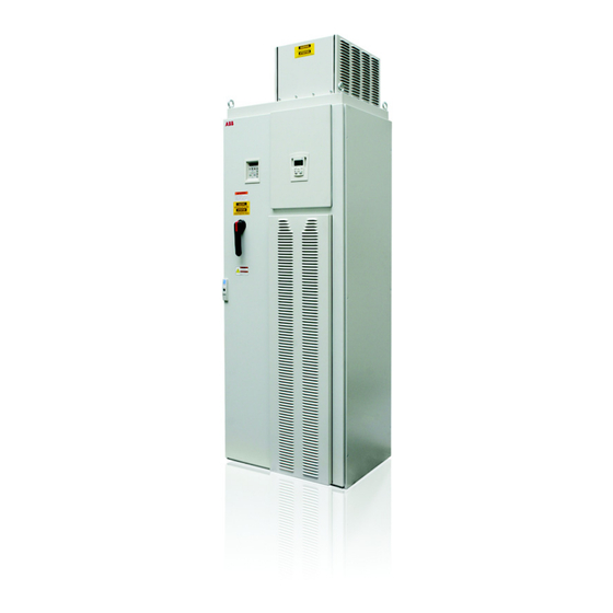
- Page 88 ACH550 Installation, Operation and Maintenance Manual The following shows the front view of the ACH550 Drive with Input Disconnect standard configurations, and identifies the major components. UL Type / NEMA 1 & 12 UL Type / NEMA 1 & 12 UL Type / NEMA 1 &...
- Page 89 ACH550 Installation, Operation and Maintenance Manual Maintenance Maintenance intervals If installed in an appropriate environment, the drive requires very little maintenance. This table lists the routine maintenance intervals recommended by ABB for ACH550 enclosures in addition to the intervals on page 31. Maintenance Configuration...
- Page 90 ACH550 Installation, Operation and Maintenance Manual 3. Lift the filter out of the filter bracket and replace as appropriate. 4. With the filter in the filter bracket, align the hooks on the bracket with the slots in the enclosure base, and press the hooks up into the slots. 5.
- Page 91 ACH550 Installation, Operation and Maintenance Manual Complete ACH550 Drive Parameter List GROUP 01 GROUP 11 1706 OVERRIDE DIR 3004 EXTERNAL FAULT 2 3605 STOP DAY 1 OPERATING DATA REFERENCE SELECT 1707 OVERRIDE REF 3005 MOT THERM PROT 3606 START TIME 2 SPEED &...
- Page 92 ACH550 Installation, Operation and Maintenance Manual 4117 ACT2 INPUT 6410 UDC AT PEAK 0111 A-B VOLT 1620 RUN EN TXT 5120 FBA PAR 20 4118 ACT1 MINIMUM 6411 FREQ AT PEAK 0112 B-C VOLT 1621 ST EN1 TXT 5121 FBA PAR 21 4119 ACT1 MAXIMUM 6412...
- Page 93 ACH550 Installation, Operation and Maintenance Manual ACH550-PCR/PDR...
- Page 94 ACH550 Installation, Operation and Maintenance Manual ABB Inc. 16250 West Glendale Drive New Berlin, WI 53151 Telephone +1 800 752-0696 +1 262 785-0397 Internet www.abb.us/drives...