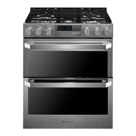
LG LUTD4919SN Installation Manual
Double oven range
Hide thumbs
Also See for LUTD4919SN:
- Owner's manual (132 pages) ,
- Quick start manual (2 pages) ,
- Owner's manual (67 pages)
Table of Contents
Advertisement
InSTALLATIOn
Installation Overview
Please read the following installation instructions first after purchasing this product or transporting it to another
location.
Check and choose the
proper location
Pressure regulator
Connect the range to gas
Product Specifications
The appearance and specifications listed in this manual may vary due to constant product improvements.
Oven range Models
Description
Electrical requirements
Exterior Dimensions
Height to cooking surface
net weight
Total capacity
Install anti-tip device
240 V or 208 V
Plug in the power cord
LUTD4919Sn
Dual Fuel Double Oven Range
6.9 kW 120/240 VAC or 5.2kW 120/208 VAC
29
/
" (W) x 37
/
" (H) x 28
7
59
8
64
75.9 cm (W) x 96.3 cm (H) x 73.5 cm (D) (D with door closed)
36" (91.4 cm)
196.2 lb (89.0 kg)
Upper Oven: 3.0 cu. ft.
Lower Oven: 4.3 cu. ft.
Total cap.: 7.3 cu. ft.
INSTALLATION
Black White Red
Conduit
connection
plate
Level the range
Connect electric range
Engage the anti-tip device
/
" (D) (D with door closed)
15
16
13
Terminal
block
Test run
Advertisement
Table of Contents

Summary of Contents for LG LUTD4919SN
-
Page 1: Product Specifications
Engage the anti-tip device Test run Product Specifications The appearance and specifications listed in this manual may vary due to constant product improvements. Oven range Models LUTD4919Sn Description Dual Fuel Double Oven Range Electrical requirements 6.9 kW 120/240 VAC or 5.2kW 120/208 VAC "... -
Page 2: Before Installing The Range
14 INSTALLATION Before Installing the range If you did not receive an anti-tip bracket with your purchase, call 1-800-984-6306 to receive one at no charge. WArnInG WArnInG Tip - Over Hazard • The information in this manual should be A child or adult can tip the range and followed exactly. -
Page 3: Preparing For Installation
INSTALLATION Preparing for Installation Tools needed Phillips screwdriver Flat-blade screwdriver " Nut driver Pliers Tape measure Level Open-end or Drill Safety glasses Gloves adjustable wrench Pipe wrench (2) (one for support) Parts Provided Parts not Provided Template (1) Anti-tip bracket kit (1) 4-Wire cord or Strain relief 3-Wire cord... -
Page 4: Installing The Range
16 INSTALLATION Installing the range Choosing the Proper Location CAUTIOn Unpacking and Moving the range • Avoid placing cabinets above the range. To CAUTIOn minimize the hazard caused by reaching over the open flames of operating burners, install a • You should use two or more people to move ventilation hood over the range that projects and install the range. - Page 5 INSTALLATION Mobile Home - Additional Installation requirements The installation of this range must conform to the Manufactured Home Construction and Safety Standard, Title 24 CFR, Part 3280 (formerly the Federal Standard for Mobile Home Construction and Safety, Title 24, HUD Part 280), or when such standard is not applicable, the Standard for Manufactured Home Installations, ANSI A225.1/NFPA 501A or with local codes.
-
Page 6: Dimensions And Clearances
18 INSTALLATION Dimensions and Clearances nOTE Save for the use of the local electrical inspector. 24" 3" (7.6 cm) (60.9 cm) 3" (7.6 cm) 25" Normal counter (63.5 cm) top depth Acceptable gas pipe and electrical Counter 36" outlet area top height (91.4 cm) Cabinet... -
Page 7: Installing The Anti-Tip Device
INSTALLATION Installing the Anti-tip Device Use a level to check your adjustments. Place the level diagonally on the oven rack, and check each direction WArnInG for level. First check direction . Tip - Over Hazard Then check direction . If the level doesn’t show level A child or adult can tip the range and on the rack, adjust the leveling legs with a wrench. -
Page 8: Providing Adequate Gas Supply
20 INSTALLATION Providing Adequate Gas Connecting the range to Gas Supply Shut off the range gas supply valve before removing the old range and leave it off until the new hook-up The range is designed to operate at a pressure of has been completed. -
Page 9: Connecting Electricity
INSTALLATION Flexible Connector Hookup WArnInG • Allow 2 to 3 ft (61.0 cm to 91.4 cm) of slack in the line so that the range can be moved if servicing is ever necessary. • The power supply cord and plug should "... - Page 10 22 INSTALLATION 3-Wire Connection : Power Cord Use the cord/conduit connection plate to install the power cord or conduit. Leave the connection plate WArnInG as installed for power cord installations. Remove the connection plate for conduit installations and use the •...
-
Page 11: Wire Connection: Conduit
INSTALLATION 4-Wire Connection : Power Cord 3-Wire Connection: Conduit Install the conduit as follows: WArnInG Remove the conduit connection plate from the rear of • Only a 4-conductor power-supply cord kit the oven and rotate it. The conduit hole (1 ") must rated 120/208 or 120/240 volts, 50 amperes be used. -
Page 12: Engaging The Anti-Tip Device
24 INSTALLATION Engaging the Anti-tip Device 4-Wire Connection: Conduit WArnInG • Move the range close enough to the opening to plug into the receptacle. • The white middle (neutral) wire of the power cord or 4-wire conduit has to be connected •... -
Page 13: Assembling The Surface Burners
INSTALLATION Assembling the Surface Quality of Flames Burners The combustion quality of the burner flames needs to be confirmed visually. A Yellow flames - Call for service. CAUTIOn Do not operate the burners without all parts in B Yellow tips on outer cones - This place.


