Table of Contents

Related Manuals for Fujitsu UTY-RVNUM


Summary of Contents for Fujitsu UTY-RVNUM
-
Page 1: Installation Manual
REMOTE CONTROLLER (WIRED TYPE) INSTALLATION MANUAL For authorized service personnel only. MANUEL D'INSTALLATION UTY-RVNUM Pour le personnel agréé uniquement. MANUAL DE INSTALACIÓN Sólo para personal de mantenimiento autorizado. PART No. 9380222057... -
Page 2: Table Of Contents
INSTALLATION MANUAL WARNING PART No. 9380222057 Do not install the unit in the following areas: • Do not install the unit near a source of heat, steam, or flammable gas. REMOTE CONTROLLER (WIRED TYPE) • Area filled with mineral oil or containing a large amount of splashed oil Contents or steam, such as a kitchen. -
Page 3: Accessories
2. ACCESSORIES 4. SELECTING AN INSTALLATION LOCATION The following installation parts are supplied. Use them as required. 4.1. Dimensions Name and Shape Q’ty Application 7/32 (21.3) 4-23/32 (120) Installation manual This manual Operating manual Instruction book for operation Remote controller cable For connecting the remote controller 1-6/32 1-10/32... -
Page 4: Installing The Remote Controller
5.2.1 When connecting to the wall mounted type 5. INSTALLING THE REMOTE CONTROLLER and the floor type connector Connect the remote controller cable to the connecting cable and insert it to 5.1. Wiring the connector. Pattern 1 Connecting cable Indoor unit Outdoor WARNING Connector... -
Page 5: Installation
5.3.4 Installing the remote controller 5.3. Installation A. When attaching to switch box: Seal the wiring hole of the remote controller cable. WARNING Put a remote controller cable through the hole of the rear case. When installing this unit, make sure that there are no children nearby. Fix the rear case by securing it with attached screws (2 places). -
Page 6: Setting The Dip Switch
5.3.5 Connect the cable to the terminals Switch state Detail Tightening torque Memory backup setting Terminal screw 7.1 to 10.6 lbf•in (0.8 to 1.2N • m) * Set to ON to use batteries for the memory backup. Invalidity Validity If batteries are not used, the settings information stored in memory will be deleted if there switch... -
Page 7: Installation Methods
6. INSTALLATION METHODS 7. TURNING ON THE POWER CAUTION 6.1. Group control Recheck the wiring. Incorrect wiring will cause trouble. • A number of indoor units can be operated at the same time using a single Check the remote controller wiring and DIP switch settings. remote controller. -
Page 8: Service Screen Setting
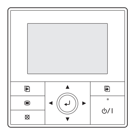
Set the “Day”, “Month”, and “Year”. 9.1. Test run Switch the setting item with [Cursor button (Left/Right)], and adjust with [Cursor button (Up/Down)]. • If the unit is operating, turn it off. When [Cancel button] is pressed, it returns to the “Change display •... -
Page 9: Error History
Select [Function setting] with pressing the [Cursor button (Up/Down)], 9.5. Version and press the [Enter button]. Service Software version of the remote controller can be displayed. Mo 10:00AM Select [Version] with the [Cursor button (Up/Down)], and press the [Enter Test run button]. -
Page 10: Management Function
1 ) Indoor room temperature sensor switching function Select [Password setting (Management)] in the “Initial” screen, and (Only for Wired remote controller) press the [Enter button]. The following settings are needed when use the control by Wired remote Initial Mo 10:00AM controller temperature sensor. -
Page 11: Others
When correct password is entered, “Management function” screen is -Note- displayed. If the function you are selecting is restricted by [Management] To select the function to be controlled by [Management], select [Edit] function, following message is displayed in the operation guidance with pressing the [Cursor button (Up/Down)], and press the [Enter display.