
Related Manuals for D-Link DGS-1100-05


Summary of Contents for D-Link DGS-1100-05
- Page 1 D G S - 1 1 0 0 - 0 5 / 0 8 / 0 8 P / 0 5 P D Ma n u a l S MA R T MA N A G E D S WI T C H V e r .
-
Page 2: Table Of Contents
Table of Contents D-Link Smart Managed Switch User Manual Table of Contents Table of Contents ............................. i About This Guide ............................. 1 Terms/Usage ..............................1 Copyright and Trademarks ..........................1 Product Introduction ........................... 2 DGS-1100-05 ..............................2 Front Panel ..............................2 Rear Panel .............................. - Page 3 Management > SNMP > SNMP Community Table Settings ..............21 Management > SNMP > SNMP Host Settings ..................22 Management > D-Link Discovery Protocol ....................22 L2 Features > FDB > Static FDB > Unicast Static FDB ................22 L2 Features > FDB > Static FDB > Multicast Static FDB ................. 23 L2 Features >...
-
Page 4: About This Guide
Reproduction in any manner whatsoever without the written permission of D-Link Corporation is strictly forbidden. Trademarks used in this text: D-Link and the D-LINK logo are trademarks of D-Link Corporation; Microsoft and Windows are registered trademarks of Microsoft Corporation. Other trademarks and trade names may be used in this document to refer to either the entities claiming the marks and names or their products. -
Page 5: Product Introduction
Versatile Management. The DGS-1100-05/05PD/08/08PD feature an intuitive, web-based management interface that allows administrators to remotely control their network down to the port level. The D-Link Network Assistant (DNA) easily allows administrators to discover multiple D-Link Smart Managed Switches within the same L2 network segment and display them on-screen for instant access. -
Page 6: Rear Panel
D-Link Smart Managed Switch User Manual Rear Panel Figure 1.2 – DGS-1100-05 Rear Panel Power: Input for a 5V/1A AC adapter. Reset: Press the Reset button for 1 to 5 seconds to reboot the Switch. Press the Reset button for 6 to10 seconds to reset the Switch back to the default settings. -
Page 7: Rear Panel
1 Product Introduction D-Link Smart Managed Switch User Manual Rear Panel Figure 1.4 – DGS-1100-05PD Rear Panel Power: Use RJ45 to connect the PD port (port 5) and Power over Ethernet Adapter Kit. Kensington Lock: This is used to attach a physical Kensington security lock. -
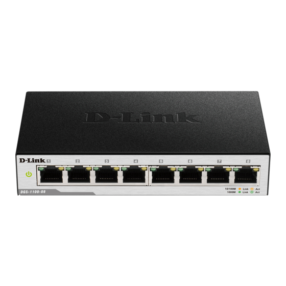
Page 8: Front Panel
1 Product Introduction D-Link Smart Managed Switch User Manual Front Panel Figure 1.7 – DGS-1100-08P Front Panel Power LED: The Power LED lights up when the Switch is connected to a power source. Reset: Press the Reset button for 1 to 5 seconds to reboot the Switch. Press the Reset button for 6 to10 seconds to reset the Switch back to the default settings. -
Page 9: Led Indicators
NOTE: The power budget is 64 Watts for DGS-1100-08P. LED Indicators The Switches feature LED indicators for Power and Link/Act for each port. The following shows the LED indicators for the DGS-1100-05/05PD/08/08PD switches along with an explanation of each indicator. Figure 1.9 –LED Indicators on DGS-1100 series Location... - Page 10 1 Product Introduction D-Link Smart Managed Switch User Manual Light off No link.
-
Page 11: Hardware Installation
2 Hardware Installation D-Link Smart Managed Switch User Manual Hardware Installation This chapter provides unpacking and installation information for your D-Link DGS-1100-05/05PD/08/08P Smart Managed Switch. Step 1: Unpacking Open the shipping carton and carefully unpack its contents. Please consult the packing list below to make sure all items are present and undamaged. - Page 12 2 Hardware Installation D-Link Smart Managed Switch User Manual Step 2. Hook the mounting keyholes on the back of the Switch onto the screws to secure the device to the wall. Figure 2.2 – Wall mount installation...
-
Page 13: Getting Started
This chapter introduces the management interface of D-Link Smart Managed Switch. Management Options The D-Link Smart Managed Switch can be managed through any port on the device by using the web-based management interface, or the D-Link Network Assistant (DNA). Each switch must be assigned its own IP address, which is used for communication with the web-based management interface or a SNMP network manager. -
Page 14: Web-Based Management
D-Link Network Assistant (DNA) D-Link Network Assistant (DNA) is a program that is used to discover switches which are in the same Layer 2 network segment as your PC. You can download the DNA App from the Chrome web store and install it in a Chrome web browser. -
Page 15: Configuration
Logout button first, then it will be seen as an abnormal exit and the login session will still be occupied. By clicking on the D-Link logo in the upper-left corner of the screen you will be redirected to the local D-Link website. -
Page 16: Tool Bar > Save Menu
4 Configuration D-Link Smart Managed Switch User Manual Tool Bar > Save Menu The Save Menu provides Save Configuration and Save Log functions. Figure 4.2 – Save Menu Save Configuration By clicking Apply, the current device configuration will be saved on the device’s flash memory. -
Page 17: Configuration Backup And Restore
Tool Bar > Online Help The Online Help provides two ways of online support: D-Link Support Site will lead you to the D-Link website where you can find online resources such as updated firmware images; User Guide can offer an immediate reference for the feature definition or configuration guide. -
Page 18: Device Information
4 Configuration D-Link Smart Managed Switch User Manual Figure 4.11 –Function Tree Device Information The Device Information provides an overview of the Switch, including essential information such as firmware and hardware information, and IP address. Figure 4.12 – Device Information System >... -
Page 19: System > System Information Settings > Ipv4 Interface
4 Configuration D-Link Smart Managed Switch User Manual System Contact Specify the system contact of the Switch. The Web Session Timeout controls the idle time-out period for security purposes, when there is no activity in the web Web Session Timeout interface within the specified time-out period. -
Page 20: System > Port Configuration > Jumbo Frame
System > Port Configuration > Jumbo Frame D-Link Smart Managed Switches support jumbo frames (frames larger than the Ethernet frame size of 1536 bytes) of up to 9216 bytes (tagged). This function is disabled by default. Select Enabled then click Apply to turn on the jumbo frame support. -
Page 21: System > Poe > Poe Configuration (Dgs-1100-05Pd/08P Only)
DGS-1100-08P Port 1 ~ Port 8: Max. PoE Output 30 Watts 64 Watts The DGS-1100-05PD/08P work with D-Link 802.3af or 802.3at capable devices. IEEE 802.3at defined that the PSE provides power according to the following classification: Class Usage Output power limit by PSE... - Page 22 4 Configuration D-Link Smart Managed Switch User Manual Default 15.4W Optional 4.0W Optional 7.0W Optional 15.4W Optional The PoE port table will display the PoE status including, Port Enable, Power Limit, Power (W), Voltage (V), Current (mA), Classification, Port Status. You can select From Port / To Port to control the PoE functions of a port.
-
Page 23: Management > Password Access Control
4 Configuration D-Link Smart Managed Switch User Manual Click Refresh button to update the port PoE status information. Note: For the PoE Port Settings table, if the classification was shown as “Legacy PD”, it will be classified to non-AF PD or Legacy PD. -
Page 24: Management > Snmp > Snmp Community Table Settings
4 Configuration D-Link Smart Managed Switch User Manual Item Description SNMP Global Settings Specify to enable or disable the SNMP feature. The default SNMP Global State setting is Disabled. Trap Settings Enable or disable SNMP trap notifications from client devices. -
Page 25: Management > Snmp > Snmp Host Settings
Click Apply to make the configurations take effect. Management > D-Link Discovery Protocol For devices that support the D-Link Discovery Protocol (DDP), this page allows users to enable or disable DDP, and configure the DDP packet report timer. Figure 4.23 – Management > D-Link Discovery Protocol... -
Page 26: L2 Features > Fdb > Static Fdb > Multicast Static Fdb
4 Configuration D-Link Smart Managed Switch User Manual Figure 4.24 – L2 Features > FDB > Static FDB > Unicast Static FDB The fields that can be configured for Unicast Static FDB are described below: Item Description Allows the selection of the port number on which the MAC address Port entered resides. -
Page 27: L2 Features > Fdb > Mac Address Table
4 Configuration D-Link Smart Managed Switch User Manual Figure 4.26 – L2 Features > FDB > MAC Address Table Settings The fields that can be configured for MAC Address Learning are described below: Item Description From Port / To Port Enter the appropriate port range used for the configuration. -
Page 28: L2 Features > Vlan > Port-Based Vlan
4 Configuration D-Link Smart Managed Switch User Manual The IEEE 802.1Q VLAN Configuration page provides powerful VID management functions. The original settings have the VID as 1, no default name, and all ports as “Untagged” Figure 4.28 – L2 Features > VLAN > 802.1Q VLAN Click Rename to rename the VLAN group. -
Page 29: L2 Features > Vlan > Management Vlan
4 Configuration D-Link Smart Managed Switch User Manual Figure 4.31 – L2 Features > VLAN > Port-Based VLAN Select Enabled and click Apply to enable the Port-Based VLAN function and the following will be displayed: Figure 4.32 – L2 Features > VLAN > Port-Based VLAN - Enabled Click Rename to rename the VLAN group. -
Page 30: L2 Features > Vlan > Asymmetric Vlan
L2 Features > VLAN > Surveillance VLAN Surveillance VLAN is a feature that allows you to place the video traffic from D-Link IP cameras to an assigned VLAN to enhance the IP surveillance service. With a higher priority and individual VLAN, the quality and the security of surveillance traffic are guaranteed. - Page 31 Specify the priority level. The levels of priority are High, Priority Medium and Low. The default priority is High. User-defined MAC Settings Surveillance VLAN will automatically detect D-Link surveillance devices by default. There are another five surveillance components that can be configured for surveillance VLAN. Component Type...
-
Page 32: L2 Features > Vlan > Voice Vlan
L2 Features > VLAN > Voice VLAN Voice VLAN is a feature that allows you to place the voice traffic from D-Link IP phones to an assigned VLAN to enhance the IP voice service. With a higher priority and individual VLAN, the quality and the security of voice traffic are guaranteed. -
Page 33: L2 Features > Spanning Tree > Stp Global Settings
4 Configuration D-Link Smart Managed Switch User Manual 00:60:B9 NEC / Philips nec&Philips 00:0F:E2 Huawei-3COM Huawei&3com 00:09:6E Avaya avaya Table 4.20 Click Apply to make the configurations take effect. Click Add to create a new Voice VLAN. L2 Features > Spanning Tree > STP Global Settings The Switch implements two versions of the Spanning Tree Protocol: Rapid Spanning Tree Protocol (RSTP) as defined by IEEE 802.1w, a version compatible with the IEEE 802.1D STP. -
Page 34: L2 Features > Spanning Tree > Stp Port Settings
4 Configuration D-Link Smart Managed Switch User Manual Root Port Display the root port. Table 4.21 Click Apply to make the configurations take effect. L2 Features > Spanning Tree > STP Port Settings STP can be set up per port. In addition to setting Spanning Tree parameters for use on the switch level, the Switch allows configuration of a spanning tree setup for a group of ports. -
Page 35: L2 Features > Loopback Detection
4 Configuration D-Link Smart Managed Switch User Manual L2 Features > Loopback Detection The Loopback Detection function is used to detect loops created by a specific port while Spanning Tree Protocol (STP) is not enabled in the network, especially when the down links are hubs or unmanaged switches. -
Page 36: L2 Features > L2 Multicast Control > Igmp Snooping > Igmp Snooping Settings
Click Apply to make the configurations take effect. Click Delete to remove the Link Aggregation group. NOTE: Maximum number of ports in a Link Aggregation group is 4. DGS-1100-05 only supports 1 Link Aggregation group, and DGS- 1100-08 supports up to 2 Link Aggregation groups. -
Page 37: L2 Features > L2 Multicast Control > Igmp Snooping > Igmp Snooping Group Settings
4 Configuration D-Link Smart Managed Switch User Manual Item Description Specify to enable or disable the IGMP Snooping function of the IGMP Snooping Switch. Table 4.25 Click Apply to make the configuration take effect. L2 Features > L2 Multicast Control > IGMP Snooping > IGMP Snooping Group Settings The IGMP Snooping Group Settings page allows user to configure static IGMP Snooping groups on the Switch. -
Page 38: Qos > Port Rate Limiting
The fields that can be configured are described below: Item Description Global Settings D-Link Smart Managed Switch allows the user to prioritize the traffic based on the 802.1p priority in the VLAN tag or the Select QoS mode DSCP (Differentiated Services Code Point) priority in the IP header. -
Page 39: Security > Traffic Segmentation
4 Configuration D-Link Smart Managed Switch User Manual The fields that can be configured for Port Rate Limiting are described below: Item Description From Port / To Port Specify a range of ports to be configured. Select the direction option. Options to choose from are: ... -
Page 40: Security > Port Security
4 Configuration D-Link Smart Managed Switch User Manual Item Description Storm Control Status Specify to enable or disable the storm control function. Specify the type of controlled packets, Options are Broadcast Storm Control Only, Multicast & Broadcast, and Multicast & Broadcast &... -
Page 41: Monitoring > Statistics > Port Counters
4 Configuration D-Link Smart Managed Switch User Manual Figure 4.49 - OAM > Cable Diagnostics Select a port and then click the Test Now button to start the diagnosis. The results will be displayed below: Figure 4.50 - OAM > Cable Diagnostics - results... -
Page 42: Monitoring > Mirroring Settings
4 Configuration D-Link Smart Managed Switch User Manual Monitoring > Mirroring Settings Port Mirroring is a method of monitoring network traffic that forwards a copy of each incoming and/or outgoing packet from one port of the Switch to another port, where the packet can be studied. This enables network managers to better monitor network performances. -
Page 43: Ethernet Technology
Ethernet Technology D-Link Smart Managed Switch User Manual Ethernet Technology This chapter will describe the features of the D-Link Smart Managed Switch and provide some background information about Ethernet/Fast Ethernet/Gigabit Ethernet switching technology. Gigabit Ethernet Technology Gigabit Ethernet is an extension of IEEE 802.3 Ethernet utilizing the same packet structure, format, and support for CSMA/CD protocol, full duplex, and management objects, but with a tenfold increase in theoretical throughput of over 100-Mbps Fast Ethernet and a hundredfold increase over 10-Mbps Ethernet. -
Page 44: Appendix A - Technical Specifications
Appendix A - Technical Specifications D-Link Smart Managed Switch User Manual Appendix A - Technical Specifications Key Components / Performance DGS-1100-05/05PD: 10 Gbps Switching Capacity DGS-1100-08/08P: 16 Gbps DGS-1100-05/05PD: 7.4 Mpps Max. Forwarding Rate DGS-1100-08/08P: 11.9 Mpps Forwarding Mode Store and Forward... - Page 45 Appendix A - Technical Specifications D-Link Smart Managed Switch User Manual Operation Temperature 0 ~ 40 °C Storage Temperature - 40 ~ 70 °C Operation Humidity 0%~90% RH Storage Humidity 0%~95% RH EMI Certifications CE, FCC, ITE, RCM, VCCI, BSMI, CCC...
-
Page 46: Appendix B - Regulatory Statements
Appendix B - Regulatory Statements D-Link Smart Managed Switch User Manual Appendix B - Regulatory Statements Federal Communication Commission Interference Statement This equipment has been tested and found to comply with the limits for a Class B digital device, pursuant to Part 15 of the FCC Rules. - Page 47 Appendix B - Regulatory Statements D-Link Smart Managed Switch User Manual SICHERHEITSVORSCHRIFTEN Die folgenden allgemeinen Sicherheitsvorschriften dienen als Hilfe zur Gewährleistung Ihrer eigenen Sicherheit und zum Schutz Ihres Produkts. Weitere Details finden Sie in den Benutzeranleitungen zum Produkt. • Statische Elektrizität kann elektronischen Komponenten schaden. Um Schäden durch statische Aufladung zu vermeiden, leiten Sie elektrostatische Ladungen von Ihrem Körper ab,...
- Page 48 Appendix B - Regulatory Statements D-Link Smart Managed Switch User Manual ISTRUZIONI PER LA SICUREZZA Las siguientes directrices de seguridad general se facilitan para ayudarle a garantizar su propia seguridad personal y para proteger el producto frente a posibles daños. No olvide consultar las instrucciones del usuario del producto para obtener más información.
- Page 49 D-Link recommends that you always switch off or unplug your D-Link products when they are not in use. By doing so you will help to save energy and reduce CO2 emissions.
- Page 50 D-Link e l'ambiente D-Link cerca da sempre di ridurre l'impatto ambientale dei propri stabilimenti e dei propri prodotti. Allo scopo di ridurre al minimo tale impatto, D-Link progetta e realizza i propri prodotti in modo che rispettino il più...
- Page 51 D-Link raadt aan om steeds uw D-Link producten uit te schakelen of uit de stekker te halen wanneer u ze niet gebruikt. Door dit te doen bespaart u energie en beperkt u de CO2-emissies.
- Page 52 životní prostředí i lidské zdraví. D-Link a životní prostředí Ve společnosti D-Link jsme si vědomi vlivu našich provozů a výrobků na životní prostředí a snažíme se o minimalizaci těchto vlivů. Proto své výrobky navrhujeme a vyrábíme tak, aby byly co nejekologičtější, a ve výrobcích i obalech používáme recyklovatelné...
- Page 53 å gjenvinne produktet og forpakningen hjelper du å verne miljøet og beskytte folks helse. D-Link og miljøet Hos D-Link forstår vi oss på og er forpliktet til å minske innvirkningen som vår drift og våre produkter kan ha på miljøet. For å minimalisere denne innvirkningen designer og lager D-Link produkter som er så...
- Page 54 På D-Link förstår vi och är fast beslutna att minska den påverkan våra verksamheter och produkter kan ha på miljön. För att minska denna påverkan utformar och bygger D-Link sina produkter för att de ska vara så miljövänliga som möjligt, genom att använda återvinningsbara material med låg gifthalt i både produkter och förpackningar.