Table of Contents
Advertisement
Quick Links
Advertisement
Table of Contents

Related Manuals for D-Link DGS-1100-08PLV2


Summary of Contents for D-Link DGS-1100-08PLV2
-
Page 3: Table Of Contents
Management > SNMP > SNMP Community Table Settings ..............19 Management > SNMP > SNMP Host Settings ..................20 Management > D-Link Discovery Protocol ....................20 L2 Features > FDB > Static FDB > Unicast Static FDB ................21 L2 Features > FDB > Static FDB > Multicast Static FDB ................. 21... -
Page 4: Table Of Contents
Table of Contents D-Link Smart Managed Switch User Manual L2 Features > FDB > MAC Address Table Settings ................22 L2 Features > FDB > MAC Address Table ....................23 L2 Features > VLAN > 802.1Q VLAN ...................... 23 L2 Features > VLAN > Port-Based VLAN ....................25 L2 Features >... -
Page 5: About This Guide
Reproduction in any manner whatsoever without the written permission of D-Link Corporation is strictly forbidden. Trademarks used in this text: D-Link and the D-LINK logo are trademarks of D-Link Corporation; Microsoft and Windows are registered trademarks of Microsoft Corporation. Other trademarks and trade names may be used in this document to refer to either the entities claiming the marks and names or their products. -
Page 6: Product Introduction
Versatile Management. DGS-1100-08PLV2 features an intuitive, web-based management interface that allows administrators to remotely control their network down to the port level. The D-Link Network Assistant (DNA) easily allows administrators to discover multiple D-Link Smart Managed Switches within the same L2 network segment and display them on-screen for instant access. -
Page 7: Rear Panel
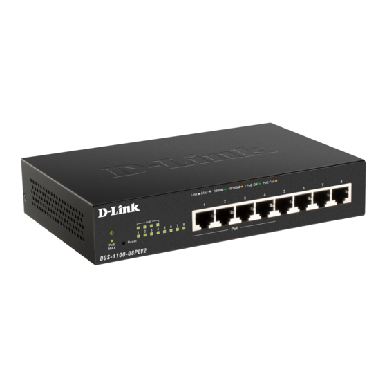
LED Indicators The Switches feature LED indicators for Power and Link/Act for each port. The following shows the LED indicators for the Switch along with an explanation of each indicator. Figure 1.3 - LED Indicators on DGS-1100-08PLV2 Location Indicator LED... - Page 8 1 Product Introduction D-Link Smart Managed Switch User Manual 7W, the PoE MAX LED will blink 5 seconds. When the power budget is using less Light off than 73W. Indicates there is a 1000 Mbps Solid Green connection on this port.
-
Page 9: Hardware Installation
Desktop or Shelf Installation DGS-1100-08PLV2 comes with a strip of four adhesive rubber pads that can be placed on the bottom of the device to prevent the device from damaging the desktop or shelf it is places on. To attach the rubber pads, simply remove them from the adhesive strip and stick one pad on each corner on the bottom panel of the Switch. - Page 10 2 Hardware Installation D-Link Smart Managed Switch User Manual Step 3: Hook the mounting keyholes on the back of the Switch onto the screws to secure the device to the wall. • Mounting on a wood wall Step 1: Drive the included screws into a wood wall.
-
Page 11: Getting Started
This chapter introduces the management interface of D-Link Smart Managed Switch. Management Options The D-Link Smart Managed Switch can be managed through any port on the device by using the web-based management interface, or the D-Link Network Assistant (DNA). Each switch must be assigned its own IP address, which is used for communication with the web-based management interface or a SNMP network manager. -
Page 12: Web-Based Management
D-Link Network Assistant (DNA) D-Link Network Assistant (DNA) is a program that is used to discover switches which are in the same Layer 2 network segment as your PC. You can download the DNA App from the D-Link official website. -
Page 13: Configuration
4 Configuration D-Link Smart Managed Switch User Manual Configuration The features and functions of the D-Link Smart Managed Switch can be configured through the web-based management interface. Web-based Management After a successful login you will see the screen below: Function Tree Main Configuration Window Figure 4.1 - Web-based Management... -
Page 14: Tool Bar > Save
4 Configuration D-Link Smart Managed Switch User Manual Tool Bar > Save The Save Menu provides Save Configuration and Save Log functions. Figure 4.2 - Save Menu Save Configuration By clicking Apply, the current device configuration will be saved on the device’s flash memory. -
Page 15: Configuration Backup And Restore
4 Configuration D-Link Smart Managed Switch User Manual Figure 4.7 - Tools > Firmware Backup and Upgrade Click Backup to save the firmware to your disk. Click Upgrade to upgrade the firmware. Figure 4.8 - Tools > Firmware Backup and Upgrade - Confirm Click OK to see the countdown timer window. -
Page 16: Tool Bar > Help
Tool Bar > Help The Help Menu provides two ways of online support. D-Link Support Site leads to the D-Link website where you can find online resources such as updated firmware images. User Guide can offer an immediate reference for the feature definition or configuration guide. -
Page 17: System > System Information Settings > System Information
4 Configuration D-Link Smart Managed Switch User Manual Figure 4.14 - Device Information System > System Information Settings > System Information The System Information allows the user to configure the basic system information of the Switch. By entering the system information, the Switch can more easily be recognized from other Smart Managed devices on the network. -
Page 18: System > Port Configuration > Port Settings
4 Configuration D-Link Smart Managed Switch User Manual The fields that can be configured are described below: Item Description There are two ways for the Switch to obtain an IP address: Static and DHCP (Dynamic Host Configuration Protocol). When using the static mode, the IP Address, Mask, and Gateway can be manually configured. -
Page 19: System > Port Configuration > Jumbo Frame
System > Port Configuration > Jumbo Frame D-Link Smart Managed Switches support jumbo frames (frames larger than the Ethernet frame size of 1536 bytes) of up to 9216 bytes (tagged). This function is disabled by default. Click Enabled and Apply to turn on the jumbo frame support. -
Page 20: System > Poe > Poe Configuration
4 Configuration D-Link Smart Managed Switch User Manual • Deny low priority port: The port with the lower priority will be shut down to allow the higher priority port to power up. Legacy Support Specify to enable or disable detecting legacy PDs signal. -
Page 21: System > Poe > Pd Alive
4 Configuration D-Link Smart Managed Switch User Manual Figure 4.20 - System > PoE > PoE Configuration The fields that can be configured are described below: Item Description From Port / To Port Specify the PoE function of a port or ports. -
Page 22: Management > Password Access Control
4 Configuration D-Link Smart Managed Switch User Manual Figure 4.21 - System > PoE > PD Alive The fields that can be configured are described below: Item Description From Port / To Port Specifies a port or ports. PD Alive State Select enable or disable PD Alive function. -
Page 23: Management > Snmp > Snmp Community Table Settings
4 Configuration D-Link Smart Managed Switch User Manual read and modify the settings of gateways, routers, switches, and other networks. Use SNMP to configure system features for proper operation, monitor performance and detect potential problems in the Switch or LAN. -
Page 24: Management > Snmp > Snmp Host Settings
Table 4.10 Click Apply to make the configurations take effect. Management > D-Link Discovery Protocol For devices that support the D-Link Discovery Protocol (DDP), this window allows users to enable or disable DDP, and configure the DDP packet report timer. -
Page 25: L2 Features > Fdb > Static Fdb > Unicast Static Fdb
Item Description D-Link discovery Specify to enable or disable the D-Link discovery protocol feature of Protocol State the Switch. Configure the report timer of the D-Link Discover Protocol in seconds. The values are 30, 60, 90, 120 or Never. The default is Report Timer Never. -
Page 26: L2 Features > Fdb > Mac Address Table Settings
4 Configuration D-Link Smart Managed Switch User Manual Figure 4. 28 - L2 Features > FDB > Static FDB > Multicast Static FDB The fields that can be configured are described below: Item Description From Port / To Port Select the appropriate port range used for the configuration. -
Page 27: L2 Features > Fdb > Mac Address Table
4 Configuration D-Link Smart Managed Switch User Manual L2 Features > FDB > MAC Address Table This window is used to view the entries listed in the MAC address table. Figure 4.30 - L2 Features > FDB > MAC Address Table... - Page 28 4 Configuration D-Link Smart Managed Switch User Manual VLANs can be easily organized to reflect department groups (such as R&D, Marketing), usage groups (such as e-mail), or multicast groups (multimedia applications such as video conferencing), and therefore help to simplify network management by allowing users to move devices to a new VLAN without having to change any physical connections.
-
Page 29: L2 Features > Vlan > Port-Based Vlan
4 Configuration D-Link Smart Managed Switch User Manual Figure 4.34 - L2 Features > VLAN > 802.1Q VLAN – Edit VID Click Apply to make the configurations take effect. Click Previous Page to discard any changed made and return to the previous page. -
Page 30: L2 Features > Vlan > Management Vlan
4 Configuration D-Link Smart Managed Switch User Manual To create a new Port-Based VLAN group, click Add VLAN and the following will be displayed: Figure 4.37 - L2 Features > VLAN > Port-Based VLAN - Add Enter the VLAN Name and select the Member port to be created. -
Page 31: L2 Features > Vlan > Surveillance Vlan
L2 Features > VLAN > Surveillance VLAN Surveillance VLAN is a feature that allows you to place the video traffic from D-Link IP cameras to an assigned VLAN to enhance the IP surveillance service. With a higher priority and individual VLAN, the quality and the security of surveillance traffic are guaranteed. -
Page 32: L2 Features > Vlan > Voice Vlan
L2 Features > VLAN > Voice VLAN Voice VLAN is a feature that allows you to place the voice traffic from D-Link IP phones to an assigned VLAN to enhance the IP voice service. With a higher priority and individual VLAN, the quality and the security of voice traffic are guaranteed. - Page 33 4 Configuration D-Link Smart Managed Switch User Manual Figure 4.41 - L2 Features > VLAN > Voice VLAN The fields that can be configured are described below: Item Description Voice VLAN Global Settings Voice VLAN Specify to enable or disable the Voice VLAN function.
-
Page 34: L2 Features > Spanning Tree > Stp Global Settings
4 Configuration D-Link Smart Managed Switch User Manual L2 Features > Spanning Tree > STP Global Settings The Switch implements two versions of the Spanning Tree Protocol: Rapid Spanning Tree Protocol (RSTP) as defined by IEEE 802.1w, a version compatible with the IEEE 802.1D STP. RSTP can operate with legacy equipment implementing IEEE 802.1D, however the advantages of using RSTP will be lost. -
Page 35: L2 Features > Loopback Detection
4 Configuration D-Link Smart Managed Switch User Manual Figure 4.43 - L2 Features > Spanning Tree > STP Port Settings The fields that can be configured are described below: Item Description Select the range of ports to be included in the spanning tree port From Port / To Port group. -
Page 36: L2 Features > Link Aggregation
4 Configuration D-Link Smart Managed Switch User Manual Figure 4.44 - L2 Features > Loopback Detection Settings The fields that can be configured are described below: Item Description Loopback Detection Global Settings Specify to enable or disable loopback detection function. The Loopback Detection default is Disabled. -
Page 37: L2 Features > L2 Multicast Control > Igmp Snooping > Igmp Snooping Settings
4 Configuration D-Link Smart Managed Switch User Manual Figure 4.45 - L2 Features > Link Aggregation The fields that can be configured f are described below: Item Description Link Aggregation Global Settings Link Aggregation Specify to enable or disable the Link Aggregation function. -
Page 38: L2 Features > L2 Multicast Control > Igmp Snooping > Igmp Snooping Group Settings
4 Configuration D-Link Smart Managed Switch User Manual Click Apply to make the configuration take effect. L2 Features > L2 Multicast Control > IGMP Snooping > IGMP Snooping Group Settings The IGMP Snooping Group Settings window allows user to configure IGMP snooping static groups and display IGMP snooping groups on the Switch. - Page 39 The fields that can be configured are described below: Item Description Global Settings D-Link Smart Managed Switch allows the user to prioritize the traffic based on the 802.1p priority in the VLAN tag or the Select QoS mode DSCP (Differentiated Services Code Point) priority in the IP header.
-
Page 40: Qos > Port Rate Limiting
4 Configuration D-Link Smart Managed Switch User Manual priority classes. IEEE 802.1p Default Priority Settings From Port / To Port Specify a range of ports to be configured. Defines the priority level for the corresponding port. The priority Priority range is between 0 and 7 with 0 being assigned to the lowest priority and 7 assigned to the highest. -
Page 41: Security > Storm Control
4 Configuration D-Link Smart Managed Switch User Manual Figure 4.51 - Security > Traffic Segmentation The fields that can be configured are described below: Item Description From Port / To Port Specify a range of ports to be configured as sources ports. -
Page 42: Oam > Cable Diagnostics
4 Configuration D-Link Smart Managed Switch User Manual Ports can be locked to prevent users from modifying the MAC address forwarding table. Locking ports also prevents additional MAC addresses from being learned. Figure 4.53 - Security > Port Security The fields that can be configured are described below:... -
Page 43: Monitoring > Statistics > Port Counters
4 Configuration D-Link Smart Managed Switch User Manual Figure 4.55 - Cable Diagnostics - Results The information that can be viewed is described below: Item Description The description of the cable diagnostic results. • OK means the cable is in good condition. -
Page 44: Green > Eee
4 Configuration D-Link Smart Managed Switch User Manual Figure 4.57 - Monitoring > Mirroring Settings The fields that can be configured are described below: Item Description Specify to enable or disable the mirroring function of the Mirroring Settings Switch. Specify the destination where the data will be mirrored too. -
Page 45: Ethernet Technology
Ethernet Technology D-Link Smart Managed Switch User Manual Ethernet Technology This chapter will describe the features of the D-Link Smart Managed Switch and provide some background information about Ethernet/Fast Ethernet/Gigabit Ethernet switching technology. Gigabit Ethernet Technology Gigabit Ethernet is an extension of IEEE 802.3 Ethernet utilizing the same packet structure, format, and support for CSMA/CD protocol, full duplex, and management objects, but with a tenfold increase in theoretical throughput of over 100-Mbps Fast Ethernet and a hundredfold increase over 10-Mbps Ethernet. -
Page 46: Technical Specifications
Technical Specifications D-Link Smart Managed Switch User Manual Technical Specifications Key Components / Performance Switching Capacity 16 Gbps Max. Forwarding Rate 11.9 Mpps Forwarding Mode Store and Forward Packet Buffer Size 1.5 MB Flash Memory 2 MB Port Functions Standard Compliance: •... -
Page 47: Regulatory Statements
Regulatory Statements D-Link Smart Managed Switch User Manual Regulatory Statements CE Mark Warning: This is a Class B product. In a domestic environment, this product may cause radio interference, in which case the user may be required to take adequate measures. - Page 48 Regulatory Statements D-Link Smart Managed Switch User Manual • Do not spill food or liquid on your product and never push any objects into the openings of your product. • Do not use this product near water, areas with high humidity, or condensation unless the product is specifically rated for outdoor application.
- Page 49 Regulatory Statements D-Link Smart Managed Switch User Manual • No utilice este producto cerca del agua, en zonas con humedad o condensación elevadas a menos que el producto esté clasificado específicamente para aplicación en exteriores. • Mantenga el producto alejado de los radiadores y de otras fuentes de calor.
- Page 50 D-Link recommends that you always switch off or unplug your D-Link products when they are not in use. By doing so you will help to save energy and reduce CO2 emissions.
- Page 51 D-Link e l'ambiente D-Link cerca da sempre di ridurre l'impatto ambientale dei propri stabilimenti e dei propri prodotti. Allo scopo di ridurre al minimo tale impatto, D-Link progetta e realizza i propri prodotti in modo che rispettino il più...
- Page 52 D-Link raadt aan om steeds uw D-Link producten uit te schakelen of uit de stekker te halen wanneer u ze niet gebruikt. Door dit te doen bespaart u energie en beperkt u de CO2-emissies.
- Page 53 životní prostředí i lidské zdraví. D-Link a životní prostředí Ve společnosti D-Link jsme si vědomi vlivu našich provozů a výrobků na životní prostředí a snažíme se o minimalizaci těchto vlivů. Proto své výrobky navrhujeme a vyrábíme tak, aby byly co nejekologičtější, a ve výrobcích i obalech používáme recyklovatelné...
- Page 54 å gjenvinne produktet og forpakningen hjelper du å verne miljøet og beskytte folks helse. D-Link og miljøet Hos D-Link forstår vi oss på og er forpliktet til å minske innvirkningen som vår drift og våre produkter kan ha på miljøet. For å minimalisere denne innvirkningen designer og lager D-Link produkter som er så...
- Page 55 På D-Link förstår vi och är fast beslutna att minska den påverkan våra verksamheter och produkter kan ha på miljön. För att minska denna påverkan utformar och bygger D-Link sina produkter för att de ska vara så miljövänliga som möjligt, genom att använda återvinningsbara material med låg gifthalt i både produkter och förpackningar.