
Related Manuals for D-Link DGS-1100-05PDV2


Summary of Contents for D-Link DGS-1100-05PDV2
- Page 1 D G S - 1 1 0 0 - 0 5 V 2 / 0 5 P D V 2 / 0 8 V 2 / 0 8 P V 2 Ma n u a l S MA R T MA N A G E D S WI T C H V e r .
-
Page 2: Table Of Contents
System > System Information Settings > System Information ..............15 System > System Information Settings > IPv4 Interface ................16 System > Port configuration > Port Settings .................... 16 System > Port Configuration > Jumbo Frame ..................17 System > PoE > PoE System (DGS-1100-05PDV2/08PV2 only) ............17... -
Page 3: Table Of Contents
Table of Contents D-Link Smart Managed Switch User Manual System > PoE > PoE Configuration (DGS-1100-05PDV2/08PV2 only) ..........18 System > PoE > PD Alive (DGS-1100-05PDV2/08PV2 only) ..............20 Management > Password Access Control ....................20 Management > SNMP > SNMP Global Settings ..................21 Management >... -
Page 4: About This Guide
Reproduction in any manner whatsoever without the written permission of D-Link Corporation is strictly forbidden. Trademarks used in this text: D-Link and the D-LINK logo are trademarks of D-Link Corporation; Microsoft and Windows are registered trademarks of Microsoft Corporation. Other trademarks and trade names may be used in this document to refer to either the entities claiming the marks and names or their products. -
Page 5: Product Introduction
D-Link Smart Managed Switch User Manual Product Introduction Thank you and congratulations on the purchase of your new D-Link Smart Managed Switch. D-Link's next generation Smart Managed switch series blends plug-and-play simplicity with exceptional value and reliability for small and medium-sized business (SMB) networking. All models are housed in a robust metal case with easy-to-view front panel diagnostic LEDs. -
Page 6: Rear Panel
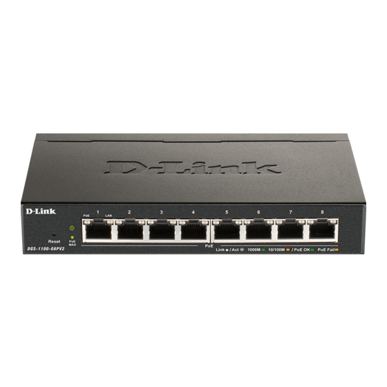
2-Port 10/100/1000Mbps PoE and 3-Port 10/100/1000Mbps with 1 PD port Smart Managed Switch. Front Panel Figure 1.3 – DGS-1100-05PDV2 Front Panel Power LED: The Power LED lights up when the Switch is connected to a power source. If the Power LED is Blinking, PoE Pass Through is Off. -
Page 7: Rear Panel
Cet appareil est fourni par POE via un ITE répertorié UL. Rear Panel Figure 1.4 – DGS-1100-05PDV2 Rear Panel Power: Use RJ45 to connect the PD port (port 5) and Power over Ethernet Adapter Kit. Kensington Lock: This is used to attach a physical Kensington security lock. -
Page 8: Dgs-1100-08Pv2
1 Product Introduction D-Link Smart Managed Switch User Manual Power: Input for a 5V/1A AC adapter. Reset: Press the Reset button for 1 to 5 seconds to reboot the Switch. Press the Reset button for 6 to10 seconds to reset the Switch back to the default settings. The LED will light up solid amber for 2 seconds. -
Page 9: Rear Panel
1 Product Introduction D-Link Smart Managed Switch User Manual CAUTION: The equipment power supply cord shall be connected to a socket-outlet with earthing connection. Le cordon d'alimentation de l'équipement doit être branché sur une prise de courant dotée d'une connexion à la terre. - Page 10 1 Product Introduction D-Link Smart Managed Switch User Manual Indicates there is a 10/100 Mbps Solid Amber connection on this port. Blinking Indicates data is being processed on Amber this port at 10/100 Mbps. Indicates there is no active link on this Light off port.
-
Page 11: Hardware Installation
2 Hardware Installation D-Link Smart Managed Switch User Manual Hardware Installation This chapter provides unpacking installation information your D-Link DGS-1100- 05V2/05PDV2/08V2/08PV2 Smart Managed Switch. Step 1: Unpacking Open the shipping carton and carefully unpack its contents. Please consult the packing list below to make sure all items are present and undamaged. - Page 12 2 Hardware Installation D-Link Smart Managed Switch User Manual Step 2. Hook the mounting keyholes on the back of the Switch onto the screws to secure the device to the wall. Figure 2.2 – Wall mount installation Metal screw (M7 type; Length 16 mm, Number of screws *2) for DGS-1100-05V2/05PDV2/08V2/08PV2...
-
Page 13: Getting Started
This chapter introduces the management interface of D-Link Smart Managed Switch. Management Options The D-Link Smart Managed Switch can be managed through any port on the device by using the web-based management interface, or the D-Link Network Assistant (DNA). Each switch must be assigned its own IP address, which is used for communication with the web-based management interface or a SNMP network manager. -
Page 14: Web-Based Management
D-Link Network Assistant (DNA) D-Link Network Assistant (DNA) is a program that is used to discover switches which are in the same Layer 2 network segment as your PC. You can download the DNA App from the Chrome web store and install it in a Chrome web browser. -
Page 15: Configuration
Logout button first, then it will be seen as an abnormal exit and the login session will still be occupied. By clicking on the D-Link logo in the upper-left corner of the screen you will be redirected to the local D-Link website. -
Page 16: Tool Bar > Save Menu
4 Configuration D-Link Smart Managed Switch User Manual Tool Bar > Save Menu The Save Menu provides Save Configuration and Save Log functions. Figure 4.2 – Save Menu Save Configuration By clicking Apply, the current device configuration will be saved on the device’s flash memory. -
Page 17: Configuration Backup And Restore
Tool Bar > Online Help The Online Help provides two ways of online support: D-Link Support Site will lead you to the D-Link website where you can find online resources such as updated firmware images; User Guide can offer an immediate reference for the feature definition or configuration guide. -
Page 18: Device Information
4 Configuration D-Link Smart Managed Switch User Manual Figure 4.11 –Function Tree Device Information The Device Information provides an overview of the Switch, including essential information such as firmware and hardware information, and IP address. Figure 4.12 – Device Information System >... -
Page 19: System > System Information Settings > Ipv4 Interface
4 Configuration D-Link Smart Managed Switch User Manual System Location Specify the system location of the Switch. System Contact Specify the system contact of the Switch. The Web Session Timeout controls the idle time-out period for security purposes, when there is no activity in the web Web Session Timeout interface within the specified time-out period. -
Page 20: System > Port Configuration > Jumbo Frame
System > Port Configuration > Jumbo Frame D-Link Smart Managed Switches support jumbo frames (frames larger than the Ethernet frame size of 1536 bytes) of up to 9216 bytes (tagged). This function is disabled by default. Select Enabled then click Apply to turn on the jumbo frame support. -
Page 21: System > Poe > Poe Configuration (Dgs-1100-05Pdv2/08Pv2 Only)
Click Apply to make the configurations take effect. System > PoE > PoE Configuration (DGS-1100-05PDV2/08PV2 only) The DGS-1100-05PDV2/08PV2 support Power over Ethernet (PoE) as defined by the IEEE specification. The PoE port specification is listed in the table below: Model Name... - Page 22 Current (mA), Classification, Port Status. You can select From Port / To Port to control the PoE functions of a port. The DGS-1100-05PDV2/08PV2 will auto disable the ports if port current is over 375mA in 802.3af mode or 625mA in pre-802.3at mode.
-
Page 23: System > Poe > Pd Alive (Dgs-1100-05Pdv2/08Pv2 Only)
500ms. If the PD is still not powering on, please contact the vendor of your device for support. System > PoE > PD Alive (DGS-1100-05PDV2/08PV2 only) PD Alive function is a mechanism to detect PD host periodically. Once the PD host cannot be reached within the interval configured by administrator, then action would be executed. -
Page 24: Management > Snmp > Snmp Global Settings
4 Configuration D-Link Smart Managed Switch User Manual The fields that can be configured for Password Access Control are described below: Item Description Old Password Enter the old password of the Switch. New Password Enter the new password of the Switch. -
Page 25: Management > Snmp > Snmp Community Table Settings
4 Configuration D-Link Smart Managed Switch User Manual Check this feature to have client devices send an SNMP Warmstart notification to the management station when performing a warm start. Table 4.8 Click Apply to make the configurations take effect. Management > SNMP > SNMP Community Table Settings This SNMP Community Table Settings page is used to create an SNMP community string to define the relationship between the SNMP manager and an agent. -
Page 26: Management > D-Link Discovery Protocol
Click Apply to make the configurations take effect. Management > D-Link Discovery Protocol For devices that support the D-Link Discovery Protocol (DDP), this page allows users to enable or disable DDP, and configure the DDP packet report timer. Figure 4.24 – Management > D-Link Discovery Protocol... -
Page 27: L2 Features > Fdb > Static Fdb > Multicast Static Fdb
4 Configuration D-Link Smart Managed Switch User Manual L2 Features > FDB > Static FDB > Multicast Static FDB The Multicast Static FDB page allows user to view and configure the static multicast forwarding settings on the Switch. Figure 4.26 – L2 Features > FDB > Static FDB > Multicast Static FDB... -
Page 28: L2 Features > Fdb > Mac Address Table
4 Configuration D-Link Smart Managed Switch User Manual L2 Features > FDB > MAC Address Table The MAC Address Table page allows user to view the entries listed in the MAC address table. Figure 4.28 – L2 Features > FDB > MAC Address Table... -
Page 29: L2 Features > Vlan > Port-Based Vlan
4 Configuration D-Link Smart Managed Switch User Manual The fields that can be configured for 802.1Q VLAN are described below: Item Description Enter the VID to be created. VLAN Name Enter the VLAN name for the VID to be created. -
Page 30: L2 Features > Vlan > Management Vlan
4 Configuration D-Link Smart Managed Switch User Manual Figure 4.33 – L2 Features > VLAN > Port-Based VLAN - Enabled Enter the VLAN Name and select the Member port to be created. Click Apply to make the configurations take effect. -
Page 31: L2 Features > Vlan > Surveillance Vlan
L2 Features > VLAN > Surveillance VLAN Surveillance VLAN is a feature that allows you to place the video traffic from D-Link IP cameras to an assigned VLAN to enhance the IP surveillance service. With a higher priority and individual VLAN, the quality and the security of surveillance traffic are guaranteed. -
Page 32: L2 Features > Vlan > Voice Vlan
L2 Features > VLAN > Voice VLAN Voice VLAN is a feature that allows you to place the voice traffic from D-Link IP phones to an assigned VLAN to enhance the IP voice service. With a higher priority and individual VLAN, the quality and the security of voice traffic are guaranteed. -
Page 33: L2 Features > Spanning Tree > Stp Global Settings
4 Configuration D-Link Smart Managed Switch User Manual the Voice VLAN rules. Table 4.20 Below is a list of the pre-defined voice OUI’s. These cannot be used as a user defined OUI. Vendor Mnemonic Name 00:E0:BB 3COM 3com 00:03:6B Cisco... -
Page 34: L2 Features > Spanning Tree > Stp Port Settings
4 Configuration D-Link Smart Managed Switch User Manual and STP. STP Traps STP New Root Trap Select to enable or disable the STP new root trap option. STP Topology Change Select to enable or disable the STP topology change trap Traps option. -
Page 35: L2 Features > Loopback Detection
4 Configuration D-Link Smart Managed Switch User Manual change to the forwarding state. In the Edge mode, the port will directly change to the spanning-tree forwarding state when a link-up occurs without waiting for the forward-time delay. If the interface receives a BPDU later, its operation state changes to the non-port-fast state. -
Page 36: L2 Features > Link Aggregation
4 Configuration D-Link Smart Managed Switch User Manual L2 Features > Link Aggregation The Link Aggregation function enables the combining of two or more ports together to increase bandwidth. Each Link Aggregation group supports a maximum of four ports. Figure 4.41 – L2 Features > Link Aggregation... -
Page 37: L2 Features > L2 Multicast Control > Igmp Snooping > Igmp Snooping Group Settings
4 Configuration D-Link Smart Managed Switch User Manual Figure 4.42 – L2 Features > L2 Multicast Control > IGMP Snooping > IGMP Snooping Settings The fields that can be configured for are described below: Item Description Specify to enable or disable the IGMP Snooping function of the IGMP Snooping Switch. -
Page 38: Qos > Port Rate Limiting
The fields that can be configured are described below: Item Description Global Settings D-Link Smart Managed Switch allows the user to prioritize the traffic based on the 802.1p priority in the VLAN tag or the Select QoS mode DSCP (Differentiated Services Code Point) priority in the IP header. -
Page 39: Security > Traffic Segmentation
4 Configuration D-Link Smart Managed Switch User Manual The fields that can be configured for Port Rate Limiting are described below: Item Description From Port / To Port Specify a range of ports to be configured. Select the direction option. Options to choose from are: Input: This configures the transfer speed limit for ingress ... -
Page 40: Security > Port Security
4 Configuration D-Link Smart Managed Switch User Manual Storm Control Status Specify to enable or disable the storm control function. Specify the type of controlled packets, Options are Broadcast Storm Control Only, Multicast & Broadcast, and Multicast & Broadcast &... -
Page 41: Monitoring > Statistics > Port Counters
4 Configuration D-Link Smart Managed Switch User Manual Select a port and then click the Test Now button to start the diagnosis. The results will be displayed below: Figure 4.50 - OAM > Cable Diagnostics - results The information that can be viewed is described below:... -
Page 42: Green > Eee
4 Configuration D-Link Smart Managed Switch User Manual Figure 4.52 – Monitoring > Mirroring Settings The fields that can be configured for Mirroring Settings are described below: Item Description Specify to enable or disable the mirroring function of the Mirroring Settings Switch. -
Page 43: Ethernet Technology
Ethernet Technology D-Link Smart Managed Switch User Manual Ethernet Technology This chapter will describe the features of the D-Link Smart Managed Switch and provide some background information about Ethernet/Fast Ethernet/Gigabit Ethernet switching technology. Gigabit Ethernet Technology Gigabit Ethernet is an extension of IEEE 802.3 Ethernet utilizing the same packet structure, format, and support for CSMA/CD protocol, full duplex, and management objects, but with a tenfold increase in theoretical throughput of over 100-Mbps Fast Ethernet and a hundredfold increase over 10-Mbps Ethernet. -
Page 44: Poe Passthrough
D-Link Smart Managed Switch User Manual PoE Passthrough The DGS-1100-05PDV2 is a PoE passthrough switch that is powered through a Powered Device (PD) port (Port 5) and can also provide PoE power (Port 1~2) to connected devices. This means that power cords will become a thing of the past with the flexibility to place the switch on the ceiling, wall, or other places where power outlets may not be available. -
Page 45: Technical Specifications
DGS-1100-08V2: 0.34 kg DGS-1100-08PV2: 0.433 kg DGS-1100-05V2/08V2/08PV2: AC:100 ~ 240 V Power Supply DGS-1100-05PDV2: NO external power supply, PoE input only DGS-1100-05V2: Maximum – AC 3.42 W Standby – AC 1.39 W DGS-1100-05PDV2: Maximum – AC 24.084 W Standby – 1.728 W... - Page 46 Technical Specifications D-Link Smart Managed Switch User Manual Operation Temperature 0 ~ 40 °C Storage Temperature - 40 ~ 70 °C Operation Humidity 0%~90% RH Storage Humidity 0%~95% RH EMI Certifications CE, FCC, ITE, RCM, VCCI, BSMI Safety Certifications cUL, CB, BSMI...
-
Page 47: Regulatory Statements
Regulatory Statements D-Link Smart Managed Switch User Manual Regulatory Statements CE Mark Warning: This is a Class B product. In a domestic environment, this product may cause radio interference, in which case the user may be required to take adequate measures. - Page 48 Regulatory Statements D-Link Smart Managed Switch User Manual The following general safety guidelines are provided to help ensure your own personal safety and protect your product from potential damage. Remember to consult the product user instructions for more details. •...
- Page 49 Regulatory Statements D-Link Smart Managed Switch User Manual • La electricidad estática puede resultar nociva para los componentes electrónicos. Descargue la electricidad estática de su cuerpo (p. ej., tocando algún metal sin revestimiento conectado a tierra) antes de tocar el producto.
- Page 50 D-Link recommends that you always switch off or unplug your D-Link products when they are not in use. By doing so you will help to save energy and reduce CO2 emissions.
- Page 51 Chez D-Link, nous sommes conscients de l'impact de nos opérations et produits sur l'environnement et nous engageons à le réduire. Pour limiter cet impact, D-Link conçoit et fabrique ses produits de manière aussi écologique que possible, en utilisant des matériaux recyclables et faiblement toxiques, tant dans ses produits que ses emballages.
- Page 52 D-Link raadt aan om steeds uw D-Link producten uit te schakelen of uit de stekker te halen wanneer u ze niet gebruikt. Door dit te doen bespaart u energie en beperkt u de CO2-emissies.
- Page 53 životní prostředí i lidské zdraví. D-Link a životní prostředí Ve společnosti D-Link jsme si vědomi vlivu našich provozů a výrobků na životní prostředí a snažíme se o minimalizaci těchto vlivů. Proto své výrobky navrhujeme a vyrábíme tak, aby byly co nejekologičtější, a ve výrobcích i obalech používáme recyklovatelné...
- Page 54 å gjenvinne produktet og forpakningen hjelper du å verne miljøet og beskytte folks helse. D-Link og miljøet Hos D-Link forstår vi oss på og er forpliktet til å minske innvirkningen som vår drift og våre produkter kan ha på miljøet. For å minimalisere denne innvirkningen designer og lager D-Link produkter som er så...
- Page 55 På D-Link förstår vi och är fast beslutna att minska den påverkan våra verksamheter och produkter kan ha på miljön. För att minska denna påverkan utformar och bygger D-Link sina produkter för att de ska vara så miljövänliga som möjligt, genom att använda återvinningsbara material med låg gifthalt i både produkter och förpackningar.