Table of Contents
Advertisement
Quick Links
Advertisement
Table of Contents

Related Manuals for Siemens 9200


Summary of Contents for Siemens 9200
- Page 1 9200 Power Meter Installation & Operation Guide...
- Page 3 Static Trip III, Wisdom, and WinPM are trademark, Sensitrip and Sentron are registered trade- marks of Siemens Energy & Automation, Inc. SIEMENS is a registered trademark and Windows is a trademark of Microsoft Corporation. ION is a registered trademark of Power Measurement Ltd.
-
Page 4: Standards Compliance
0.6. Connection to the 9200 internal modem should be made via an FCC Part 68 compliant telephone cord (not supplied). The 9200 cannot be used on a public coin phone service or party line services. Network Compatibility Notice for the Internal Modem The internal modem in meters equipped with this option is compatible with the telephone systems of most countries in the world, with the exception of Australia and New Zealand. - Page 5 For more information on the different meter options, refer to the Options Card Retrofit Instructions on the Siemens web site The term “basic meter” refers to Integrated or TRAN models with a standard Options Card (real-time voltage and current measurements).
-
Page 6: Before You Begin
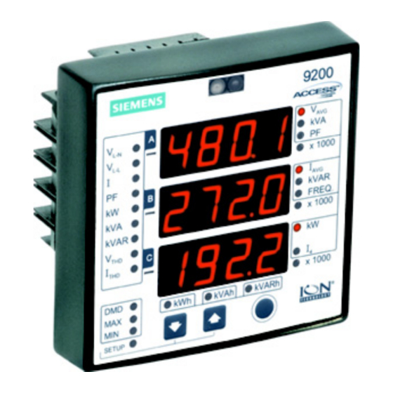
Quick Install This section can be used by a licensed electrician to install and perform basic meter setup. For more detailed meter setup and use instructions, see the “Using the Meter” section in this guide. Before You Begin Familiarize yourself with the steps in this Quick Install section and read the safety precautions presented on the “Installation Considerations”... - Page 7 ANGER Do not power up the meter until the current and voltage wiring is completed. Recommended Tools #1 and #2 Phillips screwdrivers Precision flat-head screwdriver Wire cutters / stripper Meter Overview Front of Meter Rear of Meter Voltage Inputs Phase COM1 System D2: Form A...
- Page 8 Unit Dimensions Integrated Model Dimensions 110 mm 40 mm (4.30”) (1.58”) 91 mm 110 mm (3.58”) (4.30”) 25 mm (.99”) TRAN Model Dimensions 109 mm 69 mm (4.27”) (2.72”) 86 mm (3.37”) 109 mm (4.27”) 85 mm 86 mm (3.37”) (3.37”) 1 mm 43”)
- Page 9 Step 1: Assemble the Meter Insert the Options Card in the slot at the back of the meter, then firmly slide the card up and into place. Insert the power supply’s plug-in connector into the meter’s plug-in port. Attach the power supply by tightening the captive screws using a #1 Phillips screwdriver.
- Page 10 Mounting the Integrated Model Fit the meter into the cutout [DIN 96 standard or ANSI 4”]. Insert each screw through the drilled hole on the mounting surface and into its corresponding metal insert located on the back of the meter. Note that the DIN 96 cutout does not require drilled holes.
- Page 11 Mounting the RMD (if equipped) The Remote Modular Display (RMD) is a product option for 9200 TRAN meters. The RMD can be mounted in either a standard DIN or ANSI cutout. 9200 RMD Retrofit Instructions See the for more information.
- Page 12 Typical Form A Digital Output Use Select an MOV (metal oxide varistor) or clamping diode that ensures the output terminals do not receive voltage greater than 350 V peak during switching. Step 5: Wire the Voltage and Current Inputs Voltage Input Specifications Connector Type Ring or split-ring, or bare wire.
- Page 13 AUTION In cases where PTs are required, the secondaries should be fused. Current Input Specifications Connector Type Ring or split-ring, or bare wire. Wire 14 to 12 AWG (2.1mm to 3.3mm Inputs I1, I2, I3 10 A RMS (+ 20% maximum, 300 V RMS Rated Inputs to ground) Installation category III (Distribution).
- Page 14 4-Wire Wye, 3-Element Direct Connection 120° 0° 0° PF angle = 0.9 (25° Lag) 400 VAC L-N / 690 VAC L-L max. Volts Mode = 4W-Wye 4-Wire Wye, 3-Element, 3 PT, 3 CT 120° 0° 0° PF angle = 0.9 (25° Lag) Use PTs for voltages over 400 VAC L-N / 690 VAC L-L Wye (Star) wiring for PT primaries and secondaries.
- Page 15 3-Wire Delta, 2½-Element, 2 PT, 3 CT 0° 0° PF angle = 0.9 (25° Lag) Use PTs for voltages over 690 VAC L-L Volts Mode = Delta 3-Wire Delta, 2-Element, 2 PT, 2 CT. 0° 0° PF angle = 0.9 (25° Lag) Use PTs for voltages over 690 VAC L-L Volts Mode = Delta 3 Wire Delta Direct Connection...
- Page 16 3-Wire Grounded Wye, 3-Element Direct 120° 0° 0° PF angle = 0.9 (25° Lag) The configuration requires that the transformer secondary star-point is grounded. The phase-to-ground voltages must be within the meter’s range. Volts Mode = 4W-Wye Single Phase Connection Diagram 0°...
-
Page 17: Power Supply Specifications
Modbus protocol implementation details. Step 7: Wire the Power Supply Power supply connections differ depending on the power supply option used. For more detailed information on how to connect your 9200 power supply, 9200 Power Supply Retrofit Instructions. refer to the... - Page 18 Power Supply Connections Power Supply Connector Type Wire 18 to 14 AWG Standard AC / DC power supply Captured wire (0.8mm to 2.1mm 18 to 14 AWG Low Voltage DC power supply Captured wire (0.8mm to 2.1mm Ring 18 to 14 AWG 480 V power supply Split-ring (0.8mm...
- Page 19 Configurable Settings String Description Range (Values) Default 4W (4-Wire WYE) tYPE dELt (Delta) 2W (Single Phase) Delta Volts Mode dEM (Demonstration) Direct 3W (3-Wire WYE) dELd (Delta Direct) PT1 (Primary) 1 to (65.53 x 1000 LED) P P S S 1 (x 1);...
- Page 20 String Description Range (Values) Default 0.001, 0.01, 0.1, 1, 10, 100, Voltage Scale 1000 0.001, 0.01, 0.1, 1, 10, 100, Current Scale 1000 0.001, 0.01, 0.1, 1, 10, 100, Power Scale 1000 0.001, 0.01, 0.1, 1, 10, 100, Neutral Scale 1000 (k)Wh Del., (k)VAh, (k)VARh Del., out1...
- Page 21 3-position power supply connector flashes once per second. LED flashes once per second when the TRAN is operating If your meter is not operating properly, consult the Siemens Support web site at http://pwrm.com/support/ for troubleshooting tips and frequently asked questions.
-
Page 22: Display Mode
Using the Meter With the meter front panel, you can view parameter values; configure parameters; perform demand resets; perform LED checks; and view meter information. Each of these functions can be accomplished by pressing the Up, Down, and Enter buttons on the front panel. These button actions achieve different results according to the mode that the meter is in: Display mode (default): view parameter measurements Reset mode: reset demand measurements... -
Page 23: Reset Mode
Button Functions in Display Mode Mode Button Function Display View the previous parameter value. Mode View the next parameter value. Display mode is the meter Move from one measurement group to the next measurement default. group. Reset Mode In Reset mode, you can perform a Current (Maximum) Demand reset, a Power (Maximum) Demand reset, or an Energy reset. - Page 24 Button Functions in Configuration Select Mode Mode Button Function Move to the previous parameter Configuration Select Mode configuration screen. Move to the next parameter configuration ENTER Configuration Select mode screen. by pressing the Up and Down buttons at the same time and Enter Configuration Edit mode to configure holding for 2 seconds.
- Page 25 Configurable meter settings are listed in “Configurable Settings” on page 19. Configuration Software To monitor, configure, or perform energy resets on your meter, Siemens offers a number of software alternatives. For information on the availability of configuration and system software, refer to our web site at www.sea.siemens.com/access, or contact Customer Service.
- Page 26 Standard Measurements and Enhanced Packages 1 & 2 Standard Enhanced Pkg. 1 Enhanced Pkg. 2 Parameter Display Pulse Display Pulse Display Pulse Volts L-N Avg Volts L-N Per Phase Volts L-L Avg Volts L-L Per Phase Current Avg Current Per Phase Current Neutral Power Total Power Per Phase...
- Page 28 For More Information Visit 3333 Old Milton Parkway sales/salesoffices.html www.sea.siemens.com/access Alpharetta, GA 30005 © Siemens Energy & Automation, Inc. Windows is a trademark and Order No. PMIM-9201E-0603 PDF 0800 Printed in the U.S.A. Microsoft is a registered trademark Siemens is a registered trademark of of Microsoft Corporation.