Table of Contents
Advertisement
Advertisement
Table of Contents

Related Manuals for Siemens 9200


Summary of Contents for Siemens 9200
- Page 1 9200 Power Meter 9200 Features Guide...
-
Page 3: Table Of Contents
Table of Contents 9200 Meter Features Guide ....... . 5 The Megawatt Option . - Page 4 Table of Contents...
-
Page 5: 9200 Meter Features Guide
Installation and maintenance of Access meters and meter options should only be performed by qualified personnel that have appropriate training and experience with high voltage/ current devices. In the 9200 Installation and Basic Setup Instructions, refer to Installation Considerations, and the Danger, Warning, and Limitation of Liability notices. -
Page 6: The Megawatt Option
PTS (Scaling) option to operate correctly. PT2 (Secondary) To learn about meter configuration, refer to the 9200 Installation and Basic Setup Instructions section “Front Panel Navigation”—”Configuration Mode.” What Does the PT Scaling (PTS) Setup Register Do? The PT Scaling setup register provides an additional PT primary register to accommodate a larger PT ratio. -
Page 7: Basic Setup For The Megawatt Option
Megawatt option. For parameter configuration through the front panel, the meter must be in Configuration mode. Refer to “Configuration Mode” in the 9200 Installation and Basic Setup Instructions. For meter setting defaults and values refer to “Meter Settings” on page 21. -
Page 8: Display Mode
This section describes how to interpret Display mode values on a meter with the Megawatt option. Refer to the 9200 Installation and Basic Setup Instructions to learn about Reset, Configuration, and Information modes. - Page 9 Enhanced Measurements Package 2. R efer to “Standard Measurements and Enhanced Packages 1 & 2” on page 20, or the 9200 Options Card Retrofit Instructions for information regarding Options Cards). Display Mode Parameter Measurements The following table lists the parameters in each measurement group:...
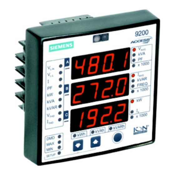
- Page 10 9200 Features Guide System Measurements System measurements x1000 Press the Up/Down x1000 buttons to display a FREQ FRE Q previous parameter x1000 x1000 value or the next in this group of System x1000 VARh measurements x1000 Each line of the display shows a System measurement. In the above example, line 1 = System Average Kilovolts (kV ) with a value of 450.1 kV;...
- Page 11 Display Mode Energy Readings Press the Up/Down buttons to x1000 display a previous parameter FREQ value or the next in this group of x1000 Energy readings Energy readings x1000 VARh MVAh MVARh An Energy reading wraps around the three lines of the front panel display.
-
Page 12: Configuration Mode
You must set the PTS (PT Scaling) register to “x1000” for the correct operation of a meter with the Megawatt option. Refer to the section “Before You Use the Megawatt Option” on page 6. To learn about Configuration mode, refer to the 9200 Installation and Basic Setup Instructions. Configurable Meter Settings... -
Page 13: Appendix A: Communications
Megawatt option in a Modbus network. It is assumed that the user is familiar with serial communications in general, and the Modbus protocol. Refer to the document 9200 Modbus Protocol for more information. Modbus Address Table In the following Modbus map, many numeric measurements are scaled. - Page 14 9200 Features Guide Modbus Addr Meter Measurement Format Scale Default Scale Description 40102 kVln c UINT16 40103 kVln avg UINT16 40104 kVll ab UINT16 40105 kVll bc UINT16 40106 kVll ca UINT16 40107 kVll avg UINT16 40108 UINT16 See note 7.
- Page 15 Modbus Address Table Modbus Addr Meter Measurement Format Scale Default Scale Description 40138 MWh del UINT32 40140 MWh rec UINT32 See note 40142 MVARh del UINT32 40144 MVARh rec UINT32 40146 MVAh del+rec UINT32 40148 V1 THD UINT16 40149 V2 THD UINT16 40150 V3 THD...
-
Page 16: Read-Write Configuration Map
9200 Features Guide Modbus Addr Meter Measurement Format Scale Default Scale Description Expansion, SnapOn 40700 UINT16 2, 25 regs M Wh del 41138 UINT32 M Wh rec 41140 UINT32 41142 M VARh del UINT32 41144 M VARh rec UINT32 41146... - Page 17 Read-Write Configuration Map Modbus Meter Configuration Format Scale Default Description Addr 44002 PT Primary UINT16 44003 PT Secondary UINT16 1 – 65535 44004 CT Primary UINT16 44005 CT Secondary UINT16 44006 V1 Polarity 44007 V2 Polarity 44008 V3 Polarity 0 = nor (Normal) Enumerated Normal 1 = inv (Inverted)
-
Page 18: Read-Write Control Map
2. Identifies the Original Equipment Manufacturer (OEM). 3. Options codes identify meter options. To see a table that cross-references Options Cards and options codes, refer to the 9200 Options Card Retrofit Instructions. 4. Number of seconds that the meter has been powered up. -
Page 19: Modbus Data Formats
13. The PML protocol is an ION compatible protocol used when other ION devices are sharing a RS-485 network. 14. The RTS Delay parameter defines the delay between the 9200 becoming ready to transmit data on the serial port, and the 9200 transmitting the data. -
Page 20: Appendix B: Configuration Reference Tables
9200 Features Guide Appendix B: Configuration Reference Tables Standard Measurements and Enhanced Packages 1 & 2 Standard Enhanced Pkg. 1 Enhanced Pkg. 2 Parameter Display Comm Pulse Display Comm Pulse Display Comm Pulse Volts L-N Avg Volts L-N Per Phase... -
Page 21: Meter Settings
Meter Settings Meter Settings These settings can be configured with the meter front panel or software. String Description Range (Values) Default 4W (4-Wire WYE) dELt (Delta) 2W (Single Phase) Delta tYPE Volts Mode Direct dEM (Demonstration) 3W (3-Wire WYE) dELd (Delta Direct) PT1 (Primary) 1 to (65.53 x 1000 LED) P P S S... -
Page 22: Digital Outputs
MWh Rec. and MVARh Rec. are represented by a lit “minus” (negative value) LED. †† In Ext 1 or Ext 2 mode, the digital outputs are reserved for Feature Packs or digital control. For digital output control information, refer to the 9200 Installation and Basic Setup Instructions. - Page 23 Meter Settings ††† Time Constant, sometimes called kT, is the number of units (MWh, MVAh, MVARh) per output transition. The digital output uses KY pulsing. This means that the relay changes from open to closed or from closed to open whenever kT units have been measured (20 transitions/second maximum).
- Page 24 For More Information Visit 3333 Old Milton Parkway sales/salesoffices.html Alpharetta, GA 30005 www.sea.siemens.com/access © Siemens Energy & Automation, Inc. Windows is a trademark and Order No. PMIM-9206A-0103 PDF 0800 Printed in the U.S.A. Microsoft is a registered trademark Siemens is a registered trademark of of Microsoft Corporation.