Table of Contents
Advertisement
Quick Links
Advertisement
Table of Contents
Troubleshooting

Related Manuals for Siemens 9810 Series


Summary of Contents for Siemens 9810 Series
- Page 1 9810 series User manual 7EN05-0390-00 09/2018 www.usa.siemens.com/pds...
- Page 2 Please note Electrical equipment should be installed, operated, serviced and maintained only by qualified personnel. No responsibility is assumed by Siemens Industry for any consequences arising out of the use of this material. A qualified person is one who has skills and knowledge related to the construction, installation, and operation of electrical equipment and has received safety training to recognize and avoid the hazards involved.
- Page 3 This digital apparatus complies with CAN ICES-3 (B) /NMB-3(B). About this manual This manual discusses features of the 9810 series power meter and provides configuration instructions. Throughout the manual, the term “meter” refers to all models of the 9810. All differences between the models, such as a feature specific to one model, are indicated with the appropriate model number or description.
-
Page 5: Table Of Contents
Table of Contents Safety precautions ...................13 Meter overview ..................14 9810 series .....................14 Your meter in an energy management system..........14 Communications..................15 Supported protocols ................15 Meter configuration ..................16 ION Setup device configuration tool.............16 Data display ....................16 Built-in webpages and web server feature..........16 Localization ..................16... - Page 6 Modbus best practices for serial ............45 Your meter as a Modbus master............46 Your meter as a Modbus slave ............47 Supported Modbus features..............50 Modbus implementation ..............51 Modbus map ..................52 Ethernet gateway ..................54 EtherGate ..................54 Modbus Ethernet gateway ..............56 Creating an Ethernet gateway site using ION Setup......57 HTTP......................58 Changing HTTP protocol using ION Setup ...........58 Secure website indicator..............59...
- Page 7 Digital inputs ...................76 Digital input applications ..............76 IRIG-B time synchronization ...............77 WAGES monitoring ................79 WAGES example ................79 Input metering ...................80 Digital outputs ..................82 Digital output applications ..............82 Energy pulsing ..................84 Default energy pulsing LED sources ............84 Configuring LED energy pulsing using ION Setup.........85 Webpages ....................88 Webpage interface ..................88...
- Page 8 Advanced security password setup ............117 Advanced security username and password through the display ....118 Changing your meter password using the display........118 Configuring standard security using ION Setup ........118 Configuring users and passwords using ION Setup (advanced security only) .....................
- Page 9 Standard waveform capture .............. 153 Delayed waveform capture ............... 154 Extended waveform capture ............. 155 Logging ....................157 Logging overview .................. 157 Default data logging configuration ............157 Configuring data logging using ION Setup ..........163 Waveform recording overview..............163 Default waveform recording configuration ..........
- Page 10 Maintenance ................... 192 Maintenance overview ................192 Firmware and templates................. 192 Firmware and templates overview ............. 192 Typical workflows................192 Laptop computer upgrade considerations .......... 193 Firmware upgrade considerations ............. 193 Editing accumulated energy values using ION Setup ......194 Loading meter firmware using ION Setup...........
- Page 11 Ethernet communications ..............215 RS-485 communications ..............215 Real-time clock ................215 Display.................... 215 Option modules ................216 Other ....................217 7EN05-0390-00...
-
Page 13: Safety Precautions
Safety precautions Safety precautions Installation, wiring, testing and service must be performed in accordance with all local and national electrical codes. DANGER HAZARD OF ELECTRIC SHOCK, EXPLOSION, OR ARC FLASH Failure to follow these instructions will result in death or serious injury. •... -
Page 14: Meter Overview
Support for meter event logging to a remote server (syslog) Your meter in an energy management system As a key piece in your energy and power management system, 9810 series meter provides highly accurate measurements and calculations to enable a variety of energy and power management applications. -
Page 15: Communications
Meter overview Inputs/outputs Alarming and alerting Highly accurate metering Data and event logging Powerful customization Measure Trending and forecasting Simple configuration Power quality monitoring Understand Easy access to information Time of use Cost allocation/tenant billing Energy efficiency Configurable Asset and network security management Perform basic setup using ION Setup, meter webpages... -
Page 16: Meter Configuration
• Use the charting function to view your meter’s recorded waveforms. You can download ION Setup from www.usa.siemens.com/pds. See the online ION Setup help, available from www.usa.siemens.com/pds, for instructions on connecting to your meter. Data display Built-in webpages and web server feature Your meter’s onboard internal web server and built-in web pages provide quick... -
Page 17: Email Messaging Feature
Specify the type of event that triggers an email alert, such as a power quality disturbance or interval for logged data. Email messages from your meter are received like any other email message. Meter models and accessories Commercial references for the 9810 series meter and accessories. Commercial reference Description US2:9810TC... -
Page 18: Installation And Commissioning
• See your device installation sheets for information related to installation. • See your product catalog pages at Siemens Industry for information about your device, its options and accessories. • Download updated documentation from www.usa.siemens.com/pds. For the latest information about your product, or for assistance in advanced features and custom functionality, contact your local Siemens Industry representative. -
Page 19: Functional Ground
Installation and commissioning 3 CT wiring For a 3-phase 3-wire system, the meter calculates residual current For a 3-phase 3-wire system, the meter measures the residual for Ground. current for Ground at I4. For a 3-phase 4-wire system, the meter calculates residual current For a 3-phase 4-wire system, the meter measures the residual for Neutral. - Page 20 Installation and commissioning NOTE: Refer to the display installation sheet QGH82365 for installation instructions. 1. Holding the display, turn the tightening wheel with a flat-head screwdriver until it disengages from the display. 2. Carefully pull the display away, just far enough to access the cable connector on the display.
-
Page 21: Removing The Meter From Back-To-Back Mounting Adapter
Installation and commissioning 3. Disconnect the display cable. Removing the meter from back-to-back mounting adapter You can uninstall the meter from the optional back-to-back mounting adapter. NOTE: Refer to the meter installation sheet QGH82363 for installation instructions. 1. Use a flat-head screwdriver to unlock the meter retainer clips. 7EN05-0390-00... -
Page 22: Option Modules
Installation and commissioning 2. Holding the meter firmly, swing it outwards and pull slightly upwards to detach it from the top retaining hooks. Option modules Option modules are ordered separately from your meter, and can be connected to your meter without specialized equipment. Option modules are identified based on how they physically connect to the meter’s external I/O bus. -
Page 23: Maximum Number Of Option Modules
Installation and commissioning The option modules are monitored and controlled by the meter’s ION modules. External I/O modules are mapped to the corresponding ION modules: Option module characteristic ION module characteristic Physical position: Module A to Module D ION module label: Port A to Port D Analog inputs A1 to A(n) Analog Input module A1 to A(n) Analog outputs Q1 to Q(n) -
Page 24: Configure Basic Metering Parameters
Installation and commissioning Before exiting the Setup Assistant, ION Setup performs a meter configuration test and displays the results. You can review the results and make changes as needed. To turn off the meter configuration test: 1. Click Tools > Options. 2. -
Page 25: Using The Phasor Viewer
Installation and commissioning 3. Configure the parameters in Metering Setup > Advanced if appropriate. Advanced tab Parameter Values Description PhaseOrder ABC, ACB Power system’s rotation order of voltage phases V4 PT Prim 1 to 999,999 V4 potential transformer's primary winding voltage rating V4 PT Sec 1 to 999,999 V4 potential transformer's secondary... -
Page 26: Communications
Communications Communications Communications overview Communications is the transfer of data to and from the meter and is controlled by a combination of hardware and software components in the meter. For each connected communications port, the meter uses the applicable communications protocol to establish communications with other devices or software. -
Page 27: Protocols, Ports And Connections
Communications Ethernet loop topology A. Ethernet switch or hub B. Ethernet connected meters C. LAN / WAN Protocols, ports and connections The Ethernet protocols supported by your device allow simultaneous connections through the IP service ports. NOTE: Some protocol port numbers are read-only and not configurable. Protocol Port (default) Number of... -
Page 28: Self-Discovery Over Ethernet
Communications Related Topics • Network protocol control Self-discovery over Ethernet Your meter supports DPWS (devices profile for web services) which allows for self-discovery of the meter when it is connected to your local area network. When you connect your meter to your network, your meter automatically appears in your network in Windows Explorer under Other Devices. -
Page 29: Ethernet Configuration
Communications Ethernet configuration In order to use Ethernet communications, you must configure your device’s IP settings. You need to enter network information for any Ethernet servers used by the device (for example, a DNS or email server). Contact your network system administrator for your IP address and other Ethernet network configuration values. - Page 30 Communications is enclosed in square brackets then append the port number. For example, to specify the default port for ftp (port 21), the format of the address is as follows: • IPv4: 169.254.0.10:21 • IPv6: [FE80::260:78FF:FE04:5943]:21 Configurable Ethernet settings ‘W’ indicates the setting can be configured (written) while ‘R’ indicates it is read- only.
- Page 31 Communications 1. Start ION Setup. 2. Open the Setup Assistant for your device. 3. Select Communications > Basic Ethernet and click the IPv4 or IPv6 tab. 4. Select the IP address then click Edit. 5. Select your IP address assignment mode. IPv4 Selection Mode...
- Page 32 Communications Stored IPv4 settings available using ION Setup Parameter Value Description IP address Contact your local network The IP address of your device. administrator for parameter values. Subnet Mask Contact your local network The subnet IP address of your administrator for parameter network.
- Page 33 Communications 4. Select a setting and then click Edit. NOTE: Contact your network system administrator for the appropriate values. General Ethernet settings available using ION Setup Parameter Value Description Ethernet device name configurable This name is associated with your meter when using DPWS.
- Page 34 Communications 3. Enter the appropriate value for the settings. 4. Click Advanced Settings to configure additional Advanced Ethernet settings, such as timeouts and enabling/disabling certain protocols over Ethernet, if needed. 5. Click Apply. NOTE: If you are changing the address you used to access the webpages, you will need to reconnect to the webpages after you click Apply.
- Page 35 Communications IPv6 settings available using the webpages Parameter Value Description IPv6 Assignment Mode Stored: The meter uses the IP Stored addresses that you manually DHCPv6 enter for IPv6 (Global address, gateway address). DHCPv6: The meter acquires its IP addresses from your network’s DHCP server.
-
Page 36: Dhcp
Communications 5. Configure your meter’s stored IPv4 Addresses, as required. Stored IPv4 address settings available using the display Parameter Values Description IP Address Contact your local Sets the IP address for the meter network administrator for Your meter’s default IP address is parameter values. -
Page 37: Meter Domain Name
Communications Meter domain name You can configure the meter as a DNS client in systems using a DNS server. Domain name resolution (DNS) A DNS (domain name system) server maps domain names to IP addresses. If you configure the meter to use a DNS server, the meter can communicate with other network resources using their domain names, rather than their IP addresses, and vice versa. - Page 38 Communications 3. Select a protocol from the list and click Edit. 4. Select the Enabled checkbox to enable the port. Clear the checkbox to disable the port. NOTE: The IEC61850 port is enabled when a valid CID file is uploaded to the meter.
-
Page 39: Serial Communications
Communications NOTICE LOSS OF ACCESS Failure to follow these instructions can result in loss of access to the device. Ensure you maintain sufficient access to communicate with and configure your device. NOTE: You cannot change the Ethernet port number assignments through your meter’s display. -
Page 40: Rs-485 Configuration
Communications RS-485 terminals Common. This provides the voltage reference (zero volts) for the data plus and data minus signals Shield. Connect the bare wire to this terminal to help suppress signal noise that may be present. Ground the shield wiring at one end only (either at the master or the last slave device, but not both. - Page 41 Communications Before configuring serial parameters, make sure you have a unique unit ID for your meter and know the serial network settings (protocol, baud rate, parity and stop bits). 1. Start ION Setup. 2. Open the Setup Assistant for your device. 3.
- Page 42 Communications 4. Click Advanced Settings to configure additional settings, if needed (for example, RS485 biasing or Rx Timeout). Basic serial communications settings available using the webpages Parameter Values Description Protocol ION, Modbus RTU, Modbus Sets the communications protocol for Master, DNP v3.00, your meter’s RS-485 port EtherGate, GPS: Truetime/ NOTE: the...
-
Page 43: Disabling Serial Communications Ports
Communications 4. Configure your meter’s serial settings as required. Serial communications settings Parameter Values Description Protocol ION, Modbus RTU, Sets the communications protocol for your Modbus Master, DNP meter’s RS-485 port v3.00, EtherGate, GPS: NOTE: the NONE setting stops Truetime/Datum, GPS: communications using this port. -
Page 44: Ion
See the ION Reference, available from www.usa.siemens.com/pds for further information about ION architecture and a detailed description of the different ION modules. See the ION Device Template Reference, available from www.usa.siemens.com/pds, for details on the modules and their configuration in your meter’s default template. Modbus Modbus is a master/slave communications protocol where the master initiates transactions and the slave(s) responds with the requested information or action. -
Page 45: Modbus Best Practices For Ethernet
The Ethernet Modbus protocol format. Modbus unit ID The identifier for a slave Modbus device. You can download your device’s Modbus map from www.usa.siemens.com/pds and get additional information about the Modbus protocol from www.modbus.org. Modbus best practices for Ethernet In order for your meter to operate as an Ethernet Modbus device, you must complete some prerequisite configuration. -
Page 46: Your Meter As A Modbus Master
Communications Your meter as a Modbus master Your meter as a Modbus master with Ethernet Modbus slave devices Your meter can function as a Modbus master with Ethernet Modbus slave devices. A. Ethernet B. Your meter C. Modbus slaves For Modbus mastering, you must add the Modbus slave devices using ION Setup. Your meter as a Modbus master with serial Modbus slave devices Your meter can function as a Modbus master with serial Modbus slave devices. -
Page 47: Your Meter As A Modbus Slave
Communications Make sure your master and slave devices have the prerequisite communications wiring and configuration before configuring your meter as a Modbus master. If the meter is a Modbus master over TCP/IP, the Modbus TCP/IP and Modbus RTU protocols must be enabled. NOTE: Devices supporting multiple simultaneous Modbus TCP connections can have communications delays. - Page 48 ON if the meter is a Modubs master 5. Configure the meter’s other serial port parameters as required. For Modbus mastering, you must add the Modbus slave devices using ION Setup. See your device’s Modbus map, available from www.usa.siemens.com/pds for Modbus register information. 7EN05-0390-00...
- Page 49 ON if the meter is a Modbus master 4. Configure the meter’s other serial port parameters as required. For Modbus mastering, you must add the Modbus slave devices using ION Setup. See your device’s Modbus map, available from www.usa.siemens.com/pds for Modbus register information. Related Topics •...
-
Page 50: Supported Modbus Features
Communications Related Topics • Configuring your meter as a Modbus master using ION Setup Supported Modbus features Your meter supports specific Modbus data classes, data formats, function codes and commands. Modbus data classes Class Description Coils Digital bits that can be read and written to Input status Digital bits that can be read Input registers... -
Page 51: Modbus Implementation
Communications Function Description Master/slave 43 (subcode 14) Read device identification Master and slave Read scattered holding registers Master and slave Modbus commands A Modbus master command to unit ID 0 is broadcast (sent to) all Modbus slave devices. The only supported broadcast command is preset multiple registers. For serial Modbus networks with only one slave device, the master can send commands using the single connection, one-to-one address of unit ID 248, regardless of the slave device’s actual unit ID. -
Page 52: Modbus Map
Modbus data to the meter. Modbus map Your meter’s default Modbus register information (map) is available for download from www.usa.siemens.com/pds. The Modbus register information includes: • registers and mapped values •... - Page 53 You can add extra Modbus information or duplicate information that is already in the fixed map to different Modbus registers using Modbus Slave modules. See the ION Reference available from www.usa.siemens.com/pds for detailed information about Data Mapping modules and Modbus Slave modules.
-
Page 54: Ethernet Gateway
Communications 8. In the Modbus Slave Map Setup screen you can click Delete to remove a Modbus register, Set Name to create a new name for the set of additional data mapped to Modbus, or Save As to save the additional data you have mapped to Modbus as a separate file. - Page 55 Communications • Confirm the serial network of devices are wired to the gateway meter’s serial communication port. • Confirm all serial devices are configured to have the same baud rate, serial port settings (for example, 8N1), and protocol (ION). • Confirm each serial device has a unique unit identifier (unit ID/address).
-
Page 56: Modbus Ethernet Gateway
Communications Related Topics • Creating an Ethernet gateway site using ION Setup Configuring EtherGate using the display Use the meter’s display to configure a serial port to use the EtherGate protocol. 1. Press the Home button. 2. Navigate to Setup Menu > Communications Setup. 3. -
Page 57: Creating An Ethernet Gateway Site Using Ion Setup
Communications NOTE: Modbus Ethernet gateway supports up to 32 Modbus TCP connections. Configuring a Modbus gateway using ION Setup You can configure Modbus gateway on your meter using ION Setup. Before you begin, make sure you have completed the following tasks: •... -
Page 58: Http
Communications 4. Select the General tab and configure the site. Parameter Values/Options Description Name Ethernet gateway site name Comm Link Ethernet Ethernet communications Ethernet options Gateway Ethernet gateway communications — Gateway Info: IP Addr IP address of the Ethernet gateway meter Gateway Info: Port 7801, 7802, 502 •... -
Page 59: Secure Website Indicator
Communications 2. Open the Setup Assistant for your meter. 3. Navigate to Communications > Advanced Ethernet and click the Protocols tab. 4. Select the Web protocol and click Edit. If prompted, enter the meter password. 5. Select the web protocol setting: Option Description Disabled... -
Page 60: Generating A New Self-Signed Ssl Certificate
Communications Generating a new self-signed SSL certificate You can generate a new self-signed certificate through the meter webpages. A self-signed certificate is valid during the lease period. Generating a new certificate renews the lease. 1. Use a browser to log in to your meter. 2. -
Page 61: Ftp File Structure And Permissions
Simple Network Management Protocol (SNMP) Your meter supports SNMP once you have enabled SNMP on your meter. You need to upload the meter’s MIB file (available from www.usa.siemens.com/pds) into the NMS managing your meter. Simple Network Management Protocol (SNMP) is part of the Transmission Control Protocol/Internet Protocol (TCP/IP) protocol suite. -
Page 62: The Meter In An Snmp System
SNMP trapping is only supported on SNMP v2. Configuring SNMP using ION Setup You can enable SNMP and configure SNMP trapping using ION Setup. You must download the ION MIB file from www.usa.siemens.com/pds 1. Start ION Setup. 2. Open the Setup Assistant for your meter. - Page 63 5. Review the rest of the SNMP information and modify if necessary. Configuring SNMP using your meter’s webpages You can configure SNMP trapping using your meter’s webpages. You must download the ION MIB file from www.usa.siemens.com/pds. 1. Connect to your meter’s webpages. 2. Go to Setup > SNMP Parameters.
-
Page 64: Snmp Implementation
Your meter is compliant with MIB-II as defined by the standard MIB file RFC 1213. SNMP requires that you load your meter’s ION MIB file (available for download from www.usa.siemens.com/pds) into the NMS. You must install RFC 1213, which is required to read basic network information for the meter (for example, TCP/IP traffic or number of packets received), if it is not included with your SNMP manager software. -
Page 65: Default Snmp Mapping
Communications See the ION Reference, available from www.usa.siemens.com/pds, for detailed information on the SNMP Mapping, SNMP Options and Alarm Options modules. Default SNMP mapping Enabling SNMP provides SNMP access to the meter values linked to the SNMP Mapping module. You can configure the SNMP Mapping module to link to different meter values. By... -
Page 66: Iec 61850
ACCESS read-only STATUS mandatory DESCRIPTION “Host Meter Voltage Line A to Neutral Units = V (Volts)” ::= { Siemens Industry 34 } You must update the variable name and description to match the meter values connected to the SNMP Mapping module:... - Page 67 The IEC 68150 configuration file stored in a location accessible by ION Setup. The configuration file is created by customizing the IEC 61850 device (ICD) file, which can be downloaded from www.usa.siemens.com/pds. • FTP access to your meter from the computer running ION Setup.
-
Page 68: Configuring Digital Outputs For Iec 61850 Control Using Ion Setup
14. Navigate to the IEC 61850 GGIO Onboard folder and select the SPCS.stVal output register that corresponds to the digital output. 15. Click OK and Send to save your changes to the meter. See the ION Reference, available from www.usa.siemens.com/pds, for information about the IEC 61850 GGIO and Digital output modules. 7EN05-0390-00... -
Page 69: Dnp
See the online ION Setup help for instructions on connecting to your meter and accessing the Setup Assistant, which can be used to modify your meter’s DNP port settings and default DNP map. Go to www.usa.siemens.com/pds to download your meter’s DNP 3.0 device profile document for detailed information on your meter’s default DNP map and implementation and the Multiport DNP 3.0 and ION... -
Page 70: Inputs / Outputs
Inputs / outputs Inputs / outputs I/O overview Your meter has onboard digital I/O which can be increased by adding optional digital and analog I/O modules to expand your meter’s I/O capabilities. WARNING UNINTENDED OPERATION Failure to follow these instructions can result in death, serious injury, or equipment damage. -
Page 71: Input/Output Ion Modules, Ports And Labels
Port D Q1 - Q2 NOTE: When configuring your meter, the configuration interface may show all of the possible ports, regardless of what is physically available on your meter. See the ION Reference, available from www.usa.siemens.com/pds for more information about ION modules. 7EN05-0390-00... -
Page 72: I/O Option Modules
Inputs / outputs Related Topics • Option modules I/O option modules I/O option modules provide increased digital and analog input/output (I/O) capabilities for your meter. These I/O modules can be used to monitor the status of breakers, control analog or digital transducers, or receive signals that can be interpreted to provide WAGES data for your energy system. -
Page 73: Analog Inputs
Inputs / outputs Related Topics • Configuring option module analog inputs using ION Setup • Configuring option module analog outputs using ION Setup • Configuring option module digital inputs using ION Setup • Configuring option module digital outputs using ION Setup Analog inputs Analog input applications You can use an analog input to monitor an analog signal, for example a flowmeter,... -
Page 74: Analog Input Zero Scale And Full Scale Values
If the sensor’s output range does not match your meter’s hardware limits, you must calculate the full scale and/or zero scale values by analyzing the system. See the ION Reference, available from www.usa.siemens.com/pds, for detailed information about the Analog Input module and full scale and zero scale calculations. -
Page 75: Analog Outputs
If your meter’s analog output range does not match the range of the connected analog sensor, you must calculate the full scale and zero scale values by analyzing the system. See the ION Reference, available from www.usa.siemens.com/pds for detailed information about the Analog Output module and full scale and zero scale calculations. -
Page 76: Digital Inputs
Inputs / outputs Analog outputs are available on the optional I/O modules you can connect to the base of your meter. Calculate your zero scale and full scale values based on the measured value and the analog output range of your meter. Make sure that the analog output port that you want to use is properly connected to an analog receiver. -
Page 77: Irig-B Time Synchronization
Inputs / outputs Digital input signal State output Trigger output (Input Mode = PULSE) KYZ mode If you set Input Mode to KYZ, a pulse is generated at the Trigger output for each change of state transition, i.e. from OFF-to-ON and from ON-to-OFF transitions. Digital input signal State output Trigger output... - Page 78 Inputs / outputs Related Topics • Configuring time information using ION Setup Configuring onboard digital inputs using ION Setup You can use ION Setup to configure your meter’s digital inputs. 1. Start ION Setup. 2. Open the Setup Assistant for your meter. 3.
-
Page 79: Wages Monitoring
Inputs / outputs 6. Once the parameter has been configured, click OK to save the setting to the meter. Parameter Value/Range Description Input Mode Pulse, KYZ, Specifies how the meter processes the signal: A/C, IRIG-B • Pulse: the meter counts an entire pulse (from off- on to on-off) as one input. -
Page 80: Input Metering
Inputs / outputs A. Water flow meter (15 kL/pulse) B. Energy meter with digital input 1 assigned to input metering channel 1 and configured with unit kL (kiloliters) C. Energy management system with WAGES analysis capabilities Input metering Your meter’s digital inputs can be used to count pulses from transducers and convert the pulses to energy measurements. - Page 81 Inputs / outputs 4. Select the input metering channel you want to configure and click Edit. The Input Metering Channel Setup screen is displayed. 5. Select Enabled to enable the input metering feature. 6. Click Select to define which digital input is the pulse source for the input metering channel.
-
Page 82: Digital Outputs
Inputs / outputs 10. Configure your meter to log the input metering data if required. Parameter Description Pulse Weight Enter the value per pulse. Units Select the measurement units associated with the pulse. NOTE: Include source identification information by entering “@” followed by the source identifier. - Page 83 Inputs / outputs 4. Configure the digital output by selecting the parameter and clicking Edit. Enter the meter password if prompted. Parameter Value/range Description Source Digital/Boolean Link this input to the value that drives the state of the digital output. If Source is not linked, the digital output state is driven by the Force ON, Force OFF values.
-
Page 84: Energy Pulsing
Inputs / outputs 5. Configure the digital output by selecting the parameter and clicking Edit. Parameter Value/Range Description Source Digital/Boolean Link this input to the value that drives the state of the digital output. If Source is not linked, the digital output state is driven by the Force ON, Force OFF values. -
Page 85: Configuring Led Energy Pulsing Using Ion Setup
Inputs / outputs See the ION Reference, available from www.usa.siemens.com/pds, for more information. Related Topics • Alarm and status LED indicators Configuring LED energy pulsing using ION Setup You can configure your meter’s energy pulsing LEDs for energy pulsing using ION Setup. - Page 86 ION and the power system your meter is connected to. See the ION Reference, available from www.usa.siemens.com/pds, for more information. Calculate your maximum kWh/pulse (pulse weight) value To calculate the kWh/pulse (pulse weight) value, divide the highest kW value you can expect by the required pulse rate.
- Page 87 (0.444 kWh/sec)/(2 pulses per second) = 0.222 kWh/pulse 3. If using KYZ Output Mode, adjust for the KY giving one pulse per 2 transitions if necessary. (0.222 kWh/pulse)/(2) = 0.111 kWh/pulse See the ION Reference, available from www.usa.siemens.com/pds for detailed information about the Calibration Pulser module. 7EN05-0390-00...
-
Page 88: Webpages
Webpages Webpages Webpage interface Your meter comes with default webpages that contain typical elements. 9810 Siemens 9810 Meter_04fb25 Meter type and model, device name Username Main menu Webpage menu Webpage content NOTE: This graphic is representative only, and your meter’s webpages may appear differently than shown. -
Page 89: Accessing Webpages For Data Viewing And Meter Configuration
Webpages Webpage menu Webpage content Inputs/Outputs • Digital inputs • Digital outputs • Analog inputs • Analog outputs Waveforms View waveforms from your meter, using the meter’s COMTRADE files Control Webpage menu Webpage content Resets Perform resets, and view when previous resets were performed. Diagnostics Webpage menu Webpage content... -
Page 90: Viewing Files Using Your Meter's Webpages
Webpages On a hardware-locked meter, you cannot add, delete or modify any webpage files. If you are connected to your device over Ethernet, changing Ethernet configuration parameters without another method of configuration enabled may cause loss of communications with your device and render it inaccessible. NOTICE LOSS OF ACCESS Failure to follow these instructions can result in loss of access to the... -
Page 91: Creating Custom Webpages For Your Meter
You can create custom webpages to view data or access configuration parameters from your meter. Download the your meter’s Modbus registers map from www.usa.siemens.com/pds. 1. Connect to your meter’s internal FTP site. 2. Go to web > examples. Select samplereadings.html to create a data value webpage, or select sampleconfiguration.html to create a configuration... - Page 92 The sample webpages are stored in the documents folder on your meter’s internal FTP site. Your meter’s Modbus register map is available from www.usa.siemens.com/pds. If required, your meter’s ION handles document is packaged with the meter firmware file which is available for download from www.usa.siemens.com/pds.
- Page 93 Webpages Line # Sample HTML <tr class="minor"> <td>$%localizedString(I a)#$ <span unitsreg="I a"></span></td> <td regname="I a mn"></td> <td regname="I a"></td> <td regname="I a mx"></td> </tr> <tr class="minor"> <td>$%localizedString(I b)#$ <span unitsreg="I b"></span></td> <td regname="I b mn"></td> <td regname="I b"></td> <td regname="I b mx"></td> </tr>...
- Page 94 Webpages Sample webpage data viewing content description Line # Description SampleMonitorPane.html The HTML filename, including the HTML extension (.html). This filename must comply with FTP filename conventions (no spaces or special characters). The filename (without the HTML extension) is the name shown on the webpage menu. <h3 target="sample-readings">...
- Page 95 Sample webpages are stored in the documents folder on your meter’s internal FTP site. Your meter’s Modbus register map is available from Siemens Industry. If required, your meter’s ION handles document is packaged with the meter firmware file which is available for download from www.usa.siemens.com/pds.
- Page 96 Webpages Line # Sample HTML <div class="content-fit"> <form id="formSampleSettings"> <div class="accordion"> <h3 target="sample-basic">$%localizedString(Basic Settings)#$</h3> <div id="sample-basic"> <table class="formtable"> <tr> <th> </th> <th> </th> </tr> <tr> <td>$%localizedString(Ethernet)#$</td> <td> </td> </tr> <tr class="minor"> <td>$%localizedString(MAC Address)#$</td> <td regname="MAC Address"></td> </tr> <tr class="minor"> <td>$%localizedString(Ethernet Device Name)#$</td> <td><input name="Ethernet Device Name" type="text" /></td> </tr>...
- Page 97 Webpages Line # Sample HTML <td><select name="Enable Web Server"></select> </td> </tr> </table> </div> </div> <input type="submit" class="apply" value='$%localizedString(Apply)#$' /> </form> <script type="text/javascript"> SetupPane.init('formSampleSettings'); formChangeDetection.initFormChangeDetection('#formSampleSettings', '#dialogFormChanges'); </script> </div> Sample setup webpage content description Line # Description SampleSetupPane.html The HTML filename, including the HTML extension (.html). This filename must comply with FTP filename conventions (no spaces or special characters).
- Page 98 Webpages Line # Description <td>$%localizedString(IP Address)#$</td> IP Address is the row heading. This heading is translated if possible. <td><input name="IP Address" type="text" /></td> This displays the instantaneous value of the configurable named register IP Address in a text-edit field. The type must match the named register type, in this case, an alphanumeric string. <h3 target="sample-advanced">...
-
Page 99: Display
Display Display Display overview The display allows you to view meter data and perform basic configuration. NOTE: The display backlight dims after a defined period of inactivity. When the meter detects an unacknowledged active high priority alarm, the display flashes until the alarm is acknowledged. Display Display port Optional 24 V DC AUX power input... -
Page 100: Display Icons
Display Alarm icon The alarm icon indicates the highest level and state of alarms detected by your meter. For example, if the meter detects a low priority and a high priority active alarm, the alarm icon indicates a high priority active alarm. NOTE: Alarms can only be viewed and acknowledged through your display. -
Page 101: More Screens Access
Display Description Icon Tap More to access additional screens. Tap Left arrow to select item to the left or to return to the previous screen. Tap Right arrow to select item to the right. Tap Up to navigate menu items or screens. Tap Down to navigate menu items or screens. -
Page 102: Auto-Scaling Feature
Display • Display mode indicator is set to normal (NORM) mode. • Revenue lock icon indicates a locked state (green and closed). • Alarm icon indicates an unacknowledged high priority historic alarm (red outline bell). • All parameter labels and associated parameter data are cleared. Display screen title bar and display icons are retained. -
Page 103: Norm Mode Display Menu
Display Norm mode display menu The Norm mode display screens show measured and calculated information about the power system being monitored. NOTE: Your meter’s menus may appear slightly different than shown depending on your display settings. Alt mode display menu The alt mode display menu allows you to view data screens and access the setup menu. - Page 104 Display Summary Summary Alarms Active Alarms Active Alarms Acknowledge All Alarm Details Historical Alarms Historical Alarms Acknowledge All Alarm Details Basic Readings Voltage Volts L-L Volts ll Average Volts ll Min Volts ll Max Volts L-N Volts ln Average Volts ln Min Volts ln Max Volts Unbalanced Current...
-
Page 105: Setup Menu
Display Menu Menu screens Content Power Power summary, • Per-phase and total kW, kVAR and kVA values, demand, power factor along with minimum and maximum values. • Delivered and received demand values including peak demand. • Per-phase and total power factor along with minimum and maximum values. -
Page 106: Meter Setup Using Your Display
Display Setup Menu Meter Setup Volts Mode Volts Mode PhaseOrder PT/CT Setup PT Primary PT Secondary CT Primary CT Secondary I4 Primary I4 Secondary Voltage Polarity Setup Va Polarity Vb Polarity Vc Polarity Current Polarity Setup Ia Polarity Ib Polarity Ic Polarity I4 Polarity Nominal... - Page 107 Display 2. Press to highlight the different setup menu selections. Highlight Meter Setup and press to select the meter setup screens. The Volts Mode setup screen is displayed. to highlight Volts Mode. Press to edit the volts mode. The 3. Press Enter Password screen is displayed.
- Page 108 Display 7. In the Volts Mode screen, press to go to the PT/CT Setup screen. 8. In the PT/CT Setup screen, press to highlight the potential transformer (PT) or current transformer (CT) value for editing. Press edit the highlighted value. NOTE: If you have exceeded the password timeout period, you are prompted to enter your meter’s display password.
-
Page 109: Creating Custom Displays Using Ion Setup
Display Numeric format setup Parameter Values Description Digit Grouping 1000.0, 1,000.0, 1 000,0 Specifies how digits are grouped for display Volts Resolution 1., 1.X, 1.XX, 1.XXX, 1. Specifies the number of decimal places XXXX displayed for voltages Current 1., 1.X, 1.XX,1.XXX, 1. Specifies the number of decimal places Resolution XXXX... -
Page 110: Display Scaling
7. When you have finished configuring the display units, click Send to send your changes to the meter and close the Display Options screen. See the ION Reference, available from www.usa.siemens.com/pds, for more information about the Display Options module and your meter’s ION architecture. - Page 111 Display Icon Description Your remote display needs updated firmware for compatibility with your meter. Your remote display is downloading a firmware upgrade. Do not disconnect your remote display from your meter. Your remote display is undergoing a firmware upgrade. Do not disconnect your remote display from your meter.
-
Page 112: Security
Security Security Security overview Your Siemens Industry product is equipped with security-enabling features. These features arrive in a default state and can be configured for your installation needs. Please note that disabling or modifying settings within the scope of these individual features can impact the overall security robustness of the device and ultimately the security posture of your network in either positive or negative ways. -
Page 113: Revenue And Billing Security Features
Security Related Topics • Network protocol control using ION Setup • Network protocol control using the meter webpages • Network protocol control using the meter display • Protocols, ports and connections Revenue and billing security features Selected meter models support additional hardware and firmware locking to prevent unauthorized access to revenue-related parameters and settings. -
Page 114: Nerc Cip
Security NERC CIP North American Electric Reliability Corporation (NERC) Critical Infrastructure Protection (CIP) is a set of standards and requirements designed to help protect the North American power generation and transmission system and covers aspects such as critical cyber asset identification, electronic security perimeters, and systems security management. -
Page 115: Standard And Advanced Security Features
Security Standard and advanced security features Security settings allow you to configure security features on your meter. Parameter Standard/ Details advanced Meter password Standard/ The meter’s password is used to confirm user access advanced when configuring the meter through the display or over communications. -
Page 116: Communications Protocol Lockout Overview
Security Communications protocol lockout overview The communications protocol lockout security feature allows you to set the number of invalid login attempts that each user can make using a particular protocol and communications method before being locked out (a user is defined as a user login and password combination). -
Page 117: Standard Security Password Setup
Security Related Topics • Configuring standard security using ION Setup Standard security password setup It is strongly recommended that you change your meter’s password from the default value of 0 (zero). Your meter’s username and password cannot be retrieved if lost. If you lose your meter’s user access information, you will not be able to change any settings or access any data that requires this login information. -
Page 118: Advanced Security Username And Password Through The Display
Security Example Facility manager Plant engineer Worker1 Worker2 Guest User name USER1 USER2 USER3 USER4 USER5 Password FacM1! PE321! Emp1! Emp2! 123456789 Full meter setup Security setup Test mode Communications setup Peak demand reset Time sync Read access Advanced security username and password through the display You can enter your username and password on the meter’s display when advanced security is enabled. - Page 119 Security 4. Select the appropriate security configuration file (*.scf) to configure your meter: – Standard: allows you to configure basic security and communications protocol lockout. – Advanced: includes the standard security features and adds user access/ password security settings. 5. The standard options or advanced options configuration screen appears. Configure the security parameters as required, some parameters can only be configured using advanced security.
-
Page 120: Configuring Users And Passwords Using Ion Setup (Advanced Security Only)
Security 10. If you have selected standard security, click Finish. You are prompted to save your security configuration to a file which can be loaded onto other meters. NOTE: If you chose to save your security file, enter a descriptive name and click Save. -
Page 121: Loading A Security Configuration File Using Ion Setup
Security 2. Select the appropriate values to configure the user’s access. Some access levels require that multiple access options be selected. For example, if you enable Security Config Access, Full Meter Config Access is also enabled. 3. Select the user and click Password. The password entry screen appears. -
Page 122: Alarms And Alerts
• Historical: the alarm condition previously existed but the condition has since returned to a non-alarm state. See the ION Reference, available from www.usa.siemens.com/pds, for more information about Setpoint, Relative Setpoint, Digital Input, Disturbance Analyzer, Transient and Sag/Swell modules. Related Topics •... - Page 123 Alarms and alerts High-speed alarm High-speed alarms have a detection rate of once every half-cycle. 3-phase alarms Alarms on 3-phase systems are evaluated per phase and reported for each phase. Some alarms, such as the sag/swell alarm, are evaluated per phase, but reported as a single alarm: Each of the three phases are evaluated for the setpoint condition individually, but there is only one alarm generated.
-
Page 124: Relative Setpoint
NOTE: To stop a digital alarm from being displayed, set the alarm priority to Info Only. Disabling the digital alarm (setting it to Force Off) will disable all alarming functions of the associated digital input. See the ION Reference, available from www.usa.siemens.com/pds, for more information about the Digital Input module. 7EN05-0390-00... -
Page 125: Transient Alarms
100. For example, if you want transients recorded when voltage deviates from nominal by 20%, enter 120 into the Threshold setup register. For more information on the Transient module, download the ION Reference at www.usa.siemens.com/pds. Related Topics • Transient overview Alarm event priorities Your meter’s alarm priorities correspond to event priority ranges. -
Page 126: Default Alarms
Alarms and alerts For active high priority alarms, the meter’s display will also flash until the alarm is acknowledged. There is also an alarm LED to indicate the meter’s alarm condition. Alarm Alarm icon Alarm icon flash Alarm LED Meter display Active high Red solid bell Flash if not... -
Page 127: Alarm Information
Alarms and alerts Name Priority Description Default Transient/Waveshape High Transient alarm Disabled Digital In Info Only Digital input alarms Enabled Number of alarms determined by the total number of available digital inputs NOTE: Info Only alarms are not displayed. Alarm information You can view information about an alarm from your meter’s display. - Page 128 Alarms and alerts WARNING INACCURATE DATA RESULTS Failure to follow these instructions can result in death, serious injury, or equipment damage. • Do not use data displayed on the display or in software as a substitute for proper workplace practices or equipment maintenance. •...
- Page 129 Alarms and alerts Disabling and enabling alarms using the display You can disable alarms using the meter’s display when you are performing maintenance tasks on your system and want to prevent nuisance alarms. NOTE: To stop an alarm from being displayed without impacting other metering features, set the alarm priority to Info Only.
-
Page 130: Sag/Swell Overview
Alarms and alerts 7. Click Save to save the settings to your meter. Parameter Value/Range Description By Percentage By Percentage/By Value When available, specifies if the Pickup and Dropoff entries are by percentage or by value. If the option is not available, pickup and dropoff entries are by value. Force Off Checked/Unchecked Forcing the alarm off disables all functions of the associated input. -
Page 131: Configuring Transient Alarms Using Ion Setup
Alarms and alerts 5. Configure the parameters as required. The values you need to set vary depending on the type of sag/swell alarm you are configuring. Voltage sag/swell setup parameters Parameter Value/Range Description Enable/Disable Enabled or Disabled Specifies if sag/swell recording and alarming is enabled. Nominal 1 to 999,999 Specifies the nominal voltage value used for sag/swell detection. -
Page 132: Alerting
Alarms and alerts 5. Configure the parameters as required. Transient setup parameters Parameter Value/Range Description Enabled/Disabled Enabled or Disabled Specifies if transient recording and alarming is enabled. Nominal 1 to 999,999 Specifies the nominal voltage value used for transient detection. Threshold Percentage of nominal Specifies the threshold expressed as a percentage of the nominal voltage, plus... -
Page 133: Setpoint Learning Overview
SMTP settings and connecting it via Ethernet to an SMTP mail server in order to send an alert by email. Go to www.usa.siemens.com/pds to see the ION meter alerts technical note for detailed information on creating and configuring alerts, and the ION Reference for detailed information about the Alert module and its operation. -
Page 134: Implementing Standard Alarm Setpoint Learning Using Ion Setup
Learned sag limit = 87% Maximum duration remaining Stable learning time See the ION Reference, available from www.usa.siemens.com/pds, for more information on Sag/Swell, Setpoint and Relative Setpoint modules. Implementing standard alarm setpoint learning using ION Setup You can use ION Setup to implement setpoint learning, which analyzes your power system and recommends settings. - Page 135 Alarms and alerts 4. Select a setpoint and click Learn. The Global Setpoint Learning screen is displayed. 5. Select the setpoint tabs to view existing configured or learned setpoint information. 6. Click Setup. The Alarm Learning Setup screen is displayed. Setpoint learning parameters Parameter Value/Range...
-
Page 136: Implementing Transient Learning Using Ion Setup
Alarms and alerts 4. Select Voltage and click Learn. NOTE: Learning is not supported for Current Swell and Current Sag. NOTE: You can manually configure the limit values by selecting the parameter and clicking Edit. The Global Setpoint Learning screen is displayed. 5. - Page 137 Alarms and alerts 7. Click Start to begin transient learning. – Learning status and time remaining are indicated in the Learning Status box. – Click Abort to stop transient learning. 8. Apply the learned values. – Automatic: the threshold is automatically applied unless there are issues with the learning process.
-
Page 138: Power Quality
Power quality Power quality Power quality overview Your meter measures voltage and current harmonics, and calculates several harmonic distortion values, including K-factor and crest factor. Configure your meter with the power system’s nominal values for voltage, current and frequency in order for the meter to perform power quality calculations. Considerations for power quality configuration using ION Setup Use ION Setup to configure sag/swell, transient and advanced power quality logging. -
Page 139: Power Quality Logging
Power quality Related Topics • Configure basic metering parameters • Configuring sag/swell alarms using ION Setup • Logging overview Power quality logging Sag/swell overview Your meter monitors your power system’s voltage and current for sags and swells (INCITS (CBEMA) Type 2 and Type 3 disturbances). When sag/swell limits are defined and alarming is enabled, the meter reports the disturbance’s magnitude and duration, and logs data and waveform records associated with the disturbance. - Page 140 Power quality 7. The High Speed Recording screen displays the settings for the high-speed Sag/Swell data recorder (Sg/Sw HS Log — Data Recorder #6). You can configure these settings for the meter to perform burst data logging. Parameter Description Enable Burst Data Select or clear this check box to turn burst data logging on or off.
-
Page 141: Transient Overview
Power quality 10. Click Finish. You are returned to the Sag/Swell Logging screen and the entry shows your new configuration. If nothing happens when you click Finish, check the log depths and buffer depths for all your other data logs to make sure that the meter has enough memory for these changes. -
Page 142: Configuring Advanced Pq Using Ion Setup
Power quality 7. The Waveform Log Setup screen allows you to configure the waveform recorder for Standard or Delayed waveform capture. NOTE: The Transient Logging Wizard does not support Extended waveform capture. See “Waveform capture”, page 153 for details on Standard, Delayed and Extended waveform capture. - Page 143 Power quality 2. Open the Setup Assistant for your meter. 3. Navigate to Power Quality > Advanced PQ Logging. 4. Select 4-30 Enable and click Edit to configure your meter’s IEC 61000-4-30 logging parameters. 5. Configure the settings as required: IEC 61000-4-30 Setup Parameter Description...
- Page 144 Power quality 12. Configure the settings as required: IEEE 519 Configuration Parameter Description Nominal Voltage Displays the nominal voltage value used for IEEE 519. NOTE: If you change the Nominal Voltage, you must return to this setup screen and manually update the IEEE 519 configuration.
-
Page 145: Rapid Voltage Change Overview
You can configure the Sag/Swell module to detect and measure RVC and record the event in the meter’s Event Log. For more information on the Sag/Swell module, download the ION Reference at www.usa.siemens.com/pds. Related Topics • Sag/swell overview •... -
Page 146: Current Crest Factor
Power quality For a pure sinusoidal waveform, crest factor is equal to 1.414. The meter uses the following equation to calculate crest factor: C = Crest factor peak = Voltage peak peak = Voltage RMS Current crest factor Crest factor is the ratio of peak to RMS current values. For a pure sinusoidal waveform, crest factor is equal to 1.414. -
Page 147: Thd And Tdd
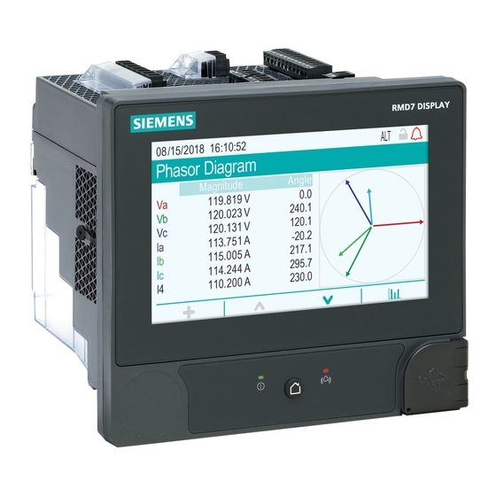
/ RMS *100% TDD = H / Demand *100% See the ION Reference, available from www.usa.siemens.com/pds, for details about the Harmonics Measurement module. Phasors Phasors are used to represent the voltage and current magnitude and angles. The length of the lines in the phasor diagram represent the relative magnitude of the voltages with respect to the other phase voltages, and the currents with respect to the other phase currents. -
Page 148: Disturbance Direction Detection Overview
Power quality IEC 60255-24 (COMTRADE) The meter can provide waveforms in COMmon format for TRAnsient Data Exchange (COMTRADE) format. COMTRADE records are generated from the existing Waveform Recorder modules that are connected to the COMTRADE module. See the COMTRADE and ION Technology technical note for details. IEEE 519 The IEEE 519 framework is composed of numerous ION modules including: Harmonics Evaluation, Harmonics Measurement, Counter and more. -
Page 149: Comtrade
ION Setup. NOTE: You can view your meter’s event log throughION Setup, the meter webpages or display. See the ION Reference, available from www.usa.siemens.com/pds, for more detailed information about the Disturbance Direction Detection module. Related Topics •... -
Page 150: Waveforms On Your Meter's Webpages
NOTE: COMTRADE files can only be downloaded using an Ethernet connection. They cannot be downloaded using serial, modem or Ethernet gateway connections. See the COMTRADE and ION technology technical note, available from www.usa.siemens.com/pds, for detailed information about COMTRADE file formats and implementation. Related Topics •... - Page 151 Power quality A. Select the COMTRADE module to view (COMTRADE_1 is set up by default; you can also set up COMTRADE_2 or COMTRADE_3) B. Select the particular COMTRADE waveform to view C. Show / hide parameters D. View details E. Zoom in / out Viewing waveforms on your meter’s webpages Use the waveform viewer on your meter’s webpages to view the meter’s COMTRADE waveform files.
-
Page 152: Burst Data Logging
Power quality 6. Use the bar at the bottom to zoom in / zoom out on a particular section of the waveform, or to scan through the waveform with the selected zoom level. – Draw a window over a particular area to zoom in on that section of the waveform. -
Page 153: Waveform Capture
Power quality 1 record triggered 10 Pre-trigger Records 5 Post-trigger Records Buffer Depth 6 x 16 = 96 Data Log register Depth (trigger record) 16 x 16 Input 1 value Input 2 value = 256 Input 3 value . . . Data log set is 10 + 1 + 5 = 16 Burst data log set = [pre-trigger records] + [post-trigger records] + [actual trigger record] = 10 + 5 + 1 = 16. -
Page 154: Delayed Waveform Capture
Power quality Waveform recording triggered Waveform record captured at trigger Delayed waveform capture The meter’s Waveform Recorder modules support delayed waveform capture. The Waveform Recorder module’s Record Delay Cycles setup register specifies how many cycles to delay the waveform capture after the Record input is triggered. -
Page 155: Extended Waveform Capture
Power quality Extended waveform capture The meter’s Waveform Recorder modules support extended waveform capture. The Waveform Recorder module’s Pre-trigger Records setup register specifies how many pre-event records are saved with each triggered recording. The Post- trigger Records setup register specifies how many post-event records are saved with each triggered recording. - Page 156 Power quality 1 record triggered 4 x 9 = 36 register (trigger record) 16 x 9 = 144 Waveform log set is 2 + 1 + 6 = 9 The waveform log set for the extended waveform capture = [pre-trigger records] + [actual trigger record] + [post-trigger records].
-
Page 157: Logging
You can also configure the meter to email data from the logging frameworks. Download the Internal email client feature technical note at www.usa.siemens.com/pds for instructions on how to configure your meter to email logged data. Meter events are recorded in the meter’s onboard event log. You can also configure the meter to record events to an external SysLog (systems log) server. - Page 158 Logging Parameter Description kWh del int Interval kWh delivered kWh rec int Interval kWh received kVARh del int Interval kVARh delivered kVARh rec int Interval kVARh received Historic data logs Three historic data logs are used to record standard power system quantities, such as phase current, phase voltage and power factor.
- Page 159 Logging Parameter Description MU Vln a^2h int Phase A interval voltage Line-to-Neutral squared hours MU Vln b^2h int Phase B interval voltage Line-to-Neutral squared hours MU Vln c^2h int Phase C interval voltage Line-to-Neutral squared hours Harmonics logs Two harmonics logs record various harmonics data, including K-factor and Total Harmonic Distortion (THD).
- Page 160 Logging • Interval = Triggered on demand By default, it logs the following values from the Factory module’s setup registers: Parameter Description FAC1 Vnominal Nominal voltage setting FAC1 NomFreqNum Expected frequency of operation Rapid voltage change log The RVC Log (Data Rec 23) provides details of rapid voltage changes related to sag/swells (power quality events).
- Page 161 The meter logs EN50160 counter data for present and previous observation periods as well as EN51060 events. Download the EN50160 2010 compliance and ION meters technical note at www.usa.siemens.com/pds for more information about your meter’s EN50160 compliance. IEC 61000-4-30 compliance logs The IEC 61000-4-30 compliance logs are used to log parameters related to the International Electrotechnical Commission’s IEC 61000-4-30 standards’...
- Page 162 Intrp (Data Rec 22) V Intrp DrtnAll (voltage interruption duration - all voltages) Download the IEC 61000-4-30 Compliance and ION Meters technical note at www.usa.siemens.com/pds for more information about your meter’s IEC 61000-4- 30 compliance. IEEE 519 compliance logs The IEEE 519 compliance logs are used to record IEEE 519 compliance...
-
Page 163: Configuring Data Logging Using Ion Setup
Logging Data recorder IEEE 519 component logged V3Hrm 17-32 (Data Rec 49) V3 voltage harmonics V3Hrm 33-48 (Data Rec 55) V3 voltage harmonics Related Topics • Configuring data logging using ION Setup Configuring data logging using ION Setup Use ION Setup to configure the meter’s data recorders. Changing the meter’s data recorder configuration clears existing data in that data recorder. -
Page 164: Default Waveform Recording Configuration
A power event where the voltage or current rises above the nominal value. Transient A power event where a short duration surge of electrical energy is detected. See the ION Reference, available from www.usa.siemens.com/pds, for more information on the Waveform Recorder module and its settings. Related Topics •... - Page 165 Logging These waveform logs and their configuration are used by other components of your power monitoring system. Do not change the default configuration of any of the logs unless you understand the impact of the change on these power monitoring system components, the data they use and your meter’s memory. Waveform Recorder modules The factory-default Waveform Recorder modules are preconfigured to capture sag/swell and transient power quality events.
-
Page 166: Event Log Overview
NOTE: This example is representative only, and your meter’s event log may appear different than shown. See the ION Reference, available from www.usa.siemens.com/pds, for more information about the Event Log Controller module and other ION modules. Default event log configuration Your meter logs all configuration changes, meter access events, and power system events. -
Page 167: Syslog Overview
Logging Related Topics • Alarms overview User triggered event log entries The Event Log includes an association between security-related events and the username that was logged in to the meter during the event. When a user produces an event, such as a reset, successful or unsuccessful login attempts, user lockout or setup change, it is written to the event log. -
Page 168: Configuring Syslog Network Settings Using Ion Setup
Logging Configuring Syslog network settings using ION Setup You can configure your syslog settings using ION Setup. 1. Open the Setup Assistant for your meter. See the ION Setup Help for instructions. 2. Select Communications > Advanced Ethernet and click the SysLog tab. 3. -
Page 169: Log Depth Configuration
Logging 1. Start ION Setup. 2. Open the Setup Assistant for your meter. 3. Navigate to the Logging > Memory screen. The Status tab: • lists the default logs, their interval (Duration) and depth (Records), if applicable, and the percentage of available memory used by the log. •... -
Page 170: Log Buffer Configuration
Logging A. Circular (FIFO) logging mode: when the log is full, a new record overwrites the oldest record B. Stop-when-full logging mode: when the log is full, any new records are not logged Log buffer configuration The log buffer depth is the maximum number of records that can be stored in the meter’s short-term memory (RAM) for a particular log. - Page 171 See the Data Recorder module description in the ION Reference, available for download from www.usa.siemens.com/pds, for more information on Insert Outage Records functionality. Example: fully buffered log records replicated from short-term to long-term memory A.
-
Page 172: Changing Log Interval And Depth Settings Using Ion Setup
Logging Example: Resulting gaps in data when a partially buffered log is full 8:43:30.000 8:44:30.000 8:43:30.000 8:44:30.000 8:45:30.000 8:45:30.000 8:46:30.000 8:46:30.000 8:47:30.000 8:47:30.000 8:48:30.000 8:48:30.000 8:49:30.000 8:49:30.000 8:50:30.000 8:50:30.000 8:51:30.000 8:54:30.000 8:54:30.000 8:51:30.000 8:52:30.000 8:52:30.000 8:53:30.000 8:53:30.000 8:55:30.000 8:54:30.000 8:54:30.000 A. - Page 173 Logging 5. Set the log depth and log interval as required for your logging needs. • Log Interval: you can change the interval units to seconds, minutes, hours or days. • Log Depth: You can set the depth in time (seconds, hours, days, etc.) or the number of records.
-
Page 174: Time And Timekeeping
Network Time Protocol (SNTP/NTP) server or Precision Time Protocol (PTP) Master. Go to www.usa.siemens.com/pds and download the Time synchronization and timekeeping technical note for more information about time formats and settings and the ION Reference for a detailed description of the Clock module and its operation. -
Page 175: Clock Source
Time and timekeeping Time sync source Description Meter configuration software (ION Setup) Configuration software can manually synchronize the time of your meter based on the clock of the computer running the configuration software. Configuration software synchronization is usually performed when the meter is initially commissioned. -
Page 176: Clock Source Time Quality Flag
Time and timekeeping The meter clock is synchronized to an external time sync source. Use this for the Clock Source if: • The Time Sync Source setup register is set to a serial communications port to receive GPS time synchronization signals. •... -
Page 177: Configuring Time Information Using Ion Setup
Time and timekeeping A. Ethernet switch or hub B. Ethernet connected meters C. PTP master clock Configuring time information using ION Setup You can set the time and date and configure the time synchronization settings using ION Setup. NOTE: The clock screen is where you set the start day of the week for the time of use feature. - Page 178 Time and timekeeping 6. Select the parameter that you want to configure and click Edit. Enter the password if prompted. Parameter Value Description – TimeZone Sets the timezone based on the timezones available from the computer’s operating system. NOTE: This is also where you can synchronize your meter’s DST settings with the computer’s.
-
Page 179: Configuring Time Information Using The Display
Time and timekeeping 8. If using serial GPS time synchronization, you must also enter the following information under Communications > Serial settings: Parameter Description Protocol Select the GPS setting that matches your GPS receiver. Baud rate The recommended baud rate for GPS time synchronization is 9600 bps. Serial port The recommended stop bits/parity for GPS time synchronization is 8N1. -
Page 180: Measurements
Measurements Measurements Energy Your meter provides bi-directional, 4-quadrant, revenue accurate energy metering: • kWh, kVARh, kVAh delivered and received • kWh, kVARh, kVAh net (delivered - received) • kWh, kVARh, kVAh total (delivered + received) • Volt-squared-hours and amp-squared-hours • Integration of any instantaneous measurement Energy parameters can be logged automatically on a programmed schedule. -
Page 181: Min/Max Recording
Measurements Min/max recording Your meter records new minimum and maximum data every recording interval for a variety of values. • Voltage and current • kW, kVAR and kVA • Power factor • Frequency • Voltage unbalance Power quality Your meter monitors the voltage channels, detects and records power quality events. - Page 182 Measurements A purely resistive load has no reactive components, so its power factor is 1 (PF = 1, or unity power factor). Inductive or capacitive loads introduce a reactive power (Q) component to the circuit which causes the PF to become closer to zero. True PF and displacement PF The meter supports true power factor and displacement power factor values: •...
-
Page 183: Power Demand
See the ION Setup online help for instructions on how to configure demand peak and the demand reset lockout period on your meter. See the ION Reference, available from www.usa.siemens.com/pds, for detailed information on how Sliding Window Demand modules measure and calculate demand values. -
Page 184: Incremental Energy
Measurements Related Topics • Meter resets Sliding window demand To calculate demand values, your meter uses the sliding window averaging (or rolling interval) method which divides the demand interval into a set number of subintervals of specified duration. The demand is measured based on the average load level over the most recent set of subintervals. - Page 185 Measurements an overall duration of five hours truncates the last interval duration to two hours. The latest value for the specified end time is midnight (24:00). Your start time must be before the end time and after midnight, and the period over which incremental energy is accumulated cannot include midnight.
-
Page 186: Conditional Energy
Measurements 6. Select the parameter to configure. NOTE: Configuring any parameter resets the incremental energy values recorded by your meter. Parameter Range Description Start time 12:00 am to The incremental energy first interval’s start time. The 11:59 pm start time must be prior to the end time for energy accumulation. -
Page 187: Trending And Forecasting Overview
Measurements Trending and forecasting overview Trending and forecasting is a feature on your device that predicts the next set of measured or calculated data by plotting and analyzing trends in historical data. Trending and forecasting data is a useful tool to help analyze changes in load and power quality and forecasting values such as demand. -
Page 188: Resets
Resets Resets Meter resets Resets allow you to clear various accumulated parameters stored on your meter, reinitialize the meter or reinitialize meter accessories. Meter resets clear your meter’s onboard data logs and other related information. Resets are typically performed after you make changes to the meter’s basic setup parameters to clear invalid or obsolete data to prepare the meter for active service. -
Page 189: Performing Meter Resets Using Ion Setup
Resets Reset Description EN50160 Reset Clears all EN50160 parameters and statistics accumulated in the meter. Option Modules Reset Resets communications to expansion modules connected to the meter. Conditional (Cnd) Energy Reset Clears the conditional energy values stored in the meter. Input Metering Reset Clears the input metering values stored in the meter. -
Page 190: Performing Meter Resets Using The Meter Webpages
Resets Performing meter resets using the meter webpages You can perform meter resets using the meter webpages. Meter resets clear the meter’s onboard data logs and related information. NOTICE DATA LOSS Failure to follow these instructions can result in data loss. Ensure all important data from the device has been retrieved before performing a reset. - Page 191 Resets Meter resets clear the meter’s onboard data logs and related information. NOTICE DATA LOSS Failure to follow these instructions can result in data loss. Ensure all important data from the device has been retrieved before performing a reset. 1. Press the Home button on the display. 2.
-
Page 192: Maintenance
Maintenance Maintenance Maintenance overview The meter does not contain any user-serviceable parts. If the meter requires service, contact your local Siemens Industry Technical Support representative. NOTICE METER DAMAGE Failure to follow these instructions can result in equipment damage. • Do not open the meter case. -
Page 193: Laptop Computer Upgrade Considerations
FTP site, the option module firmware is upgraded. Visit the company website at www.usa.siemens.com/pds and search for your meter type to see the available firmware and templates. See the online ION Setup help for instructions on how to load meter templates. -
Page 194: Editing Accumulated Energy Values Using Ion Setup
The results of your remote display firmware upgrade are stored in your meter’s event log. Detailed information about your remote display, such as serial number and firmware version is provided in the Factory module. See the ION Reference, available from www.usa.siemens.com/pds, for more information about the Factory module. Option module(s) upgrade behavior To upgrade option modules, you must load the upgrade file into the appropriate folder on the meter’s internal FTP site. -
Page 195: Loading Meter Firmware Using Ion Setup
ION Setup Assistant and clicking Save to save your meter’s template as a . DCF file. You can also use a template that you have saved from another meter of the same type, or download a factory template from www.usa.siemens.com/pds. Ensure that you record your meter’s user and password information in a secure location before upgrading the meter’s firmware. -
Page 196: Loading Webpages Using Ion Setup
Loading webpages using FTP You can upgrade your meter’s webpages using your meter’s internal FTP site. You must have: • Your meter’s webpage upgrade files. Go to www.usa.siemens.com/pds to download upgrade files. • Access to your meter’s internal FTP site. -
Page 197: Loading Remote Display Firmware Using Ion Setup
FTP site. You must have: • Your meter’s remote display firmware upgrade (.BIN) file. You can download upgrade files from www.usa.siemens.com/pds. • The remote display connected to your meter, and have access to your meter’s internal FTP site. -
Page 198: Loading Option Module Firmware Using Ion Setup
You must perform the upload process separately for each type of module. You must have: • Your meter’s Option Module firmware file (.S19). You can download upgrade files from www.usa.siemens.com/pds. • The option module connected to your meter. • FTP access to your meter from the computer running ION Setup. -
Page 199: Test Mode
Maintenance 9. Click Start. A dialog box describes the firmware upgrade progress, verifies the firmware, and finishes with an overview stating whether the firmware was successfully uploaded. Test mode Test mode is typically used for verifying meter functions. The meter is usually reading data from a test power supply while function verification is performed. -
Page 200: Device-Specific Information
You can use the device’s Modbus map and Modbus commands to read the Modbus Product ID. The ION Reference describes the Factory module in detail. You can download the ION Reference and your device’s Modbus map from www.usa.siemens.com/pds. Troubleshooting Option module troubleshooting Your meter’s option modules operate sequentially;... -
Page 201: Technical Assistance
Information about your option module’s type, serial number, firmware version and present status is available in the Factory and Diagnostics modules. See the ION Reference, available from www.usa.siemens.com/pds, for more information about the Factory and Diagnostics modules. Technical assistance Visit www.usa.siemens.com/pds for support and assistance technical problems... -
Page 202: Revenue
• prevent tampering with your meter’s voltage and current connections • ensure the validity of revenue data Download the ION Device Template Reference, available from www.usa.siemens.com/pds to view a complete listing of revenue-locked features, settings and meter data. 7EN05-0390-00... -
Page 203: Revenue-Locking Summary
Revenue See the meter’s catalog pages, available from www.usa.siemens.com/pds, or consult your local Siemens Industry representative for information about your device, its options and accessories. Related Topics • Revenue lock LED behavior Revenue-locking summary You must configure and revenue lock your meter before installing it. -
Page 204: Anti-Tamper Sealing
Revenue Revenue locking your meter You can lock and unlock your meter using the revenue lock switch located on the meter base. DANGER HAZARD OF ELECTRIC SHOCK, EXPLOSION OR ARC FLASH Failure to follow these instructions will result in death or serious injury. •... -
Page 205: Time Of Use
You can view the TOU active rates and seasons through your meter’s display. See the ION Setup online help, available from www.usa.siemens.com/pds, for instructions on how to configure time of use on your meter. -
Page 206: Verifying Accuracy
Verifying accuracy Verifying accuracy Overview of meter accuracy All meters are tested and verified at the factory in accordance with International Electrotechnical Commission (IEC) and American National Standards Institute (ANSI) standards. Your digital power meter typically does not require re-calibration. However, in some installations a final accuracy verification of the meters is required, especially if the meters will be used for revenue or billing applications. -
Page 207: Energy Pulsing
Your meter complies with and meets the requirements of these energy metering standards. For a list of accuracy standards that your meter complies to, contact your local Siemens Industry representative or download the meter brochure from www.usa.siemens.com/pds. Reference device or energy standard... -
Page 208: Verifying Accuracy Test
Verifying accuracy Verifying accuracy test The following tests are guidelines for accuracy testing your meter; your meter shop may have specific testing methods. DANGER HAZARD OF ELECTRIC SHOCK, EXPLOSION, OR ARC FLASH Failure to follow these instructions will result in death or serious injury. •... -
Page 209: Calculate The Number Of Required Pulses
Verifying accuracy 5. Before performing the verification test, let the test equipment power up the meter and apply voltage for at least 30 seconds. This helps stabilize the internal circuitry of the meter. 6. Configure your meter power settings (such as voltage, current and frequency) to align with the reference device. -
Page 210: Typical Sources Of Test Errors
NOTE: If accuracy verification reveals inaccuracies in your meter, they may be caused by typical sources of test errors. If there are no sources of test errors present, please contact your local Siemens Industry representative. Typical sources of test errors If you see excessive errors during accuracy testing, examine your test setup and test procedures to eliminate typical sources of measurement errors. -
Page 211: Specifications
The information contained in this section is subject to change without notice. You can download updated documentation from www.usa.siemens.com/pds or contact your local Siemens Industry Industry representative for the latest updates. See your device’s installation sheet for specifications related to installation, such as measured current and voltage ranges, inputs/outputs and control power information. - Page 212 Specifications Power quality Power quality instrument (PQI) IEC 62586-1/2 PQI-A IEC 61000-4-30 Class A (U = 230 V) IEC 61000–4–15 Class F1 (U = 230 V / 50 Hz, 120 V / 60 Hz) Voltage unbalance (U IEC 61557-12 Class 0.2 Voltage harmonics (U IEC 61557-12 Class 1 Voltage THD (THD...
-
Page 213: Environmental Characteristics
Specifications Digital output (Form A) Number Type Form A solid-state Reference voltage 40 V Maximum load voltage 30 V AC / 60 V DC Maximum load current 75 mA ON resistance 13 – 40 Ω at 25 °C (77 °F) Signal type Continuous or pulse Pulse frequency... -
Page 214: Leds
Specifications Pollution degree Altitude < 3000 m (9843 ft) above sea level Location/mounting Not suitable for wet locations For indoor use only Must be permanently connected and fixed Maximum operating temperature with option modules Maximum operating temperature 948M2DO6DI 948M2AO4AI Digital (2 out, 6 in) Analog (2 out, 4 in) 70 ºC (158 ºF) 0 - 4... -
Page 215: Ethernet Communications
Specifications Ethernet communications Number of ports 2 (switched mode) Maximum cable length 100 m (328 ft), per TIA/EIA 568-5-A Cable type CAT5 (or higher) Connector type Unshielded RJ45 modular connector (2) Mode 10Base-T, 100Base-TX, Auto-MDIX Data rate up to 100 Mbps RS-485 communications Number of ports Cable type... -
Page 216: Option Modules
Specifications Connection type Direct, point-to-point Environment Operating temperature -20 ºC to 60 ºC (-4 ºF to 140 ºF) Storage temperature -40 °C to 85 °C (-40 °F to 185 °F) Humidity rating 5% – 95% RH non-condensing Maximum dewpoint: 37 °C (99 °F) Pollution degree Altitude <... -
Page 217: Other
Specifications Other Parameter Description Weight (meter only) 1.5 kg (3.3 lb) Meter start time 20 seconds: Measurements and serial communications 30 seconds: Ethernet communications 45 seconds: Display initialization Meter memory 2000 MB Data update rate Regular data: 1 second High-speed: 50 – 60 Hz half-cycle Advanced security user accounts Up to 50 users Meter start up time is expressed as the elapsed time from the application of control power to the result indicated in the description field. - Page 218 Phone: 1–800–333–7421 www.usa.siemens.com/pds Siemens is a registered trademark of Siemens AG. Windows is a trademark and Microsoft is a registered trademark of Microsoft Corporation. ION, Modbus and WebMeter are either trademarks or registered trademarks of Schneider Electric in France, the USA and other countries. Other trademarks are the property of their respective owners.