
Related Manuals for GE 845


Summary of Contents for GE 845
- Page 1 Digital Energy Transformer Protection Relay Transformer Protection, Control and Management Instruction manual Product version: 1.4x GE publication code: 1601-0651-A1 (GEK-119651) *1601-0450-A1*...
- Page 2 The contents of this manual are the property of GE Multilin Inc. This documentation is furnished on license and may not be reproduced in whole or in part without the permission of GE Multilin. The content of this manual is for informational use only and is subject to change without notice.
-
Page 3: Table Of Contents
Table of Contents 1.INTRODUCTION Overview .............................. 1 - 1 Description of the 845 Transformer Protection Relay ............ 1 - 2 Security Overview ..........................1 - 6 845 Order Codes..........................1 - 8 Specifications...........................1 - 10 Protection..............................1 - 10 Control ................................. 1 - 17 Monitoring.............................. - Page 4 SNTP Protocol ............................4 - 14 Security ................................4 - 14 Basic Security............................4 - 16 CyberSentry ...............................4 - 18 Communications.............................4 - 24 RS485................................4 - 24 WiFi ................................4 - 24 USB ................................4 - 28 Ethernet Ports............................4 - 28 TOC–II 845 TRANSFORMER PROTECTION SYSTEM – INSTRUCTION MANUAL...
- Page 5 Ground Directional Overcurrent Protection ................4 - 187 Restricted Ground (Earth) Fault ..................... 4 - 191 Negative Sequence Time Overcurrent Protection..............4 - 197 Negative Sequence Instantaneous Overcurrent Protection ........... 4 - 200 845 TRANSFORMER PROTECTION SYSTEM – INSTRUCTION MANUAL TOC–III...
- Page 6 Virtual Inputs............................5 - 2 Virtual Outputs...........................5 - 3 Flex State ..............................5 - 4 Communications..........................5 - 4 GOOSE Rx and Tx ............................5 - 4 Information............................5 - 5 Main CPU............................... 5 - 5 TOC–IV 845 TRANSFORMER PROTECTION SYSTEM – INSTRUCTION MANUAL...
- Page 7 Digital Counters ..........................7 - 6 Clear Records............................. 7 - 6 8.MAINTENANCE Environmental Health Report..................... 8 - 1 9.APPENDIX A Warranty .............................. 9 - 1 Revision history ..........................9 - 1 Major Updates ............................9 - 1 845 TRANSFORMER PROTECTION SYSTEM – INSTRUCTION MANUAL TOC–V...
- Page 8 TOC–VI 845 TRANSFORMER PROTECTION SYSTEM – INSTRUCTION MANUAL...
-
Page 9: Introduction Overview
(MV) and high voltage (HV) power transformers. Both 2-winding and 3-winding transformers are supported. 845 Transformer Protection Systems provide a number of primary and backup current and voltage based protection functions. This system allows for control of the circuit breakers at each winding plus a number of monitoring and control functions are also provided. -
Page 10: Description Of The 845 Transformer Protection Relay
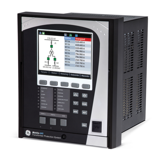
DESCRIPTION OF THE 845 TRANSFORMER PROTECTION RELAY CHAPTER 1: INTRODUCTION Description of the 845 Transformer Protection Relay Relay functions are controlled by two processors: a Freescale MPC5125 32-bit microprocessor that measures all analog signals and digital inputs and controls all output relays, and a Freescale MPC8358 32-bit microprocessor that controls all the advanced Ethernet communication protocols. - Page 11 CHAPTER 1: INTRODUCTION DESCRIPTION OF THE 845 TRANSFORMER PROTECTION RELAY Figure 1-1: Single Line Diagram 845 TRANSFORMER PROTECTION SYSTEM – INSTRUCTION MANUAL 1–3...
- Page 12 DESCRIPTION OF THE 845 TRANSFORMER PROTECTION RELAY CHAPTER 1: INTRODUCTION Table 1-1: ANSI Device Numbers and Functions ANSI Device Description Voltz per hertz Phase Undervoltage Auxiliary Undervoltage Hottest Spot Temperature Aging Factor Loss of Life 50/87 Instantaneous Differential Overcurrent 50BF...
- Page 13 CHAPTER 1: INTRODUCTION DESCRIPTION OF THE 845 TRANSFORMER PROTECTION RELAY Description Output Relays Setpoint Groups (6) Transformer Overload Transformer Loss of Life Trip Bus (6) Transient Recorder (Oscillography) Trip and Close Coil Monitoring User-programmable LEDs User-programmable Pushbuttons Virtual Inputs (32) Virtual Outputs (32) 845 TRANSFORMER PROTECTION SYSTEM –...
-
Page 14: Security Overview
The basic security feature is present in the default offering of the 845 relay. The 845 introduces the notion of roles for different levels of authority. Roles are used as login names with associated passwords stored on the device. The following roles are available at present: Administrator, Operator, Factory and Observer, with a fixed permission structure for each one. - Page 15 CHAPTER 1: INTRODUCTION SECURITY OVERVIEW The 845 can still use the Setpoint access switch feature, but enabling the feature can be done only by an Administrator. Setpoint access is controlled by a keyed switch to offer some minimal notion of security.
-
Page 16: 845 Order Codes
“User Name:” field changes to a drop down menu where the user can select one of the predefined roles on the 845. 845 Order Codes The information to specify an 845 relay is provided in the following Order Code figure: 1–8 845 TRANSFORMER PROTECTION SYSTEM – INSTRUCTION MANUAL... - Page 17 CHAPTER 1: INTRODUCTION 845 ORDER CODES Figure 1-3: Order Codes 845 – E ** ** ** H Interface 845 Transformer Protection Relay Language English Phase NN | Two windings, no voltage Currents 1A three-phase current inputs (J1) with voltage (J2)
-
Page 18: Specifications
Pickup level:............3.00 to 30.00 per unit in steps 0.01 Dropout level: ............97 to 98% of Pickup Operate time:............<12 ms at >3 x Pickup@60Hz <15 ms at >3 x Pickup@50Hz 1–10 845 TRANSFORMER PROTECTION SYSTEM – INSTRUCTION MANUAL... - Page 19 <16 ms typical at 3 × Pickup at 60 Hz (Neutral IOC) <15 ms typical at 3 × Pickup at 50 Hz (Phase/Ground IOC) <20 ms typical at 3 × Pickup at 50 Hz (Neutral IOC) 845 TRANSFORMER PROTECTION SYSTEM – INSTRUCTION MANUAL 1–11...
- Page 20 Dropout Level:............97 to 98% of Pickup Operate Time (no direction transition): ..< 16 ms at 3 x Pickup at 60 Hz < 20 ms at 3 x Pickup at 50 Hz 1–12 845 TRANSFORMER PROTECTION SYSTEM – INSTRUCTION MANUAL...
- Page 21 Operate Time:............<25 ms at 1.1 x slope x Imax at 60 Hz, typically <30 ms at 1.1 x slope x Imax at 50 Hz, typically Timing Accuracy: ..........±3% of delay setting or ± ¼ cycle (whichever is greater) from pickup to operate 845 TRANSFORMER PROTECTION SYSTEM – INSTRUCTION MANUAL 1–13...
- Page 22 Dropout Level:............102 to 103% of Pickup Level Accuracy:............ ± 0.5% of reading from 10 to 208 V Undervoltage Curves:........Definite Time or GE IAV Inverse Time Pickup Time Delay:..........0.000 to 6000.000 s in steps of 0.001 s Operate Time: ............< 20 ms at 0.90 x pickup at 60 Hz <...
- Page 23 Operate Time:............< 55 ms at 1.1 x pickup at 60 Hz < 65 ms at 1.1 x pickup at 50 Hz Timer Accuracy:...........± 3% of delay setting or ± ¼ cycle (whichever is greater) from pickup to operate 845 TRANSFORMER PROTECTION SYSTEM – INSTRUCTION MANUAL 1–15...
- Page 24 95% Settling Time for df/dt: ......< 24 cycles Operate Time: ............typically 10 cycles at 2 × Pickup RTD PROTECTION Pickup:..............1°C to 250°C in steps of 1°C Hysteresis:.............. 2°C Timer Accuracy: ..........<2 s Elements:..............Trip and Alarm 1–16 845 TRANSFORMER PROTECTION SYSTEM – INSTRUCTION MANUAL...
-
Page 25: Control
Timer Accuracy:...........± 3% of delay setting or ± ¼ cycle (whichever is greater) from pickup to operate Monitoring HARMONIC DERATING Timer Accuracy:...........±3% of delay setting or ±3 cycle (whichever is greater) from pickup to operate 845 TRANSFORMER PROTECTION SYSTEM – INSTRUCTION MANUAL 1–17... - Page 26 Pickup Delay: ............0 to 60000 minutes in step of 1 min XFMR LOSS OF LIFE Operating Quantity:........... Computed Accumulated Transformer Loss of Life, hours Pickup Level: ............0 to 300000 hours in steps of 1 hour 1–18 845 TRANSFORMER PROTECTION SYSTEM – INSTRUCTION MANUAL...
-
Page 27: Recording
Pickup delay: ............0 to 60000 (ms, sec., min.) in steps of 1 Dropout delay:............0 to 60000 (ms, sec., min.) in steps of 1 Timer accuracy:........... ±3% of delay setting or ±¼ cycle (whichever is greater) from pickup to operate 845 TRANSFORMER PROTECTION SYSTEM – INSTRUCTION MANUAL 1–19... -
Page 28: Metering
Parameters:............Wye VTs: A-n, B-n, C-n, A-B, B-C, C-A, Average Phase, Neutral and Residual Delta VTs: A-B, B-C, C-A, Neutral and Residual Accuracy:..............± 0.5% of reading from 15 to 208 V ± 1% for open Delta connections 1–20 845 TRANSFORMER PROTECTION SYSTEM – INSTRUCTION MANUAL... - Page 29 I > 0.4 x CT: ± 0.01 Hz (input frequency 15 to 70 Hz) CURRENT AND VOLTAGE HARMONICS Parameters:............Magnitude of each harmonic and THD Range: ..............2 to 25 harmonic: per-phase displayed as % of f fundamental frequency THD: per-phase displayed as % of f 845 TRANSFORMER PROTECTION SYSTEM – INSTRUCTION MANUAL 1–21...
-
Page 30: Inputs
Amplitude Modulation:........1 V to 10 V pk-to-pk DC Shift:..............TTL Input Impedance: ..........40 kΩ Isolation: ..............2 kV Clock Setup:............Date and Time, Daylight Savings Time, UTC (Coordinated Universal Time) Backup Retention: ..........1hour 1–22 845 TRANSFORMER PROTECTION SYSTEM – INSTRUCTION MANUAL... -
Page 31: Outputs
Break (AC resistive): ..........277 VAC / 10 A Operation Mode:..........Self-Reset, Latched, Pulsed, Non-Failsafe, Failsafe Breaking Capacity: ..........For Form-C relays the following ratings are applied to meet UL508 requirements: 1 second “ON”/10 seconds “OFF” per output relay at maximum rating 845 TRANSFORMER PROTECTION SYSTEM – INSTRUCTION MANUAL 1–23... -
Page 32: Power Supply
Parity: ............... None, Odd, Even Protocol:..............Modbus RTU, DNP 3.0, IEC 60870-5-103 Maximum distance:........... 1200 m (4000 feet) Isolation: ..............2 kV WIFI Standard specification:........IEEE802.11bgn Range:..............30 ft (direct line of sight) 1–24 845 TRANSFORMER PROTECTION SYSTEM – INSTRUCTION MANUAL... -
Page 33: Testing & Certification
Level 4 Ingress Protection IEC60529 IP54 front Environmental (Cold) IEC60068-2-1 -40C 16 hrs Environmental (Dry heat) IEC60068-2-2 85C 16hrs Relative Humidity Cyclic IEC60068-2-30 6 day humidity variant 2 IEEE/ANSI C37.90.1 4kV, 5 kHz 845 TRANSFORMER PROTECTION SYSTEM – INSTRUCTION MANUAL 1–25... -
Page 34: Physical
Indicates a hazardous situation which, if not avoided, will result in death or serious DANGER: injury. Indicates a hazardous situation which, if not avoided, could result in death or serious IMPORTANT: injury. 1–26 845 TRANSFORMER PROTECTION SYSTEM – INSTRUCTION MANUAL... -
Page 35: General Cautions And Warnings
1M. Class 1M devices are considered safe to the unaided eye. Do not view directly with optical instruments. To ensure the settings file inside the relay is updated, wait 30 seconds after a setpoint FASTPATH: change before cycling power. 845 TRANSFORMER PROTECTION SYSTEM – INSTRUCTION MANUAL 1–27... -
Page 36: Must-Read Information
Note that the factory role password may not be changed. • In 845 both DNP and IEC104 protocol can work at the same time, but the user has to consider that there is only one point map. So, both protocols use the same configured points. -
Page 37: For Further Assistance
Worldwide telephone: +1 905 927 7070 Europe/Middle East/Africa telephone: +34 94 485 88 54 North America toll-free: 1 800 547 8629 Fax: +1 905 927 5098 Worldwide e-mail: multilin.tech@ge.com Europe e-mail: multilin.tech.euro@ge.com Website: http://www.gedigitalenergy.com/multilin/ 845 TRANSFORMER PROTECTION SYSTEM – INSTRUCTION MANUAL 1–29... - Page 38 FOR FURTHER ASSISTANCE CHAPTER 1: INTRODUCTION 1–30 845 TRANSFORMER PROTECTION SYSTEM – INSTRUCTION MANUAL...
-
Page 39: Product Identification
This section describes the mechanical installation of the system, including dimensions for mounting and information on module withdrawal and insertion. Product Identification The product identification label is located on the side panel of the 845. This label indicates the product model, serial number, and date of manufacture. Figure 2-1: Product Label Dimensions The dimensions (in inches [millimeters]) of the 845 are shown below. -
Page 40: Mounting
Use needle nose pliers to bend the retaining "V" tabs outward to about 90°. Use caution and do not bend and distort the wall of the enclosure adjacent to the tabs. The relay can now be inserted and can be panel wired. 2–2 845 TRANSFORMER PROTECTION SYSTEM – INSTRUCTION MANUAL... -
Page 41: Standard Panel Mount
The standard panel mount and cutout dimensions are illustrated below. To avoid the potential for personal injury due to fire hazards, ensure the unit is CAUTION: mounted in a safe location and/or within an appropriate enclosure. Figure 2-4: Standard panel mount 845 TRANSFORMER PROTECTION SYSTEM – INSTRUCTION MANUAL 2–3... -
Page 42: Draw-Out Unit Withdrawal And Insertion
Turn off control power before drawing out or re-inserting the relay to prevent mal- FASTPATH: operation. Follow the steps outlined in the diagrams below to insert and withdraw the Draw-out unit. 2–4 845 TRANSFORMER PROTECTION SYSTEM – INSTRUCTION MANUAL... -
Page 43: Removable Power Supply
Figure 2-6: Unit withdrawal and insertion diagram Removable Power Supply Follow the steps outlined in the Insert or Remove Power Supply diagram to insert (#1) or remove (#2) the power supply from the unit. 845 TRANSFORMER PROTECTION SYSTEM – INSTRUCTION MANUAL 2–5... -
Page 44: Removable Magnetic Module
Figure 2-7: Insert or Remove the Power Supply Figure 2-8: Unlatch Module (location is marked by arrow) Removable Magnetic Module Follow the steps outlined in the diagram below to insert or remove the magnetic module from the unit. 2–6 845 TRANSFORMER PROTECTION SYSTEM – INSTRUCTION MANUAL... -
Page 45: Electrical Installation
CHAPTER 2: INSTALLATION ELECTRICAL INSTALLATION Figure 2-9: Insert or Remove the Magnetic Module Electrical Installation The following diagram illustrates the electrical wiring of the Draw-out unit. 845 TRANSFORMER PROTECTION SYSTEM – INSTRUCTION MANUAL 2–7... - Page 46 ELECTRICAL INSTALLATION CHAPTER 2: INSTALLATION Figure 2-10: Typical Wiring Diagram for a 2-Winding Transformer with VTs on HV Side 2–8 845 TRANSFORMER PROTECTION SYSTEM – INSTRUCTION MANUAL...
- Page 47 CHAPTER 2: INSTALLATION ELECTRICAL INSTALLATION Figure 2-11: Typical Wiring Diagram for a 2-Winding Transformer with VTs on LV Side 845 TRANSFORMER PROTECTION SYSTEM – INSTRUCTION MANUAL 2–9...
- Page 48 ELECTRICAL INSTALLATION CHAPTER 2: INSTALLATION Figure 2-12: Typical Wiring Diagram for a 2-Winding Transformer without VTs 2–10 845 TRANSFORMER PROTECTION SYSTEM – INSTRUCTION MANUAL...
- Page 49 CHAPTER 2: INSTALLATION ELECTRICAL INSTALLATION Figure 2-13: Typical Wiring Diagram for a 3-Winding Transformer 845 TRANSFORMER PROTECTION SYSTEM – INSTRUCTION MANUAL 2–11...
-
Page 50: Terminal Identification
This is to ensure the adjacent lower terminal block does not interfere with the lug body. Figure 2-14: Orient the Lugs Correctly SCREW WASHER LOWER TERMI AL TERMI AL BLOCK DIVIDER Figure 2-15: Correct Installation Method 2–12 845 TRANSFORMER PROTECTION SYSTEM – INSTRUCTION MANUAL... - Page 51 ELECTRICAL INSTALLATION Figure 2-16: INCORRECT INSTALLATION METHOD (lower lug reversed) A broad range of applications are available for the 845 relays. As such, it is not possible to present typical connections for all possible schemes. The information in this section covers the important aspects of interconnections, in the general areas of instrument transformer inputs, other inputs, outputs, communications and grounding.
- Page 52 1E/1P/2E - Comms - Advanced Ethernet Terminal Description Terminal Description IRIG + IRIG + IRIG - IRIG - RS485_1 (+) RS485_1 (+) RS485_1 (-) RS485_1 (-) RS485_1 COM RS485_1 COM RESERVED RESERVED 2–14 845 TRANSFORMER PROTECTION SYSTEM – INSTRUCTION MANUAL...
- Page 53 Critical Fail Relay FC_3 NO Critical Fail Relay Table 2-4: AC Analog AC Inputs - 4 X 1/5A CT, 4 VT Terminal Description CT1_IN CT1_RETURN CT2_IN CT2_RETURN CT3_IN CT3_RETURN CT4_IN CT4_RETURN VT1_IN 845 TRANSFORMER PROTECTION SYSTEM – INSTRUCTION MANUAL 2–15...
-
Page 54: Wire Size
The phase sequence is user programmable for either ABC or ACB rotation. The 845 relay has four (4) current inputs in each J slot and K slot. Three of them are used for connecting to the phase CT phases A, B, and C. The fourth input is a ground input that can be connected to either a ground CT placed on the neutral from a Wye connected transformer winding, or to a “donut”... -
Page 55: Ground Ct Inputs
Figure 2-19: Ground Inputs Voltage Inputs The 845 relays have four channels for AC voltage inputs, each with an isolating transformer. Voltage transformers up to a maximum 5000:1 ratio may be used. The nominal secondary voltage must be in the 10 to 240 V range. The Bus VT connections most commonly used, wye and delta (or open delta), are shown in the typical wiring diagram. -
Page 56: Restricted Earth Fault Inputs
The figure below shows the various CT connections and the exact placement of a Zero Sequence current CT, so that ground fault current can be detected. Twisted pair cabling on the Zero Sequence CT is recommended. 2–18 845 TRANSFORMER PROTECTION SYSTEM – INSTRUCTION MANUAL... -
Page 57: Control Power
A tinned copper, braided, shielding and bonding cable should be used. As a minimum, 96 strands of number 34 AWG should be used. Belden catalog number 8660 is suitable. Figure 2-23: Control Power Connection 845 TRANSFORMER PROTECTION SYSTEM – INSTRUCTION MANUAL 2–19... -
Page 58: Contact Inputs
Wet or Dry input signal types can be connected to contact input terminals as shown in the figure: Wet and Dry Contact Input Wiring Examples. Dry inputs use an internal +24V that is supplied by the 845. The voltage threshold must be set to 17V for the inputs to be recognized using the internal +24V. - Page 59 RELAY_4 AUX 4 RELAY_12 AUX 4 RELAY_4 AUX 4 RELAY_12 AUX 4 RELAY_4 AUX 4 RELAY_12 AUX 4 RELAY_5 RELAY_13 RELAY_5 RELAY_13 RELAY_5 RELAY_13 RELAY_6 RELAY_14 RELAY_6 RELAY_14 RELAY_6 RELAY_14 RELAY_7 RELAY_15 845 TRANSFORMER PROTECTION SYSTEM – INSTRUCTION MANUAL 2–21...
-
Page 60: Serial Communications
CAUTION: that the common terminals of each RS485 port are tied together and grounded only once, at the master or at the 845. Failure to do so may result in intermittent or failed communications. The source computer/PLC/SCADA system should have similar transient protection devices installed, either internally or externally. -
Page 61: Irig-B
DC level shift or amplitude modulated (AM) form. The type of form is auto-detected by the 845 relay. Third party equipment is available for generating the IRIG-B signal; this equipment may use a GPS satellite system to obtain the time reference so that devices at different geographic locations can also be synchronized. - Page 62 ELECTRICAL INSTALLATION CHAPTER 2: INSTALLATION 2–24 845 TRANSFORMER PROTECTION SYSTEM – INSTRUCTION MANUAL...
- Page 63 • Interfacing via the EnerVista 8 Series Setup software. This section provides an overview of the interfacing methods available with the 845 using the relay control panel and EnerVista 8 Series Setup software. For additional details on interface parameters (for example, settings, actual values, etc.), refer to the individual chapters.
- Page 64 Pressing the Menu key during the display of the default message, returns the display to the last message shown before the default message appeared. Any Trip, Alarm, or Pickup is displayed immediately, automatically overriding the default message. 3–2 845 TRANSFORMER PROTECTION SYSTEM – INSTRUCTION MANUAL...
-
Page 65: Interfaces Front Control Panel Interface
The display contains five main menu items labeled Targets, Status, Metering, Setpoints, Graphical Display and Records located at the bottom of the screen. Choosing each main menu item displays the corresponding sub-menu. Pages 845 TRANSFORMER PROTECTION SYSTEM – INSTRUCTION MANUAL 3–3... - Page 66 CHAPTER 3: INTERFACES Figure 3-3: Typical paging operation from the Main Menu There are two ways to navigate throughout the 845 menu: using the pushbuttons corresponding to the soft tabs from the screen, or by selecting the item from the list of items on the screen using the “Up”...
- Page 67 The Escape pushbutton is used to display the previous menu. This pushbutton can also be used to cancel a setpoint change. The Reset pushbutton clears all latched LED indications, target messages, and latched output relays, providing the conditions causing these events are not present. 845 TRANSFORMER PROTECTION SYSTEM – INSTRUCTION MANUAL 3–5...
-
Page 68: Led Status Indicators
• Reset mode: self-reset or latched The 845 front panel provides two columns of 7 LED indicators each, and 3 LED pushbutton indicators. The “IN-SERVICE” (LED 1) and the “PICKUP” (LED 4) indicators from the first LED column are non-programmable LEDs. The bottom 3 LED indicators from the first column, and the 7 LED indicators from the second LED column are fully programmable. -
Page 69: Home Screen Icons
Support for applying a customized label beside every LED is provided. Default labels are shipped in the label package of every 845 together with custom templates. The default labels can be replaced by user-printed labels. User customization of LED operation has maximum benefit in installations where languages other than English are used to communicate with operators. -
Page 70: Relay Messages
If no further navigation is performed, no pushbutton is touched, and/or no target is initiated for the time specified in the message timeout setpoint, the display goes back to the default screen (the metering summary screen). 3–8 845 TRANSFORMER PROTECTION SYSTEM – INSTRUCTION MANUAL... -
Page 71: Self-Test Errors
Displays “Major Self-test error” with the error code as a target message • Records the major self-test failure in the Event Recorder Under both conditions, the targets cannot be cleared if the error is still active. Figure 3-9: Minor Errors 845 TRANSFORMER PROTECTION SYSTEM – INSTRUCTION MANUAL 3–9... - Page 72 CPU and LEDs, Keypad or peripheral memory devices Invalid MAC MAC address is not in Every 1 second Address the product range Calibration Error Unit has default Boot-up and Every 1 calibration values second 3–10 845 TRANSFORMER PROTECTION SYSTEM – INSTRUCTION MANUAL...
- Page 73 1. – Failure is logged after the detection of 5 consecutive failures 2. $ – is the slot ID (i.e., F, G, H etc.) 3.To disable Link Error Primary target when not in-use with SE order code, change IP address to 0.0.0.0 845 TRANSFORMER PROTECTION SYSTEM – INSTRUCTION MANUAL 3–11...
-
Page 74: Flash Messages
The factory default flash message time is 4 seconds. Label Removal The following procedure describes how to use the label removal tool. Bend the tabs of the tool upwards as shown in the image. 3–12 845 TRANSFORMER PROTECTION SYSTEM – INSTRUCTION MANUAL... -
Page 75: Software Interface
Although settings can be entered manually using the control panel keys, a PC can be used to download setpoints through the communications port. The EnerVista 8 Series Setup software is available from GE Multilin to make this as convenient as possible. With EnerVista 8 Series Setup software running, it is possible to: 845 TRANSFORMER PROTECTION SYSTEM –... -
Page 76: Hardware & Software Requirements
The EnerVista 8 Series Setup software can run without a 845 connected to the computer. In this case, settings may be saved to a file for future use. If a 845 is connected to a PC and communications are enabled, the 845 can be programmed from the setting screens. In addition, measured values, status and trip messages can be displayed with the actual value screens. - Page 77 EnerVista 8 Series Setup software to the Windows start menu. The 845 device is added to the list of installed IEDs in the EnerVista Launchpad window, as shown below. 845 TRANSFORMER PROTECTION SYSTEM – INSTRUCTION MANUAL...
- Page 78 If you are going to communicate from your computer to the 845 Relay using the USB port: 10. Plug the USB cable into the USB port on the 845 Relay then into the USB port on your computer. 11. Launch EnerVista 8 Series Setup software from LaunchPad.
-
Page 79: Connecting Enervista 8 Series Setup Software To The Relay
USB is selected in the interface drop-down list. Select “USB” and press the Connect button. Ethernet or WiFi can also be used as the interface for Quick Connect as shown next. 845 TRANSFORMER PROTECTION SYSTEM – INSTRUCTION MANUAL 3–17... -
Page 80: Configuring Ethernet Communications
FASTPATH: Install and start the latest version of the EnerVista 8 Series Setup software (available from the GE EnerVista CD or Website). See the previous section for the installation procedure. Click on the Device Setup button to open the Device Setup window and click the Add Site button to define a new site. -
Page 81: Connecting To The Relay
Enter the IP address, slave address, and Modbus port values assigned to the 845 relay (from the SETPOINTS > DEVICE > COMMUNICATIONS menu). Click the Read Order Code button to connect to the 845 and upload the order code. If a communications error occurs, ensure that the Ethernet communication values correspond to the relay setting values. -
Page 82: Working With Setpoints & Setpoints Files
Select the Setpoint > System > Voltage Sensing menu item. Select the Aux. VT Secondary setpoint by clicking anywhere in the parameter box. This displays three arrows: two to increment/decrement the value and another to launch the numerical keypad. 3–20 845 TRANSFORMER PROTECTION SYSTEM – INSTRUCTION MANUAL... - Page 83 For setpoints requiring non-numerical pre-set values (e.g. Phase VT Connection below), clicking anywhere within the setpoint value box displays a drop-down selection menu arrow. Select the desired value from this list. 845 TRANSFORMER PROTECTION SYSTEM – INSTRUCTION MANUAL 3–21...
-
Page 84: File Support
In the Setpoints > System Setup > Voltage Sensing dialog box, click on Save to save the values into the 845. Click YES to accept any changes and exit the window. Click Restore to retain previous values. Click Default to restore Default values. -
Page 85: Downloading & Saving Setpoints Files
The software allows the user to create new setpoint files independent of a connected Setpoints File device. These can be uploaded to a relay at a later date. The following procedure illustrates how to create new setpoint files. 845 TRANSFORMER PROTECTION SYSTEM – INSTRUCTION MANUAL 3–23... -
Page 86: Upgrading Setpoints Files To A New Revision
Select the file name and path to store the file, or select any displayed file name to replace an existing file. All 845 setpoint files should have the extension ‘.cid’ (for example, ‘845 1.cid’). Click OK to complete the process. Once this step is completed, the new file, with a complete path, is added to the 845 software environment. -
Page 87: Printing Setpoints
If printing from an online device, select the Online > Print Device Information menu item. If printing from a previously saved setpoints file, select the Offline > Print Settings File menu item. 845 TRANSFORMER PROTECTION SYSTEM – INSTRUCTION MANUAL 3–25... -
Page 88: Printing Values From A Connected Device
OK. Actual values lists can be printed in the same manner by right clicking on the desired device (in the device list) and selecting the Print Device Information option. 3–26 845 TRANSFORMER PROTECTION SYSTEM – INSTRUCTION MANUAL... -
Page 89: Loading Setpoints From A File
The following procedure illustrates how to load setpoints from a file. Before loading a setpoints file, it must first be added to the 845 environment as described in the section, Adding Setpoints Files to the Environment. - Page 90 SOFTWARE INTERFACE CHAPTER 3: INTERFACES Figure 3-11: 845 Quick Setup (Online) tree position Figure 3-12: 845 Quick Setup (Offline) tree position Quick Setup is designed to allow quick and easy user programming. Power system parameters, and settings for some simple overcurrent elements are easily set. The Quick Setup screen is shown as follows: 3–28...
- Page 91 • The user can configure and save the settings as required. • The Save, Restore and Default buttons function the same as in the individual setting setup screens. 845 TRANSFORMER PROTECTION SYSTEM – INSTRUCTION MANUAL 3–29...
-
Page 92: Upgrading Relay Firmware
Note that uploading firmware to a relay having a Communications card must be done with “Port 4 operation” configured as independent. Before upgrading firmware, it is very important to save the current 845 settings to a file on FASTPATH: your PC. After the firmware has been upgraded, it will be necessary to load this file back into the 845. - Page 93 The 845 front panel momentarily displays “Upload Mode”, indicating that it is in upload mode. While the file is being loaded into the 845 , a status box appears showing how much of the new firmware file has been transferred and the upgrade status. The entire transfer process takes up to 30 minutes.
-
Page 94: Advanced Enervista 8 Series Setup Software Features
SOFTWARE INTERFACE CHAPTER 3: INTERFACES After successfully updating the 845 firmware, the relay is not in service and requires setpoint programming. To communicate with the relay, the communication settings may have to be manually reprogrammed. When communications is established, the saved setpoints must be reloaded back into the relay. - Page 95 CHAPTER 3: INTERFACES SOFTWARE INTERFACE 845 TRANSFORMER PROTECTION SYSTEM – INSTRUCTION MANUAL 3–33...
-
Page 96: Transient Recorder (Waveform Capture)
• The user can load Trip Times from a CSV File • The screen above shows the model followed by 845 for viewing FlexCurves. Select Initialize to copy the trip times from the selected curve to the FlexCurve. Transient Recorder... - Page 97 "CFG." The other file is a "DAT" file, required by the COMTRADE file for proper display of waveforms. • To view a previously saved COMTRADE file, click the Open button and select the corresponding COMTRADE file. 845 TRANSFORMER PROTECTION SYSTEM – INSTRUCTION MANUAL 3–35...
- Page 98 • From the window main menu bar, press the Preference button to open the COMTRADE Setup page, in order to change the graph attributes. 3–36 845 TRANSFORMER PROTECTION SYSTEM – INSTRUCTION MANUAL...
- Page 99 The Waveform Capture window reappears based on the selected graph attributes. To view a vector graph of the quantities contained in the waveform capture, press the View Phasors button to display the following window: 845 TRANSFORMER PROTECTION SYSTEM – INSTRUCTION MANUAL 3–37...
-
Page 100: Protection Summary
With the software running and communications established, select the Setpoints > Protection Summary menu item to open the Protection Summary window. The Protection Summary screen is as follows: 3–38 845 TRANSFORMER PROTECTION SYSTEM – INSTRUCTION MANUAL... -
Page 101: Offline Settings File Conversion
The EnerVista 8 Series Setup software reduces the manual effort required when moving from an older product to the 845. The feature takes an existing settings file provided by the user and generates a new settings file compatible with the 8 Series order code specified by the user. -
Page 102: Conversion Summary Report
At the end of the conversion process, the results are summarized in a conversion report. Report The report is found under Device Definition in the offline file window. Figure 3-14: Conversion Report in Offline Window 3–40 845 TRANSFORMER PROTECTION SYSTEM – INSTRUCTION MANUAL... -
Page 103: Results Window
Value is not supported If desired, the conversion summary report can be printed using the File/Print Print Report command in the EnerVista taskbar or it can be printed from the “GUI” print button. 845 TRANSFORMER PROTECTION SYSTEM – INSTRUCTION MANUAL 3–41... - Page 104 SOFTWARE INTERFACE CHAPTER 3: INTERFACES 3–42 845 TRANSFORMER PROTECTION SYSTEM – INSTRUCTION MANUAL...
- Page 105 Setpoints Setpoints Main Menu The 845 has a considerable number of programmable setpoints, all of which make the relay extremely flexible. These setpoints have been grouped into a variety of menus as shown below. Each setpoints menu has sub-sections that describe in detail the setpoints found on that menu.
-
Page 106: Setpoints Setpoints Main Menu
Figure 4-2: Main Setpoints Screen Protection and Trip Breaker Selection Depending on order code, the 845 relay provides protection for either two-winding, or three-winding transformers. Based on this, either two or three breakers can be configured for status monitoring, tripping and closing. Each breaker menu provides a selection of trip output and/or close output relay. - Page 107 From the Relay HMI: Protection Element Menu • From the 845 PC program: Element’s Menu or Protection Summary From the Relay HMI: Protection Element Menu If Trip is selected as a “Function” for an element, and upon operation of that element, the LED “TRIP”...
- Page 108 IOC1 menu to be programmable. From 845 PC Program: Element Menu or Protection Summary Using the 845 PC program, there are two places where the menu of each protection, control, or monitoring element can be accessed: The element’s individual menu, and the Protection Summary menu.
- Page 109 When Alarm, Latched Alarm or Configurable is selected as a Function, the Output Relays 1 and 2, which have been assigned to trip Breaker 1 and 2 respectively, are de- activated for operation. 845 TRANSFORMER PROTECTION SYSTEM – INSTRUCTION MANUAL 4–5...
-
Page 110: Setpoints Entry Methods
Front USB port, connected to a portable computer running the EnerVista 8 Series Setup software. • Rear Ethernet (copper or fiber port connected to portable computer running the EnerVista 8 Series Setup software. 4–6 845 TRANSFORMER PROTECTION SYSTEM – INSTRUCTION MANUAL... -
Page 111: Common Setpoints
Files can be stored and downloaded for fast, error free entry when a computer is used. To facilitate this process, the GE EnerVista CD with the EnerVista 8 Series Setup software is supplied with the relay. The relay leaves the factory with setpoints programmed to default values, and it is these values that are shown in all the setpoint message illustrations. -
Page 112: Logic Diagrams
845 relay. The targets disappear from the screen when “Self-Reset” is selected, and the conditions are cleared. The targets stay on the screen, when “Latched” is selected, and the conditions are cleared. -
Page 113: Setpoints Text Abbreviations
Hz: Hertz • MAX: maximum • MIN: minimum • SEC, s: seconds • UV: undervoltage • OV: overvoltage • VT: voltage transformer • Ctrl: control • Hr & hr: hour • O/L: overload 845 TRANSFORMER PROTECTION SYSTEM – INSTRUCTION MANUAL 4–9... -
Page 114: Device
PTP and IRIG-B can be swapped. If both PTP and IRIG-B are available to the 845, by default the 845 clock syncs to PTP over IRIG-B. If PTP is not available the 845 CPU syncs the internal clock to IRIG-B. -
Page 115: Clock
DST START HOUR Range: 0 to 23 Default: 2 DST END MONTH Range: January to December (all months) Default: Not Set DST END WEEK Range: 1st, 2nd, 3rd, 4th, Last Default: Not Set 845 TRANSFORMER PROTECTION SYSTEM – INSTRUCTION MANUAL 4–11... -
Page 116: Ptp Configuration
Range: Disabled, Enabled Default: Enabled When the port setting is selected as “Disabled,” PTP is disabled on the port. The relay does not generate, or listen to, PTP messages on the port. 4–12 845 TRANSFORMER PROTECTION SYSTEM – INSTRUCTION MANUAL... - Page 117 A network may support multiple time distribution domains, each distinguished with a unique domain number. More commonly, there is a single domain using the default domain number zero. The setting applies to all of the relay’s PTP-capable ports. 845 TRANSFORMER PROTECTION SYSTEM – INSTRUCTION MANUAL 4–13...
-
Page 118: Sntp Protocol
CyberSentry – The feature refers to the advanced security options available as a software option. When this option is purchased, it is automatically enabled and Basic Security is disabled. GENERAL RULES FOR ROLES 4–14 845 TRANSFORMER PROTECTION SYSTEM – INSTRUCTION MANUAL... - Page 119 - Non-alphabetic characters (for example, ~, !, @, #, $,%, &) PASSWORD RECOVERY PROCEDURE In the event of losing all passwords, the 845 can be reset to factory defaults by following the procedure below: The customer sends an email to the customer support department providing a valid serial number and using a recognizable corporate email account.
-
Page 120: Basic Security
If password complexity is enabled, the rules as defined in the Password Complexity section must be obeyed. If password complexity is disabled this setting accepts 1 to 20 alphanumeric characters. PATH: SEPTPOINTS > DEVICE > SECURITY > CHANGE LOCAL PASSWORDS 4–16 845 TRANSFORMER PROTECTION SYSTEM – INSTRUCTION MANUAL... - Page 121 The authentication lockout has occurred because of too many failed authentication attempts. LOGIN An event meant to indicate when a certain role logged LOGOUT An event meant to indicate when a certain role logged out or timed out. 845 TRANSFORMER PROTECTION SYSTEM – INSTRUCTION MANUAL 4–17...
-
Page 122: Cybersentry
IEC 61850) without user authentication or encryption of data taking place, even if the relay has the advanced security feature enabled. SECURITY SETTINGS STRUCTURE The figure below shows the location of the Security settings in the device display hierarchy. 4–18 845 TRANSFORMER PROTECTION SYSTEM – INSTRUCTION MANUAL... - Page 123 If the user enters the wrong password, the “Authentication Failed!” message is displayed. – If the maximum failed authentications occur, the “Account Blocked!” message is displayed. – The Observer user role is the default choice and it does not require a password. 845 TRANSFORMER PROTECTION SYSTEM – INSTRUCTION MANUAL 4–19...
- Page 124 The Access timeout is the time of idleness before a logged in user is automatically logged out. This timeout setting applies to all users, independent of the communication channel (serial, Ethernet or direct access). 4–20 845 TRANSFORMER PROTECTION SYSTEM – INSTRUCTION MANUAL...
- Page 125 – The default password is “0”. – The Observer does not have a password associated with it. So there is no need to show it in the list of password changing roles. 845 TRANSFORMER PROTECTION SYSTEM – INSTRUCTION MANUAL 4–21...
- Page 126 The following are settings that need to be configured through EnerVista, in order to set up communication with a Radius server on 845. For configuring the RADIUS server itself, consult the RADIUS documentation. An example is provided, see Communications Guide.
- Page 127 Warning (4) An event to indicate when a certain role logged out or timed out. RADIUS_UNREACH, ORIGIN, Critical (2) RADIUS server is unreachable. Origin: RADIUS TIMESTAMP: server IP address and port number. 845 TRANSFORMER PROTECTION SYSTEM – INSTRUCTION MANUAL 4–23...
-
Page 128: Communications
SNTP protocol. RS485 On the rear card the 845 is equipped with one RS485 serial communication port and one 10/100 Mbps Ethernet port. The RS485 port has settings for baud rate and parity. It is important that these parameters agree with the settings used on the computer or other equipment connected to this port. - Page 129 WiFi IP Address / Subnet Mask The default IP address is 192.168.0.x, where x is calculated as: X = (modulo 252 of the last 3 digits of the serial number) + 12 845 TRANSFORMER PROTECTION SYSTEM – INSTRUCTION MANUAL 4–25...
- Page 130 8-Series device. When choosing a new passphrase, the password complexity rules of CyberSentry must be used (see CyberSentry details in the 845 Instruction manual). This field is visible only if the security is set to WPA2-PSK.
- Page 131 Start EnerVista on a PC and use the Discover function, all relays within range appear and are populated in Enervista for initial configuration and commissioning. Once the relay is configured, change the 8-Series relay default WiFi SSID and Passphrase settings before the relay goes into service. 845 TRANSFORMER PROTECTION SYSTEM – INSTRUCTION MANUAL 4–27...
-
Page 132: Usb
Whenever the device is rebooted, the USB cable needs to be unplugged and plugged in FASTPATH: again for proper communication to be established over USB. Connecting multiple 845 relays over USB to a single PC is not possible because in the case FASTPATH: of USB, the IP address of the device 172.16.0.2 is constant. - Page 133 When enabled on an 8 Series fiber optic port, this feature is able to detect a failure of the fiber link. If port 4’s OPERATION is set to LLA, the detection of a link failure by this 845 TRANSFORMER PROTECTION SYSTEM – INSTRUCTION MANUAL 4–29...
-
Page 134: Modbus Protocol
When a ModBus master such as the EnerVista 8 Series Setup software communicates to the 845 over Ethernet, the 845 slave address, TCP port number and the 845 IP address for the associated port must be configured and are also configured within the Master for this device. - Page 135 Range: 1 to 254 in steps of 1 Default: 254 For the RS485 ports each 845 must have a unique address from 1 to 254. Address 0 is the broadcast address to which all Modbus slave devices listen. Addresses do not have to be sequential, but no two devices can have the same address, otherwise conflicts resulting in errors occur.
- Page 136 Modbus Implementation: Read Input Registers 845 Implementation: Read Actual Values For the 845 implementation of Modbus, the function code can be used to read any actual values (“input registers”). Input registers are 16 bit (two byte) values transmitted high order byte first.
- Page 137 Modbus Implementation: Preset Single Register 845 Implementation: Store Single Setpoint The command allows the master to store a single setpoint into the memory of a 845 relay. The slave response to this function code is to echo the entire master transmission.
- Page 138 Function Code 08H Modbus Implementation: Loopback 845 Implementation: Loopback Test The function is used to test the integrity of the communication link. The 845 echos the request. For example, consider a loopback test from slave 17: Table 4-16: Master Packet Format for Function Code 08H...
- Page 139 Modbus allows up to a maximum of 60 holding registers to be stored. The 845 response to this function code is to echo the slave address, function code, starting address, the number of Setpoints stored, and the CRC.
- Page 140 Modbus Function 10H (Store Multiple Setpoints). The 4 bytes are the function and the command values. The function value is always 05. Table 4-23: Modbus Commands registers Description Memory Map Address Command Register 40129 0x0080 Command Function Register 40130 0x0081 4–36 845 TRANSFORMER PROTECTION SYSTEM – INSTRUCTION MANUAL...
- Page 141 Value Description Reset Clear All Records Clear Events Clear Energy Use Data 4096 Force Virtual Input 1 Table 4-30: Function Format for Reset command Slave # Function Operation Code Code Value 0001 FF00 845 TRANSFORMER PROTECTION SYSTEM – INSTRUCTION MANUAL 4–37...
- Page 142 The 845 supports Distributed Network Protocol (DNP) version 3.0. and the 845 operates as a DNP slave device. Two DNP masters can actively communicate with the 845 at one time as the 845 maintains two sets of DNP data change buffers and connection information.
- Page 143 16-bit integer value without flag 32-bit floating point value with flag Path: Setpoints > Device > Communications > DNP Protocol DNP CHANNEL 1 PORT Range: NONE, NETWORK - TCP, NETWORK- UDP Default: NONE 845 TRANSFORMER PROTECTION SYSTEM – INSTRUCTION MANUAL 4–39...
- Page 144 DNP NETWORK CLIENT ADDRESS 1(2) Range: Standard IP Address Default: 0.0.0.0 The DNP Network Client Address settings can force the 845 to respond to a maximum of two specific DNP masters. DNP TCP/UDP PORT NUMBER 1 (2) Range: 1 to 65535 in steps of 1...
- Page 145 0 is requested and/or in class 0, 1, 2, or 3 scans. The DNP binary outputs typically map one-to-one to IED data points. That is, each DNP binary output controls a single physical or virtual control point in an IED. In the 845 relay, DNP binary outputs are mapped to virtual inputs.
-
Page 146: Dnp / Iec104 Point Lists
DNP TCP connection for greater than the time specified by the setting, the connection is aborted by the 845. This frees up the resource for the connection and allows another DNP TCP connection request. - Page 147 For example, to trigger unsolicited responses from the 845 when phase A current changes by 15 A, the DNP CURRENT DEADBAND for Phase A current should be set to “15”. Note that these settings are the deadband default values.
- Page 148 When a freeze function is performed on a Binary Counter point, the frozen value is available in the corresponding Frozen Counter point. 845 Digital Counter values are represented as 16 or 32-bit integers. The DNP 3.0 protocol defines counters to be unsigned integers.
-
Page 149: Iec 60870-5-104
The IEC 60870-5-104 communications protocol is supported on Ethernet ports 4 and 5 only. Setting changes become active after rebooting. In 845 both DNP and IEC104 protocol can work at the same time, but the user has to FASTPATH: consider that there is only one point map. So, the two protocols use the same data mapping, i.e., same point index and same point source. - Page 150 M_ME_NB_1 analog data. Each setting represents the threshold value for each M_ME_NB_1 analog point. For example, to trigger spontaneous responses from the 845 when a current value changes by 15 A, the “Analog Point xx Deadband” setting should be set to 15. Note that these settings are the default values of the deadbands.
-
Page 151: Iec 60870-5-103
DNP3.0, IEC 103 or Modbus can run on the RS485 serial port. Path: Setpoints > Device > Communications > IEC60870-5-103 To view the list of binary inputs, see the 845 Flexlogic Operands table in the Setpoints/ FlexLogic section of the 845 instruction manual. 845 TRANSFORMER PROTECTION SYSTEM – INSTRUCTION MANUAL... -
Page 152: Iec 61850
Setup software. A rebooting MUST be done before any changes made take affect. The IEC 61850 Configurator The 845 relay supports the IEC 61850 protocol which is identified by order code option “2A” or “2E”. The IEC 61850 configurator is found in both the online and offline section of the EnerVista 8 Series Setup software for configuring the online 845 relay and offline 845 settings file respectively. - Page 153 “fail” IEC 61850 connections. The timer must be application specific for IEC 61850. If there is no data traffic on an established TCP connection for more than this setting time, the connection is disconnected from the 845 TRANSFORMER PROTECTION SYSTEM – INSTRUCTION MANUAL 4–49...
- Page 154 The user can choose either port or both of the ports for GOOSE transmissions and Receptions. The logical nodes displayed under the GEDevice > 845 tree (see figure below) are shown based on the order code. If a particular order code does not support certain protection and control functions, the respective logical node is not shown in the list.
- Page 155 = Phase VT Ratio * 240 min = 0 max = Phase VT Ratio * 240 min = 0 A$phsA, phsB, phsC max = (Phase CT Primary * 46) min = 0 845 TRANSFORMER PROTECTION SYSTEM – INSTRUCTION MANUAL 4–51...
- Page 156 XCBR-POS can be configured for status only, Direct operate, Select before operate, Direct operate with enhanced, SBO enhanced. Reports The Reports tab in IEC 61580 Configurator permits configuration of data sets and report control blocks for buffered and unbuffered reports. 4–52 845 TRANSFORMER PROTECTION SYSTEM – INSTRUCTION MANUAL...
- Page 157 Figure 4-13: Report Control Blocks and DataSet Sources Screen The following buttons are available in the Reports window. • “Add Report” button and “Remove Report” button: Both buttons are in the lower side of the screen. 845 TRANSFORMER PROTECTION SYSTEM – INSTRUCTION MANUAL 4–53...
- Page 158 DEVICE CHAPTER 4: SETPOINTS • Note that a Report control block can also be added by right clicking on “845” which is under the GEDevice “tree”. The “Remove Report” button deletes an existing Report control block. Note that the Report can also be deleted by right clicking on the configured existing report.
- Page 159 “Report Advanced Configuration”. Respective OptFields, TrgOps can be configured by either selecting “True” or “False”. Buffer time is given in milliseconds. Figure 4-17: Advanced Configuration Configure Dataset Items Select the required logical node under GEDevice > 845 tree. 845 TRANSFORMER PROTECTION SYSTEM – INSTRUCTION MANUAL 4–55...
- Page 160 The following list gives the two methods that can be used to delete a dataset item. • Select the row in which the dataset item is to be deleted and click the “x” button. Figure 4-20: Delete a Dataset Item 4–56 845 TRANSFORMER PROTECTION SYSTEM – INSTRUCTION MANUAL...
- Page 161 Buffered Report Unbuffered Report Total Reports Goose Transmission The 845 relay has an IEC 61850 server and supports the GOOSE message scheme. A maximum of three GOOSE control blocks can be added. The GOOSE Configuration has two sections: • Transmission •...
- Page 162 (upper or lower case). The rest of the characters must be a number, a letter (upper or lower case) or a “_”. The maximum number of characters allowed is 32. – Description: The maximum number of characters allowed is 32. 4–58 845 TRANSFORMER PROTECTION SYSTEM – INSTRUCTION MANUAL...
- Page 163 • Note that a GOOSE Control block can also be added by right clicking on “845 ” which is under the GEDevice “tree”. The “Remove Goose Control Block” button deletes a configured existing Goose control block.
- Page 164 Click the Cancel button to discard the modifications just made to the configuration. Add GOOSE Transmission Control Block Click on the “Add GOOSE Control Block” button. The Tx GOOSE control block is added under GEDevice>845 tree node with a default Control block name. Figure 4-25: Goose TX Control Blocks...
- Page 165 Select the row in which the dataset item is to be deleted then right click and select the displayed “Delete FCDA” option. Figure 4-29: Delete FCDA Option Number of DAs Depending on the configured dataset items, the “Number of DAs” counter increases automatically. 845 TRANSFORMER PROTECTION SYSTEM – INSTRUCTION MANUAL 4–61...
- Page 166 Figure 4-30: Dataset Properties Goose Reception The 845 relay can receive Transmitted GOOSE from any IED in “GOOSE Reception”. For proper GOOSE reception the relay must be configurated as described in this section. A maximum of eight IEDs can be added.
-
Page 167: Transient Recorder
Depending on the configured dataset items for IEDs, the IED count increases automatically. In addition, the ”GOOSE Id” field is updated with the GOOSE ID of the subscriber relay. Figure 4-34: IED Count Transient Recorder Path: Setpoints > Device > Transient Recorder 845 TRANSFORMER PROTECTION SYSTEM – INSTRUCTION MANUAL 4–63... - Page 168 Number of Records Sample Rate Analog Channels Length-Cycles 1127 1503 4–64 845 TRANSFORMER PROTECTION SYSTEM – INSTRUCTION MANUAL...
- Page 169 TRIGGER ON ANY OP: Range: On, Off Default: Off Selection of “On” setting enables triggering of the recorder upon operate state of any of the enabled protection or control elements. 845 TRANSFORMER PROTECTION SYSTEM – INSTRUCTION MANUAL 4–65...
-
Page 170: Data Logger
If data is not available for the entire duration of pre-trigger, the trigger position will be NOTE: based on available pre-trigger. 4–66 845 TRANSFORMER PROTECTION SYSTEM – INSTRUCTION MANUAL... - Page 171 Clear Records menu. The table below shows an example on the dependency of the data logger storage capacity with respect to the selected number of channels, and the selected rate (time interval) at which the logged values are taken. The Data Logger 845 TRANSFORMER PROTECTION SYSTEM – INSTRUCTION MANUAL 4–67...
- Page 172 “Rate”. The mean (average) is calculated simply using the well known ratio between the sum of all the values and their number over the time interval. 4–68 845 TRANSFORMER PROTECTION SYSTEM – INSTRUCTION MANUAL...
-
Page 173: Fault Reports
Active setting group at the time of pre-fault trigger • Active setting group at the time of fault trigger. The fault report continuous with the following information: • All current and voltage phasors (one cycle after the fault trigger) 845 TRANSFORMER PROTECTION SYSTEM – INSTRUCTION MANUAL 4–69... -
Page 174: Flex State
These settings specify an actual value such as voltage or current magnitude, true RMS, phase angle, frequency, temperature, etc., to be stored should the report be created. Up to 32 analog channels can be configured. Flex State Path: Setpoints > Device > Flex States 4–70 845 TRANSFORMER PROTECTION SYSTEM – INSTRUCTION MANUAL... -
Page 175: Programmable Leds
PARAMETER 1 (to 256) Range: Off, Any operand from the list of FlexLogic operands, any digital input, any virtual input, any remote input Default: Off Programmable LEDs Path: Setpoints > Device > Programmable LEDs 845 TRANSFORMER PROTECTION SYSTEM – INSTRUCTION MANUAL 4–71... - Page 176 FlexLogic operand drops out), or Latched (the LED stays latched upon dropping out of the FlexLogic operand). Default LED setpoints for the 845 relay when Advanced Monitoring, Protection, and Controls have been selected in the order code: LED 1: IN-SERVICE – non-programmable. The LED is hardcoded to show a green light when the relay is fully functional, and a red light when the relay is not programmed, or experiences a self-test error.
-
Page 177: Programmable Pushbuttons
Pushbutton states can be logged by the Event Recorder and displayed as Target Messages. In latched mode, user-defined messages can also be associated with each pushbutton and displayed when the pushbutton is ON or changing to OFF. 845 TRANSFORMER PROTECTION SYSTEM – INSTRUCTION MANUAL 4–73... - Page 178 This setting specifies the 13-character line of the user-programmable message and is displayed when the pushbutton is activated from the “ON” to the “OFF” position and the PUSHBUTTON 1 FUNCTION is “Latched”. This message is not displayed when the 4–74 845 TRANSFORMER PROTECTION SYSTEM – INSTRUCTION MANUAL...
- Page 179 “active” status after the pushbutton has been released. The length of time the operand remains on has no effect on the pulse duration. The setting is required to set the duration of the pushbutton operating pulse. EVENTS Range: Disabled, Enabled Default: Enabled 845 TRANSFORMER PROTECTION SYSTEM – INSTRUCTION MANUAL 4–75...
-
Page 180: Front Panel
CHAPTER 4: SETPOINTS Front Panel The 845 relay provides an easy-to-use faceplate for menu navigation using 5 navigation pushbuttons and a high quality graphical display. Conveniently located on the panel is a group of 7 pushbuttons for Up/Down value selection, and the “Enter,” “Home,” “Escape,”... -
Page 181: Default Screens
Range: varieties of screens for selection Default: SLD (for Default Screen 1 only), Off (for Default Screen 2/3 only) The setpoint enables the user to input up to 3 default screens from a list of screens. 845 TRANSFORMER PROTECTION SYSTEM – INSTRUCTION MANUAL 4–77... -
Page 182: Resetting
When powered up successfully, the “IN SERVICE” LED becomes red. The relay in the “Not Ready” state blocks signaling of any output relay. These conditions remain until the relay is explicitly put in the “Ready” state. 4–78 845 TRANSFORMER PROTECTION SYSTEM – INSTRUCTION MANUAL... -
Page 183: System
• Breakers: information related to detecting the status of breakers by assigning contact inputs • FlexCurves: information related to inverse time curves with user-programmable points 845 TRANSFORMER PROTECTION SYSTEM – INSTRUCTION MANUAL 4–79... -
Page 184: Current Sensing
CHAPTER 4: SETPOINTS Path: Setpoints > System Current Sensing The names and the configuration of the current banks below apply only to 845 orders for the protection of either two-winding transformers with voltage, or three-winding transformers. Path: Setpoints > System > Current Sensing > CT Bank 1-J1 ..\Current Sensing\CT Bank 1 J1... - Page 185 CT Bank 3 K2 Phase CT Primary Ground CT Primary Current 3 The names and the configuration of the current banks below, applies only to 845 orders for two-winding transformers without voltage. Path: Setpoints > System > Current Sensing > CT Bank 1-K1 ..\Current Sensing\CT Bank 1...
-
Page 186: Voltage Sensing
The Voltage Sensing menu provides the setup for all VTs (PTs) connected to the relay voltage terminals. The 845 can be connected to 4 VTs, i. e. three-phase VTs from either a Wye (Star) or a Delta connection, and one auxiliary VT. The VT inputs setup for the 845 is shown below: Path: Setpoints >... -
Page 187: Power Sensing
14400:120, the voltage value entered would be 120 V, i.e. 14400/120. Power Sensing The power computation in the 845 relay is performed using the voltage and current inputs from the card inserted in slot J. In cases when the connected VTs and CTs have opposite polarity, the power sensing menu provides for inverting the power measurement. -
Page 188: Power System
ABC or ACB. CT and VT inputs on the relay labeled as a, b, and c, must be connected to system phases A, B, and C for correct operation. 4–84 845 TRANSFORMER PROTECTION SYSTEM – INSTRUCTION MANUAL... -
Page 189: Transformer
(no PTs, or voltage reads zero), the source for frequency tracking is the CT bank from the same card, as the voltage bank. For 845 relay orders without VT inputs, the source for frequency tracking is K1 - the first CT bank from the card residing in K-slot. -
Page 190: Transformer Setup
This setting defines the winding temperature rise over 30°C ambient temperature. The setting is automatically selected for the transformer type as shown in the following figure. The data reflects the data outlined in ANSI/IEEE 57.91, ANSI/IEEE 57.92, and ANSI/ IEEE 57.94 standards. 4–86 845 TRANSFORMER PROTECTION SYSTEM – INSTRUCTION MANUAL... - Page 191 “Sealed Self Cooled”, “Vented Self Cooled”, “Forced Cooled”: as named TOP OIL RISE OVER AMBIENT Range: 1 to 200°C in steps of 1 Default: 35°C This setting is available from the transformer nameplate data. 845 TRANSFORMER PROTECTION SYSTEM – INSTRUCTION MANUAL 4–87...
- Page 192 CT on the winding side where energization happens on the transformer and compute/pick various parameters during an energization event. Voltage bank J2 will be taken into consideration for generating voltage waveform based on the 845 order code. YEAR OF MANUFACTURE...
- Page 193 The settings specific to each winding are shown above. All transformer windings from 845 are associated with CT bank inputs. Depending on the selected 845 order code, the following CT banks represent the winding currents: 845 orders for two-winding transformers without voltage inputs: –...
- Page 194 Traditionally, these corrections were accomplished by interposing CTs and tapped relay windings with some combination of CT connections. The 845 simplifies these configuration issues. All CTs at the transformer can be connected wye (polarity markings pointing away from the transformer). User-entered settings in the relay characterizes the transformer being protected and allows the relay to automatically perform all necessary magnitude, phase angle, and zero-sequence compensation.
- Page 195 To compute differential and restraint currents, the 845 relay uses Winding 1 phase-phase voltage and the primary CT rating from the Signal input used for Winding 1. The 845 relay computes magnitude compensation factors for Winding 2 and Winding 3 currents as...
- Page 196 To compensate for the differential current, in cases of installed tap changer causing the winding voltage to either go higher or lower than the nominal winding voltage entered in the setpoints, the 845 provides dynamic CT mismatch compensation based on detection of tap position.
- Page 197 Now assume that a source, with a sequence of ACB is connected to transformer terminals A, C, B respectively. The currents that would be present for a balanced load are shown in the next figure: Phasors for ACB Sequence. Figure 4-39: Phasors for ACB Sequence 845 TRANSFORMER PROTECTION SYSTEM – INSTRUCTION MANUAL 4–93...
- Page 198 (winding 1) in a delta. This compensates for the phase angle lag introduced in the delta side (winding 2). The 845 performs the phase angle correction internally based on the setpoint “Angle With Respect to W1” from the menu System > Transformer > Transformer Setup > see “Winding 2”, and the same setpoint from the menu System >...
- Page 199 The phase compensation angle φ is the angle by which a winding current is shifted comp with reference to the angle of the reference winding, and is calculated by the 845 for each winding as follows φ [w] = | φ[w ] –...
- Page 200 ------ - I ------ - I -- - I -- - I -- - I -- - I -- - I -- - I -- - I -- - I -- - I 4–96 845 TRANSFORMER PROTECTION SYSTEM – INSTRUCTION MANUAL...
- Page 201 M[w3] - magnitude compensation factor for winding 3 (see previous sections) [w] , I [w], and I [w]- phase and zero sequence compensated winding phase currents (see earlier) The magnitude compensation factor for the reference winding is 1. 845 TRANSFORMER PROTECTION SYSTEM – INSTRUCTION MANUAL 4–97...
- Page 202 1 , are scaled only to be presented in times Winding 1 CT. = 1 , - magnitude compensation factor for winding 1 - REFERENCE Winding 1 currents = (M ))/CT = 104.5/500 = 0.209 x CT load 4–98 845 TRANSFORMER PROTECTION SYSTEM – INSTRUCTION MANUAL...
- Page 203 The differential and restraint currents would be as follows: Differential currents: = 0 x CT = 0 x CT = 0 x CT Restraint currents: = 0.209 x CT = 0.209 x CT = 0.209 x CT 845 TRANSFORMER PROTECTION SYSTEM – INSTRUCTION MANUAL 4–99...
- Page 204 Transformer Types and Phase Shift compensation angles The figures below show standard two-winding and three-winding transformer types, and the phase compensation angles which reference the phase reference winding used by the relay. 4–100 845 TRANSFORMER PROTECTION SYSTEM – INSTRUCTION MANUAL...
- Page 205 CHAPTER 4: SETPOINTS SYSTEM Figure 4-43: Two-winding transformer connections 845 TRANSFORMER PROTECTION SYSTEM – INSTRUCTION MANUAL 4–101...
- Page 206 SYSTEM CHAPTER 4: SETPOINTS 4–102 845 TRANSFORMER PROTECTION SYSTEM – INSTRUCTION MANUAL...
- Page 207 CHAPTER 4: SETPOINTS SYSTEM Figure 4-44: Three-winding transformer connections 845 TRANSFORMER PROTECTION SYSTEM – INSTRUCTION MANUAL 4–103...
- Page 208 SYSTEM CHAPTER 4: SETPOINTS 4–104 845 TRANSFORMER PROTECTION SYSTEM – INSTRUCTION MANUAL...
- Page 209 CHAPTER 4: SETPOINTS SYSTEM 845 TRANSFORMER PROTECTION SYSTEM – INSTRUCTION MANUAL 4–105...
- Page 210 SYSTEM CHAPTER 4: SETPOINTS 4–106 845 TRANSFORMER PROTECTION SYSTEM – INSTRUCTION MANUAL...
- Page 211 CHAPTER 4: SETPOINTS SYSTEM 845 TRANSFORMER PROTECTION SYSTEM – INSTRUCTION MANUAL 4–107...
- Page 212 SYSTEM CHAPTER 4: SETPOINTS 4–108 845 TRANSFORMER PROTECTION SYSTEM – INSTRUCTION MANUAL...
- Page 213 CHAPTER 4: SETPOINTS SYSTEM 845 TRANSFORMER PROTECTION SYSTEM – INSTRUCTION MANUAL 4–109...
- Page 214 SYSTEM CHAPTER 4: SETPOINTS 4–110 845 TRANSFORMER PROTECTION SYSTEM – INSTRUCTION MANUAL...
-
Page 215: Xfmer Status Detection
CHAPTER 4: SETPOINTS SYSTEM Xfmer Status The 845 relay can be set to detect the status of the protected transformer when energized Detection or de-energized. The detection of the transformer energized/de-energized status is set to produce operands, which can be used for transformer monitoring applications, and to trigger an LED (operand set by the factory to trigger LED “Transformer De-Energized”). - Page 216 SYSTEM CHAPTER 4: SETPOINTS Figure 4-45: Transformer Status Detection Logic Diagram 4–112 845 TRANSFORMER PROTECTION SYSTEM – INSTRUCTION MANUAL...
- Page 217 This situation can be avoided if Current Supervision is set to “Enabled”. In this case, even if all the voltages collapse below the minimum voltage level, the transformer will still show energized, because during fault conditions at least one phase will measure substantial current. 845 TRANSFORMER PROTECTION SYSTEM – INSTRUCTION MANUAL 4–113...
-
Page 218: Thermal Inputs
Thermal Inputs The 845 relay can be set to monitor the hottest-spot winding temperature, the aging acceleration factor and the transformer insulation life. In order for the relay to perform the correct calculations, the user needs to enter transformer data and program RTD inputs for measuring ambient and top-oil temperatures. -
Page 219: Onload Tap Changer
Onload Tap Changer This section contains the settings to configure the tap position input. The 845 relay offers tap position detection by Binary Coded Decimal (BCD) inputs. Based on the detected tap, the 845 relay dynamically corrects for CT ratio mismatch resulting from the changes of the voltage ratio of the transformer. - Page 220 MIN TAP Range: -19 to +35 in steps of 1 Default: -16 This setting defines the minimum tap from the tap changer. The 845 uses the setting to signal when the minimum tap is reached. NEUTRAL TAP Range: -17 to +37 in steps of 1 Default: 0 This setting defines the neutral tap position.
- Page 221 IO_C card for up to 19 taps. The selection of the suitable setting depends on the customer’s criteria. In both cases, when the BCD format is chosen, the neutral tap position must be entered. 845 TRANSFORMER PROTECTION SYSTEM – INSTRUCTION MANUAL 4–117...
- Page 222 BCD bit 6 BCD bit 5 BCD bit 4 BCD bit 3 BCD bit 2 BCD bit 1 Input Input Input Input Input Input Position +Tap +Tap +Tap +Tap +Tap +Tap +Tap 4–118 845 TRANSFORMER PROTECTION SYSTEM – INSTRUCTION MANUAL...
- Page 223 Position +Tap +Tap +Tap +Tap +Tap +Tap +Tap +Tap +Tap +Tap +Tap invalid +Tap invalid +Tap invalid +Tap invalid +Tap invalid +Tap Invalid …. …. … … … … … … -Tap 845 TRANSFORMER PROTECTION SYSTEM – INSTRUCTION MANUAL 4–119...
-
Page 224: Breakers
-Tap Breakers The status of each winding breaker is detected on the 845 relay by monitoring the state/ states of either one, or preferably two contact inputs. It is highly recommended to monitor the status of the breaker using both breaker auxiliary contacts 52a, and 52b. However using only one of them is also acceptable. - Page 225 Range: Off, Any Contact Input Default: Off Select a contact input to show whether the breaker is connected (Racked-in, or disconnect switches switched-on), or disconnected (racked-out, or disconnect switches switched-off) from the system. 845 TRANSFORMER PROTECTION SYSTEM – INSTRUCTION MANUAL 4–121...
-
Page 226: Flexcurves
40 points for reset (from 0 to 0.98 times the Pickup value) and 80 for operate (from 1.03 to 20 times the Pickup). This data is converted into two continuous curves by linear interpolation between data points. Path: Setpoints > System > FlexCurves 4–122 845 TRANSFORMER PROTECTION SYSTEM – INSTRUCTION MANUAL... - Page 227 15.0 0.48 0.88 15.5 0.50 0.90 16.0 0.52 0.91 16.5 0.54 0.92 17.0 0.56 0.93 17.5 0.58 0.94 18.0 0.60 0.95 18.5 0.62 0.96 19.0 0.64 0.97 19.5 0.66 0.98 10.0 20.0 845 TRANSFORMER PROTECTION SYSTEM – INSTRUCTION MANUAL 4–123...
- Page 228 FlexCurves are customized by editing the operating time (ms) values at pre-defined per- unit current multiples. Note that the pickup multiples start at zero (implying the "reset time"), operating time below Pickup, and operating time above Pickup. 4–124 845 TRANSFORMER PROTECTION SYSTEM – INSTRUCTION MANUAL...
-
Page 229: Inputs
Level 4 Contact Inputs The 845 relay is equipped with a number of Contact Inputs, depending on the Order Code, which can be used to provide a variety of functions such as for circuit breaker control, external trips, blocking of protection elements, etc. Contact inputs accept wet and dry input signals. - Page 230 The CI X ON (Logic 1) FlexLogic™ operand corresponds to Contact Input “X” being closed, while CI X OFF corresponds to Contact Input “X” being open. For internal wetting set the Voltage Threshold to 17V. FASTPATH: 4–126 845 TRANSFORMER PROTECTION SYSTEM – INSTRUCTION MANUAL...
- Page 231 The debounce algorithm is symmetrical: the same procedure and debounce time are used to filter the LOW-HIGH (marks no.1 and 2 in the figure below) and HIGH-LOW (marks no. 3 and 4 below) transitions. 845 TRANSFORMER PROTECTION SYSTEM – INSTRUCTION MANUAL 4–127...
-
Page 232: Virtual Inputs
Figure 4-49: Contact Input Debouncing Mechanism and Time-stamping Sample Timing Virtual Inputs The 845 relay is equipped with 32 Virtual Inputs that can be individually programmed to respond to input signals from the keypad or from communications protocols. This has the following advantages over Contact Inputs only: •... - Page 233 ON for only one evaluation of the FlexLogic equations, then return to OFF. If set to “Latched,” the virtual input sets the state of the output operand to the same state as the most recent received input. 845 TRANSFORMER PROTECTION SYSTEM – INSTRUCTION MANUAL 4–129...
-
Page 234: Remote Inputs
The REMOTE INPUT 1 Name setting allows the user to assign descriptive text to the remote input. The REMOTE IN 1 Events setting helps in enabling whether an event has to be generated whenever Remote input status is updated. 4–130 845 TRANSFORMER PROTECTION SYSTEM – INSTRUCTION MANUAL... -
Page 235: Outputs
Figure 4-51: Outputs Display Hierarchy Output Relays The 845 relay is equipped with a number of Auxiliary Relays, starting with Aux. Relay 1. The I/O cards, and a number of auxiliary output relays are defined at the time of relay ordering. - Page 236 Relay Not Ready state, or detection of Major Self-Test error. Output Relays application to maintain uninterrupted process The Output Relays are operational (can be closed/opened) while the 845 Transformer Protection System is In-Service. If the relay goes into “Out-of-Service” mode, the status of all previously energized output relay changes to de-energized.
-
Page 237: Auxiliary Relay Selected For Breaker Trip
Range: Self-Reset, Latched, Pulsed Default: Latched This setting defines the sequence type of the Trip output relay. The functionality is described in the Outputs > Output Relays > Trip and Close Relays section. 845 TRANSFORMER PROTECTION SYSTEM – INSTRUCTION MANUAL 4–133... - Page 238 (if not already activated by an operand driving this output relay) when control power is removed from the 845. Conversely a non-failsafe relay is de-energized in its normal non- activated state and will not change state when control power is removed from the 845 (if not already activated by a protection element).
- Page 239 CHAPTER 4: SETPOINTS OUTPUTS Figure 4-53: Relay 1 “TRIP” logic diagram 845 TRANSFORMER PROTECTION SYSTEM – INSTRUCTION MANUAL 4–135...
-
Page 240: Aux Relay Selected For Breaker Close
OUTPUTS CHAPTER 4: SETPOINTS Aux Relay selected for Path: Setpoints > Outputs > Output Relays breaker Close Path: Setpoints > Outputs > Output Relays > Aux Relay 1 4–136 845 TRANSFORMER PROTECTION SYSTEM – INSTRUCTION MANUAL... - Page 241 CHAPTER 4: SETPOINTS OUTPUTS Figure 4-54: “Close” logic diagram 845 TRANSFORMER PROTECTION SYSTEM – INSTRUCTION MANUAL 4–137...
- Page 242 Range: Off, Any FlexLogic operand Default: Off This setpoint provides a selection of any operand from the list of FlexLogic or communications, which can be used to energize the auxiliary output relay. 4–138 845 TRANSFORMER PROTECTION SYSTEM – INSTRUCTION MANUAL...
-
Page 243: Critical Failure Relay #8
Default: Enabled Critical Failure Relay The 845 relay is equipped with one output relay (# 8 - “Critical Failure Relay”) for failsafe indication. The Critical Failure Relay is a Form-C contact with one NO and one NC contact (no control power). There are no user-programmable setpoints associated with this output relay. -
Page 244: Protection
An alphanumeric name may be assigned to a virtual output for diagnostic, setting, and event recording purposes. EVENTS Range: Disabled, Enabled Default: Disabled Protection The 845 protection elements are organized in six (6) identical setpoint groups: Setpoint Group 1 to Setpoint Group 6. 4–140 845 TRANSFORMER PROTECTION SYSTEM – INSTRUCTION MANUAL... - Page 245 Negative Sequence Instantaneous Overcurrent • Negative Sequence Directional Overcurrent • Restricted Ground Fault Voltage Elements • Phase Undervoltage • Auxiliary Undervoltage • Phase Overvoltage • Auxiliary Overvoltage • Neutral Overvoltage • Negative Sequence Overvoltage 845 TRANSFORMER PROTECTION SYSTEM – INSTRUCTION MANUAL 4–141...
-
Page 246: Percent Differential
Frequency Rate of Change Percent Differential The 845 relay provides one Percent Differential element per setpoint group. The setpoints from the protection menu define a dual slope, dual breakpoint differential/restraint characteristic. The calculation of differential and restraint currents are as shown in the figure: Filtering and calculating transformer currents on page 5-2. - Page 247 PROTECTION Figure 4-57: Filtering and calculating transformer currents The 845 continuously calculates per-phase differential and restraint currents, and compares the ratio between the two values with a user pre-defined differential/restraint characteristic. The purpose of the characteristic is to define the zone of differential protection operation and the zone of no operation.
- Page 248 The selection of the Trip, or Configurable setting enables the Percent Phase Differential function. The trip output relays selected to trip each breaker will operate, if the Percent Differential protection operates and these trip outputs are selected in the Percent Differential menu as “Operate”. 4–144 845 TRANSFORMER PROTECTION SYSTEM – INSTRUCTION MANUAL...
- Page 249 This differential current is a result of the transformer magnetizing current, CT inaccuracies, and transformer ratio that would change by the transformer on-load tap changer. When the tap changer feature is set properly, the 845 compensates the transformation ratio which impacts the differential protection automatically.
- Page 250 0.04 x CT, the 2nd harmonic current from that phase is dropped (zeroed) from the equation for averaging, and the divider is decreased from 3 to 2. The same happens if the magnitude of the differential current on 4–146 845 TRANSFORMER PROTECTION SYSTEM – INSTRUCTION MANUAL...
- Page 251 Range: 3.00 to 30.00 xCT in steps of 0.01 xCT Default: 8.00 xCT This setting defines the pickup level of the differential current required for operation. INST DIFF BLOCK Range: Any FlexLogic Operand Default: Off 845 TRANSFORMER PROTECTION SYSTEM – INSTRUCTION MANUAL 4–147...
- Page 252 The trip outputs are automatically selected to trigger if protection operates. EVENTS Range: Disabled, Enabled Default: Disabled TARGETS Range: Disabled, Self-Reset, Latched Default: Latched Figure 4-59: Percent and Instantaneous Differential Protection Logic Diagram 4–148 845 TRANSFORMER PROTECTION SYSTEM – INSTRUCTION MANUAL...
-
Page 253: Transformer Overload
BLOCK Range: Off, Any FlexLogic operand Default: Off OUTPUT RELAYS Range: Do Not Operate, Operate Default: Do Not Operate EVENTS Range: Enabled, Disabled Default: Enabled 845 TRANSFORMER PROTECTION SYSTEM – INSTRUCTION MANUAL 4–149... - Page 254 PROTECTION CHAPTER 4: SETPOINTS TARGETS Range: Self-reset, Latched, Disabled Default: Latched 4–150 845 TRANSFORMER PROTECTION SYSTEM – INSTRUCTION MANUAL...
- Page 255 CHAPTER 4: SETPOINTS PROTECTION Figure 4-60: Transformer Overload Logic Diagram 845 TRANSFORMER PROTECTION SYSTEM – INSTRUCTION MANUAL 4–151...
-
Page 256: Current Elements
IEEE Moderately ANSI Normally IEC Curve C (BS IAC Inverse FlexCurves™ A, B, Inverse Inverse 142) C and D ANSI Moderately IEC Short Inverse IAC Short Inverse Recloser Curve Inverse Definite Time 4–152 845 TRANSFORMER PROTECTION SYSTEM – INSTRUCTION MANUAL... - Page 257 1.626 136.090 57.130 21.880 12.010 7.780 5.564 4.255 3.416 2.845 2.439 181.454 76.174 29.174 16.014 10.374 7.419 5.674 4.555 3.794 3.252 10.0 226.817 95.217 36.467 20.017 12.967 9.274 7.092 5.693 4.742 4.065 845 TRANSFORMER PROTECTION SYSTEM – INSTRUCTION MANUAL 4–153...
- Page 258 Table 4-41: ANSI CURVE TRIP TIMES (IN SECONDS) MULTIPLIER CURRENT (I/Ipickup) (TDM) 10.0 ANSI EXTREMELY INVERSE 2.000 0.872 0.330 0.184 0.124 0.093 0.075 0.063 0.055 0.049 4.001 1.744 0.659 0.368 0.247 0.185 0.149 0.126 0.110 0.098 4–154 845 TRANSFORMER PROTECTION SYSTEM – INSTRUCTION MANUAL...
- Page 259 TDM = Multiplier setting I = input current = Pickup Current setting pickup K, E = constants = characteristic constant = reset time in seconds (assuming energy capacity is 100% and RESET is RESET “Timed”) 845 TRANSFORMER PROTECTION SYSTEM – INSTRUCTION MANUAL 4–155...
- Page 260 0.494 0.461 0.435 0.415 1.00 3.058 1.778 1.113 0.877 0.752 0.673 0.618 0.576 0.544 0.518 IAC CURVES The curves for the General Electric type IAC relay family are derived from the formula: 4–156 845 TRANSFORMER PROTECTION SYSTEM – INSTRUCTION MANUAL...
- Page 261 A to E = constants = characteristic constant = reset time in seconds (assuming energy capacity is 100% and RESET is RESET “Timed”) Table 4-44: GE TYPE IAC INVERSE TIME CURVE CONSTANTS IAC CURVE SHAPE IAC Extremely Inverse 0.0040 0.6379 0.6200 1.7872...
- Page 262 T = operate time (in seconds) TDM = Multiplier setting I = input current = Pickup Current setting pickup = reset time in seconds (assuming energy capacity is 100% and RESET is RESET “Timed”) 4–158 845 TRANSFORMER PROTECTION SYSTEM – INSTRUCTION MANUAL...
-
Page 263: Percent Of Load-To-Trip
It is the ratio of this current to the lowest pickup setting among the phase time and the instantaneous overcurrent elements. If all of these elements are disabled, the value displayed is “0”. 845 TRANSFORMER PROTECTION SYSTEM – INSTRUCTION MANUAL 4–159... -
Page 264: Phase Time Overcurrent Protection
PROTECTION CHAPTER 4: SETPOINTS Phase Time The 845 relay TOC element can be configured with any of the IEEE, ANSI, IEC, and IAC Overcurrent standard inverse curves, any of the four FlexCurves, or set to definite time. The selection of... - Page 265 Overcurrent element in a fixed relationship with its corresponding phase input voltage. Figure 4-62: Voltage Restraint characteristics for Phase TOC BLOCK Range: Off, Any operand from the list of FlexLogic operands Default: Off RELAYS Range: Do Not Operate, Operate Default: Do Not Operate 845 TRANSFORMER PROTECTION SYSTEM – INSTRUCTION MANUAL 4–161...
- Page 266 PROTECTION CHAPTER 4: SETPOINTS EVENTS Range: Enabled, Disabled Default: Enabled TARGETS Range: Self-reset, Latched, Disabled Default: Self-reset 4–162 845 TRANSFORMER PROTECTION SYSTEM – INSTRUCTION MANUAL...
-
Page 267: Phase Instantaneous Overcurrent Protection
PROTECTION Figure 4-63: Phase Time Overcurrent Protection logic diagram Phase Instantaneous The 845 IOC element consists of the equivalent of three separate instantaneous Overcurrent overcurrent relays (one per phase) - ANSI device 50P - all with identical characteristics. The settings of this function are applied to each of the three phases to produce Pickup and Trip Protection flags per phase. - Page 268 Default: Disabled PICKUP DELAY Range: 0.000 to 6000.000 s in steps of 0.001 s Default: 0.000 s DROPOUT DELAY Range: 0.000 to 6000.000 s in steps of 0.001 s Default: 0.000 s 4–164 845 TRANSFORMER PROTECTION SYSTEM – INSTRUCTION MANUAL...
- Page 269 Range: Off, Any operand from the list of FlexLogic operands Default: Off RELAYS Range: Do Not Operate, Operate Default: Do Not Operate EVENTS Range: Enabled, Disabled Default: Enabled TARGETS Range: Self-reset, Latched, Disabled Default: Self-reset 845 TRANSFORMER PROTECTION SYSTEM – INSTRUCTION MANUAL 4–165...
- Page 270 PROTECTION CHAPTER 4: SETPOINTS Figure 4-64: Phase Instantaneous Overcurrent logic diagram 4–166 845 TRANSFORMER PROTECTION SYSTEM – INSTRUCTION MANUAL...
-
Page 271: Phase Directional Overcurrent Protection
CHAPTER 4: SETPOINTS PROTECTION Phase Directional The 845 Phase Directional Overcurrent protection elements (one for each of phases A, B, Overcurrent and C) determine the phase current flow direction for steady state and fault conditions and can be used to control the operation of the phase overcurrent elements by sending Protection directional bits to inputs of these elements. - Page 272 10 ms must therefore be added to all the instantaneous protection elements under the supervision of the Phase Directional element. If current reversal is a concern, a longer delay – in the order of 20 ms – is needed. 4–168 845 TRANSFORMER PROTECTION SYSTEM – INSTRUCTION MANUAL...
- Page 273 CHAPTER 4: SETPOINTS PROTECTION Figure 4-65: Phase Directional Overcurrent Protection logic diagram 845 TRANSFORMER PROTECTION SYSTEM – INSTRUCTION MANUAL 4–169...
-
Page 274: Neutral Time Overcurrent Protection
PROTECTION CHAPTER 4: SETPOINTS Neutral Time The 845 computes the neutral current (In) using the following formula: Overcurrent |In|=|Ia+Ib+Ic| Protection The settings of this function are applied to the neutral current to produce Trip or Pickup flags. The Neutral TOC Pickup flag is asserted when the neutral current is above the PKP value. - Page 275 Range: Off, Any operand from the list of FlexLogic operands Default: Off RELAYS Range: Do Not Operate, Operate Default: Do Not Operate EVENTS Range: Enabled, Disabled Default: Enabled TARGETS Range: Self-reset, Latched, Disabled Default: Self-reset 845 TRANSFORMER PROTECTION SYSTEM – INSTRUCTION MANUAL 4–171...
- Page 276 PROTECTION CHAPTER 4: SETPOINTS Figure 4-66: Neutral Time Overcurrent Protection logic diagram 4–172 845 TRANSFORMER PROTECTION SYSTEM – INSTRUCTION MANUAL...
-
Page 277: Neutral Instantaneous Overcurrent Protection
CHAPTER 4: SETPOINTS PROTECTION Neutral The 845 Neutral Instantaneous Overcurrent protection element computes the neutral Instantaneous current (In) using the following formula: Overcurrent |In| = |Ia + Ib + Ic| Protection The element essentially responds to the magnitude of a neutral current fundamental frequency phasor calculated from the phase currents. - Page 278 Range: Off, Any operand from the list of FlexLogic operands Default: Off RELAYS Range: Do Not Operate, Operate Default: Do Not Operate EVENTS Range: Enabled, Disabled Default: Enabled TARGETS Range: Self-reset, Latched, Disabled Default: Self-reset 4–174 845 TRANSFORMER PROTECTION SYSTEM – INSTRUCTION MANUAL...
- Page 279 CHAPTER 4: SETPOINTS PROTECTION Figure 4-67: Neutral Instantaneous Overcurrent Protection logic diagram 845 TRANSFORMER PROTECTION SYSTEM – INSTRUCTION MANUAL 4–175...
-
Page 280: Neutral Directional Overcurrent Protection
PROTECTION CHAPTER 4: SETPOINTS Neutral Directional The 845 Neutral Directional Overcurrent protection element provides both forward and Overcurrent reverse fault direction indications: the Ntrl Dir OC FWD and Ntrl Dir OC REV, respectively. The output operands are asserted if the magnitude of the operating current is above a... - Page 281 -3V_0 line REV LA FWD LA line line (reference) REV Operating FWD Operating Region Region 3I_0 line ECA line -ECA line -3I_0 line REV LA FWD LA line line 3V_0 line 827805A1.CDR 845 TRANSFORMER PROTECTION SYSTEM – INSTRUCTION MANUAL 4–177...
- Page 282 A given direction is confirmed if either voltage or current comparators indicate so. If a conflicting (simultaneous forward and reverse) indication occurs, the forward direction overrides the reverse direction. 4–178 845 TRANSFORMER PROTECTION SYSTEM – INSTRUCTION MANUAL...
- Page 283 When selecting this setting it must be kept in mind that the design uses a ‘positive-sequence restraint’ technique for the “Calculated 3I0” mode of operation. BLOCK Range: Off, Any operand from the list of FlexLogic operands Default: Off EVENTS Range: Enabled, Disabled Default: Enabled 845 TRANSFORMER PROTECTION SYSTEM – INSTRUCTION MANUAL 4–179...
- Page 284 PROTECTION CHAPTER 4: SETPOINTS TARGETS Range: Self-reset, Latched, Disabled Default: Self-reset 4–180 845 TRANSFORMER PROTECTION SYSTEM – INSTRUCTION MANUAL...
- Page 285 CHAPTER 4: SETPOINTS PROTECTION Figure 4-69: Neutral Directional Overcurrent Protection logic diagram 845 TRANSFORMER PROTECTION SYSTEM – INSTRUCTION MANUAL 4–181...
-
Page 286: Ground Time Overcurrent Protection
PROTECTION CHAPTER 4: SETPOINTS Ground Time The 845 is equipped with the Ground Time Overcurrent protection element. The settings of Overcurrent this function are applied to the ground input current to produce Trip or Pickup flags. The Ground TOC Pickup flag is asserted when the ground current is above the PKP value. The... - Page 287 CHAPTER 4: SETPOINTS PROTECTION EVENTS Range: Enabled, Disabled Default: Enabled TARGETS Range: Self-reset, Latched, Disabled Default: Self-reset 845 TRANSFORMER PROTECTION SYSTEM – INSTRUCTION MANUAL 4–183...
- Page 288 PROTECTION CHAPTER 4: SETPOINTS Figure 4-70: Ground Time Overcurrent Protection logic diagram 4–184 845 TRANSFORMER PROTECTION SYSTEM – INSTRUCTION MANUAL...
-
Page 289: Ground Instantaneous Overcurrent Protection
CHAPTER 4: SETPOINTS PROTECTION Ground Instantaneous The 845 relay is equipped with the Ground Instantaneous Overcurrent protection element. Overcurrent The settings of this function are applied to the measured Ground current for producing Pickup and Trip flags. The Ground IOC Pickup flag is asserted when the Ground current is Protection above the PKP value. - Page 290 PROTECTION CHAPTER 4: SETPOINTS Figure 4-71: Ground Instantaneous Overcurrent Protection logic diagram 4–186 845 TRANSFORMER PROTECTION SYSTEM – INSTRUCTION MANUAL...
-
Page 291: Ground Directional Overcurrent Protection
CHAPTER 4: SETPOINTS PROTECTION Ground Directional The 845 Ground Directional Overcurrent protection element. It provides both forward and Overcurrent reverse fault direction indications: the Gnd Dir OC FWD and Gnd Dir OC REV operands, respectively. The output operands are asserted if the magnitude of the operating current is... - Page 292 -ECA line -Ig line REV LA FWD LA line line 3V_0 line 827805X1.CDR Path: Setpoints > Protection > Group 1(6) > Current > Ground Directional OC FUNCTION Range: Disabled, Enabled Default: Disabled 4–188 845 TRANSFORMER PROTECTION SYSTEM – INSTRUCTION MANUAL...
- Page 293 Range: 0.050 to 30.000 x CT in steps of 0.001 x CT Default: 0.050 x CT This setting defines the Pickup level for the overcurrent unit of the element in the forward direction. 845 TRANSFORMER PROTECTION SYSTEM – INSTRUCTION MANUAL 4–189...
- Page 294 This setting defines the Pickup level for the overcurrent unit of the element in the reverse direction. BLOCK Range: Off, Any operand from the list of FlexLogic operands Default: Off EVENTS Range: Enabled, Disabled Default: Enabled TARGETS Range: Self-reset, Latched, Disabled Default: Self-reset 4–190 845 TRANSFORMER PROTECTION SYSTEM – INSTRUCTION MANUAL...
-
Page 295: Restricted Ground (Earth) Fault
CHAPTER 4: SETPOINTS PROTECTION Figure 4-73: Ground Directional Overcurrent Protection logic diagram Restricted Ground The 845 relay is equipped with the Restricted Ground (Earth) Fault (RGF) element. (Earth) Fault 845 TRANSFORMER PROTECTION SYSTEM – INSTRUCTION MANUAL 4–191... - Page 296 Figure 4-75: Restricted Ground (Earth) Fault zone of protection 845 implementation of the Restricted Ground (Earth) Fault protection is a low impedance current differential scheme. The 845 calculates the magnitude of the ground differential current as an absolute value from the vector summation of the computed residual current, 4–192...
- Page 297 CTs used.The figure below shows typical wiring between the winding and ground CTs and the 845 CT terminals, to assure correct performance of the protection. Restricted Ground (Earth) Fault protection is also available for delta windings with an in-zone grounding transformer, and for Delta corner grounded windings.
- Page 298 RGF 1 protection is allowed. The setting is presented as a times ground CT (primary) rating. The measured ground current is compared to the setting only if the GROUND CURRENT SUPERVISION is set to “Enabled”. 4–194 845 TRANSFORMER PROTECTION SYSTEM – INSTRUCTION MANUAL...
- Page 299 @ 30% load the slope setting would be: (36 / 208 A)*100 = 17% The ground current supervision feature and/or the RGF 1 Pickup time delay can be used if CT saturation due to heavy external fault, is a concern. 845 TRANSFORMER PROTECTION SYSTEM – INSTRUCTION MANUAL 4–195...
- Page 300 PROTECTION CHAPTER 4: SETPOINTS Figure 4-77: Restricted Ground (Earth) Fault Protection Logic Diagram 4–196 845 TRANSFORMER PROTECTION SYSTEM – INSTRUCTION MANUAL...
-
Page 301: Negative Sequence Time Overcurrent Protection
CHAPTER 4: SETPOINTS PROTECTION Negative Sequence The 845 relay is equipped with the Negative Sequence Time Overcurrent protection Time Overcurrent element. The Negative Sequence Time Overcurrent element may be used to determine and clear unbalance in the system. The input for computing negative-sequence current is Protection the fundamental phasor value. - Page 302 Range: Off, Any operand from the list of FlexLogic operands Default: Off OUTPUT RELAY 3 (X) Range: Do Not Operate, Operate Default: Do Not Operate EVENTS Range: Enabled, Disabled Default: Enabled TARGETS Range: Self-reset, Latched, Disabled Default: Self-reset 4–198 845 TRANSFORMER PROTECTION SYSTEM – INSTRUCTION MANUAL...
- Page 303 CHAPTER 4: SETPOINTS PROTECTION Figure 4-78: Negative Sequence Time Overcurrent Protection logic diagram 845 TRANSFORMER PROTECTION SYSTEM – INSTRUCTION MANUAL 4–199...
-
Page 304: Negative Sequence Instantaneous Overcurrent Protection
The Negative Sequence Instantaneous Overcurrent element may be used to determine and clear unbalance in the system. The input for computing negative Overcurrent sequence current is the fundamental phasor value. The 845 computes the negative Protection sequence current magnitude |I_2| using the following formula: |I_2|=1/3*|Ia+Ib*(1∠240º)+Ic*(1∠120 º)|... - Page 305 CHAPTER 4: SETPOINTS PROTECTION RELAYS Range: Do Not Operate, Operate Default: Do Not Operate EVENTS Range: Enabled, Disabled Default: Enabled TARGETS Range: Self-reset, Latched, Disabled Default: Self-reset 845 TRANSFORMER PROTECTION SYSTEM – INSTRUCTION MANUAL 4–201...
- Page 306 PROTECTION CHAPTER 4: SETPOINTS Figure 4-79: Negative Sequence Instantaneous Overcurrent logic diagram 4–202 845 TRANSFORMER PROTECTION SYSTEM – INSTRUCTION MANUAL...
-
Page 307: Voltage Elements
NOTE: Figure 4-81: Inverse Time Undervoltage Curves Phase Undervoltage The 845 relay is equipped with the Phase Undervoltage (UV) element. The Phase Undervoltage element may be used to protect voltage sensitive loads and system Protection components against sustained undervoltage conditions. This element may be used for permissive functions, initiation of the source transfer schemes, and similar functions. - Page 308 Wye VT connection (phase to phase for delta connected VT connection). Only phase to phase mode shall be selected when the delta is programmed for phase VT FASTPATH: connection under System/Voltage Sensing. 4–204 845 TRANSFORMER PROTECTION SYSTEM – INSTRUCTION MANUAL...
- Page 309 Range: Off, Any operand from the list of FlexLogic operands Default: Off RELAYS Range: Do Not Operate, Operate Default: Do Not Operate EVENTS Range: Enabled, Disabled Default: Enabled TARGETS Range: Disabled, Self-reset, Latched Default: Self-reset 845 TRANSFORMER PROTECTION SYSTEM – INSTRUCTION MANUAL 4–205...
- Page 310 PROTECTION CHAPTER 4: SETPOINTS Figure 4-82: Phase Undervoltage Protection logic diagram 4–206 845 TRANSFORMER PROTECTION SYSTEM – INSTRUCTION MANUAL...
-
Page 311: Auxiliary Undervoltage
CHAPTER 4: SETPOINTS PROTECTION Auxiliary The 845 relay provides two identical Auxiliary Undervoltage (UV) elements per protection Undervoltage group, or a total of 12 elements. Each Auxiliary Undervoltage element may be used to protect voltage sensitive loads and system components against sustained undervoltage conditions. - Page 312 Range: Off, Any operand from the list of FlexLogic operands Default: Off OUTPUT RELAY 3 (X) Range: Do Not Operate, Operate Default: Do Not Operate EVENTS Range: Enabled, Disabled Default: Enabled TARGETS Range: Disabled, Self-reset, Latched Default: Self-reset 4–208 845 TRANSFORMER PROTECTION SYSTEM – INSTRUCTION MANUAL...
- Page 313 CHAPTER 4: SETPOINTS PROTECTION Figure 4-83: Auxiliary Undervoltage Protection logic diagram 845 TRANSFORMER PROTECTION SYSTEM – INSTRUCTION MANUAL 4–209...
-
Page 314: Phase Overvoltage Protection
PROTECTION CHAPTER 4: SETPOINTS Phase Overvoltage The 845 relay provides two identical Phase Overvoltage (OV) elements per protection Protection group, or a total of 12 elements. Each Phase Overvoltage element may be used to protect voltage sensitive loads and system components against sustained overvoltage conditions. - Page 315 Range: Off, Any operand from the list of FlexLogic operands Default: Off RELAYS Range: Do Not Operate, Operate Default: Do Not Operate EVENTS Range: Enabled, Disabled Default: Enabled TARGETS Range: Disabled, Self-reset, Latched Default: Self-reset 845 TRANSFORMER PROTECTION SYSTEM – INSTRUCTION MANUAL 4–211...
- Page 316 PROTECTION CHAPTER 4: SETPOINTS Figure 4-84: Phase Overvoltage Protection logic diagram 4–212 845 TRANSFORMER PROTECTION SYSTEM – INSTRUCTION MANUAL...
-
Page 317: Auxiliary Overvoltage Protection
CHAPTER 4: SETPOINTS PROTECTION Auxiliary Overvoltage The 845 relay provides one Auxiliary Overvoltage (OV) element per protection group, or a Protection total of 6 elements. Each Auxiliary OV element is used to protect voltage sensitive loads and system components against sustained overvoltage conditions. This element can be used for monitoring zero-sequence voltage (from an "open corner delta"... - Page 318 PROTECTION CHAPTER 4: SETPOINTS EVENTS Range: Enabled, Disabled Default: Enabled TARGETS Range: Disabled, Self-reset, Latched Default: Self-reset 4–214 845 TRANSFORMER PROTECTION SYSTEM – INSTRUCTION MANUAL...
- Page 319 CHAPTER 4: SETPOINTS PROTECTION Figure 4-85: Auxiliary Overvoltage Protection logic diagram 845 TRANSFORMER PROTECTION SYSTEM – INSTRUCTION MANUAL 4–215...
-
Page 320: Neutral Overvoltage Protection
PROTECTION CHAPTER 4: SETPOINTS Neutral Overvoltage The 845 relay provides one Neutral Overvoltage (also called Neutral Displacement) (Neutral Protection OV) element per protection group. The Neutral Overvoltage element can be used to detect asymmetrical system voltage conditions caused by a ground fault or the loss of one or two phases of the source. The element responds to the system neutral voltage (3V_0), calculated from the phase voltages. - Page 321 Range: Off, Any operand from the list of FlexLogic operands Default: Off RELAYS Range: Do Not Operate, Operate Default: Do Not Operate EVENTS Range: Enabled, Disabled Default: Enabled TARGETS Range: Disabled, Self-reset, Latched Default: Self-reset 845 TRANSFORMER PROTECTION SYSTEM – INSTRUCTION MANUAL 4–217...
- Page 322 PROTECTION CHAPTER 4: SETPOINTS Figure 4-86: Neutral Overvoltage Protection logic diagram 4–218 845 TRANSFORMER PROTECTION SYSTEM – INSTRUCTION MANUAL...
-
Page 323: Negative Sequence Overvoltage Protection
CHAPTER 4: SETPOINTS PROTECTION Negative Sequence The 845 relay provides one Negative Sequence Overvoltage (Negative Sequence OV 1) Overvoltage element per protection group, or a total of 6 elements. Protection The Negative Sequence Overvoltage element can be used to detect an asymmetrical system voltage condition, loss of one or two phases of the source, or reversed phase sequence of voltages. - Page 324 PROTECTION CHAPTER 4: SETPOINTS RELAYS Range: Do Not Operate, Operate Default: Do Not Operate EVENTS Range: Enabled, Disabled Default: Enabled TARGETS Range: Disabled, Self-reset, Latched Default: Self-reset 4–220 845 TRANSFORMER PROTECTION SYSTEM – INSTRUCTION MANUAL...
-
Page 325: Volts Per Hertz
The per-unit volts-per-hertz (V/Hz) value is calculated using the maximum of the three- phase voltage inputs or the auxiliary voltage channel Vx input, if the source is not configured with phase voltages. To use the V/Hz element with the auxiliary voltage, set the 845 TRANSFORMER PROTECTION SYSTEM – INSTRUCTION MANUAL 4–221... - Page 326 This setting specifies the input voltage used to calculate the per-unit volts-per-hertz (V/ Hz). If three phase voltages are used then set the AC Inputs to “Ph VT Bnk1-J2”. To use the V/Hz element with auxiliary voltage, set AC Inputs to “Aux VT Bnk1-J2”. 4–222 845 TRANSFORMER PROTECTION SYSTEM – INSTRUCTION MANUAL...
- Page 327 TDM= Time Delay Multiplier (delay in seconds) V = fundamental RMS value of voltage (pu) F = frequency of voltage signal (pu) Pickup = volts-per-hertz pickup setpoint (pu) The volts/hertz inverse A curves are shown below. 845 TRANSFORMER PROTECTION SYSTEM – INSTRUCTION MANUAL 4–223...
- Page 328 TDM = Time Delay Multiplier (delay in seconds) V = fundamental RMS value of voltage (pu) F = frequency of voltage signal (pu) Pickup = volts-per-hertz pickup setpoint (pu) The Volts/Hertz inverse B curves are shown below. 4–224 845 TRANSFORMER PROTECTION SYSTEM – INSTRUCTION MANUAL...
- Page 329 V = fundamental RMS value of voltage (pu) F = frequency of voltage signal (pu) Pickup = volts-per-hertz pickup setpoint (pu) The Volts/Hertz Inverse C curves are shown below. Figure 4-90: Volts-Per-Hertz Curves for Inverse Curve C 845 TRANSFORMER PROTECTION SYSTEM – INSTRUCTION MANUAL 4–225...
- Page 330 Range: Do Not Operate, Operate Default: Do Not Operate Any assignable output relay can be selected to operate upon Volts per Hertz operation. EVENTS Range: Enabled, Disabled Default: Enabled TARGETS Range: Disabled, Self-reset, Latched Default: Self-reset 4–226 845 TRANSFORMER PROTECTION SYSTEM – INSTRUCTION MANUAL...
- Page 331 CHAPTER 4: SETPOINTS PROTECTION Figure 4-91: Volts per Hertz logic diagram 845 TRANSFORMER PROTECTION SYSTEM – INSTRUCTION MANUAL 4–227...
-
Page 332: Power Elements
Power Elements Figure 4-92: Power Elements Display Hierarchy Directional Power The 845 relay provides two identical Directional Power elements per protection group; a total of 12 elements. The Directional Power element responds to three-phase directional power and is designed for reverse power (32REV) and low forward power (32FWD) applications for synchronous machines or interconnections involving co-generation. - Page 333 For example, section (a) in the figure below shows settings for reverse power, while section (b) shows settings for low forward power applications. 845 TRANSFORMER PROTECTION SYSTEM – INSTRUCTION MANUAL 4–229...
- Page 334 PROTECTION CHAPTER 4: SETPOINTS Figure 4-94: Sample applications of the Directional Power element 4–230 845 TRANSFORMER PROTECTION SYSTEM – INSTRUCTION MANUAL...
- Page 335 RCA to “0°,” reactive overpower by setting DIR POWER 1 RCA to “90°,” active underpower by setting DIR POWER 1 RCA to “180°,” and reactive underpower by setting DIR POWER 1 RCA to “270°”. 845 TRANSFORMER PROTECTION SYSTEM – INSTRUCTION MANUAL 4–231...
- Page 336 The setting specifies a time delay for stage 2. For reverse power or low forward power applications for a synchronous machine, stage 1 is typically applied for alarming and stage 2 for tripping. BLOCK Range: Off, Any operand from the list of FlexLogic operands Default: Off 4–232 845 TRANSFORMER PROTECTION SYSTEM – INSTRUCTION MANUAL...
- Page 337 CHAPTER 4: SETPOINTS PROTECTION RELAYS Range: Do Not Operate, Operate Default: Do Not Operate EVENTS Range: Enabled, Disabled Default: Enabled TARGETS Range: Self-reset, Latched, Disabled Default: Self-reset 845 TRANSFORMER PROTECTION SYSTEM – INSTRUCTION MANUAL 4–233...
- Page 338 PROTECTION CHAPTER 4: SETPOINTS Figure 4-95: Directional Power logic diagram 4–234 845 TRANSFORMER PROTECTION SYSTEM – INSTRUCTION MANUAL...
-
Page 339: Frequency Elements
Level 5 Underfrequency The 845 can be used as the primary detecting relay in automatic load-shedding schemes based on underfrequency. The need for such a relay arises if during a system disturbance, an area becomes electrically isolated from the main system and suffers a generation deficiency due to the loss of either transmission or generation facilities. - Page 340 The setting sets the minimum voltage for Underfrequency element operation specified per times VT. The setpoint prevents incorrect operation before energization of the source to the relay location, and during voltage dips. 4–236 845 TRANSFORMER PROTECTION SYSTEM – INSTRUCTION MANUAL...
- Page 341 Range: Off, Any operand from the list of FlexLogic operands Default: Off OUTPUT RELAY 3 (X) Range: Do Not Operate, Operate Default: Do Not Operate EVENTS Range: Enabled, Disabled Default: Enabled TARGETS Range: Disabled, Self-reset, Latched Default: Self-reset 845 TRANSFORMER PROTECTION SYSTEM – INSTRUCTION MANUAL 4–237...
- Page 342 PROTECTION CHAPTER 4: SETPOINTS Figure 4-97: Underfrequency Protection logic diagram 4–238 845 TRANSFORMER PROTECTION SYSTEM – INSTRUCTION MANUAL...
-
Page 343: Overfrequency
CHAPTER 4: SETPOINTS PROTECTION Overfrequency The 845 relay provides two identical Overfrequency (OVERFREQ) elements per protection group, or a total of 12 elements. A significant overfrequency condition, likely caused by a breaker opening and disconnecting load from a particular generation location, can be detected and used to quickly ramp the turbine speed back to normal. - Page 344 In such condition, the true supervision level is internally changed to 1/sqrt(3) of the user setting since the base of VT here is the phase-phase voltage. 4–240 845 TRANSFORMER PROTECTION SYSTEM – INSTRUCTION MANUAL...
- Page 345 Range: Off, Any operand from the list of FlexLogic operands Default: Off OUTPUT RELAY 3 (X) Range: Do Not Operate, Operate Default: Do Not Operate EVENTS Range: Enabled, Disabled Default: Enabled TARGETS Range: Disabled, Self-reset, Latched Default: Self-reset 845 TRANSFORMER PROTECTION SYSTEM – INSTRUCTION MANUAL 4–241...
-
Page 346: Frequency Rate Of Change
Figure 4-98: Overfrequency Protection logic diagram Frequency Rate of There is one Frequency Rate of Change protection element which can respond to rate of Change change of frequency with voltage, current and frequency supervision. 4–242 845 TRANSFORMER PROTECTION SYSTEM – INSTRUCTION MANUAL... - Page 347 0.50 Hz/sec Pickup Delay 2.000 Minimum Frequency 45.00 Maximum Frequency 65.00 Minimum Voltage 0.700 x VT Minimum Current 0.200 x CT Block Relays Disabled Events Enabled Targets Self Reset F Rate 1 845 TRANSFORMER PROTECTION SYSTEM – INSTRUCTION MANUAL 4–243...
- Page 348 Range: 0.000 to 6000.000 s in steps of 0.001 s Default: 2.000 s This setting provides a definite Pickup time delay. Instantaneous operation is selected by a Pickup time delay setting of 0.000 s. 4–244 845 TRANSFORMER PROTECTION SYSTEM – INSTRUCTION MANUAL...
- Page 349 Each relay can be selected to become either energized or de-energized when operated, and to operate as latched, self-resetting or pulsed. EVENTS Range: Enabled, Disabled Default: Enabled The selection of the Enabled setting enables the events of the function. 845 TRANSFORMER PROTECTION SYSTEM – INSTRUCTION MANUAL 4–245...
- Page 350 When set to “Latched,” the target message will remain visible after the element output returns to logic 0 until a RESET command is received by the relay. 4–246 845 TRANSFORMER PROTECTION SYSTEM – INSTRUCTION MANUAL...
- Page 351 CHAPTER 4: SETPOINTS PROTECTION Figure 4-99: Frequency Rate-of-Change Protection logic diagram 845 TRANSFORMER PROTECTION SYSTEM – INSTRUCTION MANUAL 4–247...
-
Page 352: Monitoring
The following three settings are used in this element: NOTE: • SETPOINTS > SYSTEM > TRANSFORMER > TRANSFORMER SETUP > LOAD LOSS AT RATED LOAD • SETPOINTS > SYSTEM > TRANSFORMER > TRANSFORMER SETUP > RATED WNDG TEMP RISE, and 4–248 845 TRANSFORMER PROTECTION SYSTEM – INSTRUCTION MANUAL... - Page 353 Default: 10 s BLOCK Range: Any flexoperand Default: Off OUTPUT RELAY X Range: Do Not Operate, Operate Default: Do Not Operate EVENTS Range: Enabled, Disabled Default: Enabled TARGETS Range: Disabled, Self-reset, Latched Default: Self-reset 845 TRANSFORMER PROTECTION SYSTEM – INSTRUCTION MANUAL 4–249...
- Page 354 MONITORING CHAPTER 4: SETPOINTS Figure 4-101: Harmonic Derating Logic diagram 4–250 845 TRANSFORMER PROTECTION SYSTEM – INSTRUCTION MANUAL...
-
Page 355: Thermal Elements
CHAPTER 4: SETPOINTS MONITORING Thermal Elements The 845 thermal elements include Hottest-spot temperature, Aging Factor, and Loss of Life elements. The computation of these elements follows the IEEE standards C57.91-2011 “IEEE Guide for Loading Mineral-Oil-Immersed Transformers”, and C57.96-2013 “IEEE Guide for Loading Dry-Type Distribution Transformers”. - Page 356 Item Name Value Unit Function Disabled Pickup °C Pickup Delay Block Output Relay X Do Not Operate Events Enabled Targets Self Reset Hot Spot FUNCTION Range: Disabled, Alarm, Latched Alarm, Configurable Default: Disabled 4–252 845 TRANSFORMER PROTECTION SYSTEM – INSTRUCTION MANUAL...
- Page 357 Enabled TARGETS Range: Disabled, Self-reset, Latched Default: Self-reset The selection of the settings enables the target messages of the Self-reset Latched function. Figure 4-102: Hottest-Spot Logic diagram 845 TRANSFORMER PROTECTION SYSTEM – INSTRUCTION MANUAL 4–253...
- Page 358 Range: Off, Any operand from the list of FlexLogic operands Default: Off The Neutral IOC is blocked when the selected operand is asserted. EVENTS Range: Enabled, Disabled Default: Enabled The selection of the setting enables the Events function. Enabled 4–254 845 TRANSFORMER PROTECTION SYSTEM – INSTRUCTION MANUAL...
- Page 359 Value Unit Function Disabled Initial Xfmr LOL Pickup 200000 Block Output Relay X Do Not Operate Events Enabled Targets Self Reset Loss Life FUNCTION Range: Disabled, Alarm, Latched Alarm, Configurable Default: Disabled 845 TRANSFORMER PROTECTION SYSTEM – INSTRUCTION MANUAL 4–255...
- Page 360 Default: Enabled The selection of the setting enables the Events function. Enabled TARGETS Range: Disabled, Self-reset, Latched Default: Self-reset The selection of the Self-reset Latched settings enables the target messages of the function. 4–256 845 TRANSFORMER PROTECTION SYSTEM – INSTRUCTION MANUAL...
-
Page 361: Tap Changer Failure
The Tap Changer Failure element will not initiate alarm, if the limits from the ranges NOTE: provided for Minimum and Maximum taps are selected under Min Tap and Max Tap menus as part of the Tap Changer Failure element. 845 TRANSFORMER PROTECTION SYSTEM – INSTRUCTION MANUAL 4–257... - Page 362 Range: Off, Any operand from the list of FlexLogic operands Default: Off OUTPUT RELAYS Range: Do Not Operate, Operate Default: Do Not Operate EVENTS Range: Enabled, Disabled Default: Enabled TARGETS Range: Disabled, Self-reset, Latched Default: Latched 4–258 845 TRANSFORMER PROTECTION SYSTEM – INSTRUCTION MANUAL...
-
Page 363: Trip And Close Circuit Monitoring
CHAPTER 4: SETPOINTS MONITORING Figure 4-105: Tap Changer Failure Trip and Close Circuit Monitoring The 845 relay provides Trip and Close Circuit Monitoring elements. 845 TRANSFORMER PROTECTION SYSTEM – INSTRUCTION MANUAL 4–259... - Page 364 Output Relay 1 (TRIP) FA_1 FA_1 FA_1 OPT/V contact Trip Coil DC - Figure 4-107: Close Coil Circuit without Monitoring DC + Output Relay 2 (CLOSE) FA_2 FA_2 FA_2 OPT/V contact Close Coil DC - 4–260 845 TRANSFORMER PROTECTION SYSTEM – INSTRUCTION MANUAL...
- Page 365 52a in the trip circuit (across 52b contact(s) for Close coil). With such connections, the trickle current is maintained by the resistor. For these applications the setting for the Bypass Breaker Status should be set to ENABLED. 845 TRANSFORMER PROTECTION SYSTEM – INSTRUCTION MANUAL 4–261...
- Page 366 Power Supply (V DC) Resistance (Ohms) Power (Watts) 1000 10000 25000 25000 50000 Trip and Close Contacts must be considered unsafe to touch when the relay is DANGER: energized. TRIP CIRCUIT MONITORING 4–262 845 TRANSFORMER PROTECTION SYSTEM – INSTRUCTION MANUAL...
- Page 367 Range: Off, Any operand from the list of FlexLogic operands Default: Off OUTPUT RELAY # (X) Range: Do Not Operate, Operate Default: Do Not Operate EVENTS Range: Disabled, Enabled Default: Enabled TARGETS Default: Self-reset Range: Disabled, Self-reset, Latched 845 TRANSFORMER PROTECTION SYSTEM – INSTRUCTION MANUAL 4–263...
- Page 368 MONITORING CHAPTER 4: SETPOINTS Figure 4-111: Trip Circuit Monitoring Diagram 4–264 845 TRANSFORMER PROTECTION SYSTEM – INSTRUCTION MANUAL...
- Page 369 Range: Off, Any operand from the list of FlexLogic operands OUTPUT RELAY 3 (X) Range: Do Not Operate, Operate Default: Do Not Operate EVENTS Range: Disabled, Enabled Default: Enabled TARGETS Range: Disabled, Self-reset, Latched Default: Self-reset 845 TRANSFORMER PROTECTION SYSTEM – INSTRUCTION MANUAL 4–265...
- Page 370 MONITORING CHAPTER 4: SETPOINTS Figure 4-112: Close Circuit Monitoring Diagram 4–266 845 TRANSFORMER PROTECTION SYSTEM – INSTRUCTION MANUAL...
-
Page 371: Breaker Arcing Current
MONITORING Breaker Arcing Current The 845 relay provides one Breaker Arcing Current element.This element calculates an estimate of the per-phase wear on the breaker contacts by measuring and integrating the current squared passing through the breaker contacts as an arc. These per-phase values are added to accumulated totals for each phase and compared to a programmed threshold value. - Page 372 Range: Off, Any operand from the list of FlexLogic operands Default: Off OUTPUT RELAYS 3 (X) Range: Do Not Operate, Operate Default: Do Not Operate EVENTS Range: Enabled, Disabled Default: Enabled TARGETS Range: Self-reset, Latched, Disabled Default: Self-reset 4–268 845 TRANSFORMER PROTECTION SYSTEM – INSTRUCTION MANUAL...
- Page 373 CHAPTER 4: SETPOINTS MONITORING Figure 4-114: Breaker Arcing Current logic diagram 845 TRANSFORMER PROTECTION SYSTEM – INSTRUCTION MANUAL 4–269...
-
Page 374: Breaker Health
CHAPTER 4: SETPOINTS Breaker Health The 845 relay provides breaker health information by monitoring and analyzing the operation count, arcing energy of breaking current, arcing time, tripping time, closing time and spring charging time if applicable. The breaker health status depends on many factors, such as permissible operation number, magnitude of breaking current, mechanical wear and contact wear. - Page 375 Range: 0.000 to 6000.000 s in steps of 0.001 s Default: 0.050 s The setting sets the Pickup level of the Close time. The Close time interval is initiated by the CLOSE TRIGGER signal and stopped by the CLOSE STATUS signal. 845 TRANSFORMER PROTECTION SYSTEM – INSTRUCTION MANUAL 4–271...
- Page 376 If the counter value is above the alarm counter level, the LED is lit and one operand is asserted. BLOCK Range: Off, Any operand from the list of FlexLogic operands Default: Off 4–272 845 TRANSFORMER PROTECTION SYSTEM – INSTRUCTION MANUAL...
- Page 377 CHAPTER 4: SETPOINTS MONITORING OUTPUT RELAY 3 (X) Range: Operate, Do Not Operate Default: Do Not Operate EVENTS Range: Enabled, Disabled Default: Enabled TARGETS Range: Disabled, Self-reset, Latched Default: Self-reset 845 TRANSFORMER PROTECTION SYSTEM – INSTRUCTION MANUAL 4–273...
- Page 378 MONITORING CHAPTER 4: SETPOINTS Figure 4-115: Breaker Health and Operation logic diagram 4–274 845 TRANSFORMER PROTECTION SYSTEM – INSTRUCTION MANUAL...
-
Page 379: Functions
Power Factor 1 or 2 delay timer, if all three phase voltages fall below the threshold before the timer has timed-out, the element resets without operating. A loss of voltage during any state returns both Power Factor elements to the Reset state. 845 TRANSFORMER PROTECTION SYSTEM – INSTRUCTION MANUAL 4–275... - Page 380 The following figure illustrates the conventions established for use in 845 relays, where the negative value means the lead power factor, and the positive value means the lag power factor.
- Page 381 CHAPTER 4: SETPOINTS MONITORING 845 TRANSFORMER PROTECTION SYSTEM – INSTRUCTION MANUAL 4–277...
- Page 382 Power Factor Operate flag in the Switch-Out level is asserted if the element stays switched out for the time defined by the time delay. The minimum operating voltage is set as a threshold below which the element is reset. 4–278 845 TRANSFORMER PROTECTION SYSTEM – INSTRUCTION MANUAL...
- Page 383 Range: Disabled, Alarm, Latched Alarm, Configurable Default: Disabled SWITCH-IN Range: -0.01 to -0.99, 1, 0.99 to 0.01 (For 845 PC program: 0.01 Lead, 0.02 Lead, …, 0.98 Lead, 0.99 Lead, 1, 0.99 Lag, 0.98 Lag, …, 0.02 Lag, 0.01 Lag) Default: 0.08 Lag The setting sets the Power Factor Switch-In level.
- Page 384 Range: Off, Any operand from the list of FlexLogic operands Default: Off RELAYS Range: Do Not Operate, Operate Default: Do Not Operate EVENTS Range: Enabled, Disabled Default: Enabled TARGETS Range: Disabled, Self-reset, Latched Default: Self-reset 4–280 845 TRANSFORMER PROTECTION SYSTEM – INSTRUCTION MANUAL...
- Page 385 CHAPTER 4: SETPOINTS MONITORING Figure 4-118: Power Factor logic diagram 845 TRANSFORMER PROTECTION SYSTEM – INSTRUCTION MANUAL 4–281...
-
Page 386: Demand
Current Demand Pickup value. If the Current Demand Pickup is equalled or exceeded by any phase, the relay can cause an alarm or signal an output relay. 4–282 845 TRANSFORMER PROTECTION SYSTEM – INSTRUCTION MANUAL... - Page 387 This setpoint sets the Current Demand Pickup level. BLOCK Range: Off, Any operand from the list of FlexLogic operands Default: Off OUTPUT RELAY X Range: Do Not Operate, Operate Default: Do Not Operate EVENTS Range: Enabled, Disabled Default: Enabled 845 TRANSFORMER PROTECTION SYSTEM – INSTRUCTION MANUAL 4–283...
- Page 388 MONITORING CHAPTER 4: SETPOINTS TARGETS Range: Disabled, Self-reset, Latched Default: Self-reset 4–284 845 TRANSFORMER PROTECTION SYSTEM – INSTRUCTION MANUAL...
- Page 389 CHAPTER 4: SETPOINTS MONITORING Figure 4-120: Current Demand logic diagram 845 TRANSFORMER PROTECTION SYSTEM – INSTRUCTION MANUAL 4–285...
-
Page 390: Pulsed Outputs
This feature is programmed such that no more than one pulse per two seconds is required. The 845 is not a revenue class meter and cannot be used for billing purposes. Energy quantities are displayed in MWh and MVarh, with resolutions of 1 kWh and 1 kVarh respectively. - Page 391 NEG VARHS PULSE RELAY 3 (X) Range: Do Not Operate, Operate Default: Do Not Operate EVENTS Range: Disabled, Enabled Default: Enabled TARGETS Range: Disabled, Self-reset, Latched Default: Self-Reset 845 TRANSFORMER PROTECTION SYSTEM – INSTRUCTION MANUAL 4–287...
-
Page 392: Digital Counters
CHAPTER 4: SETPOINTS Figure 4-121: Pulsed Outputs logic diagram Digital Counters The 845 relay provides sixteen identical Digital Counters. A Digital Counter counts the number of state transitions from logic 0 to logic 1. 4–288 845 TRANSFORMER PROTECTION SYSTEM – INSTRUCTION MANUAL... - Page 393 Assigns a label to identify the unit of measure with respect to the digital transitions to be counted. The units label will appear in the metering corresponding Actual Values Status under RECORDS/DIGITAL COUNTERS. 845 TRANSFORMER PROTECTION SYSTEM – INSTRUCTION MANUAL 4–289...
- Page 394 The setpoint selects the FlexLogic operand, digital input, virtual input or remote input for setting the count, either 0 or the pre-set value depending on the state of the Counter 1 Set to Pre-set operand. 4–290 845 TRANSFORMER PROTECTION SYSTEM – INSTRUCTION MANUAL...
- Page 395 LO OUTPUT RELAY 3 (X) Range: Do Not Operate, Operate Default: Do Not Operate BLOCK Range: Off, Any operand from the list of FlexLogic operands Default: Off EVENTS Range: Disabled, Enabled Default: Enabled 845 TRANSFORMER PROTECTION SYSTEM – INSTRUCTION MANUAL 4–291...
- Page 396 MONITORING CHAPTER 4: SETPOINTS Figure 4-122: Digital Counter logic diagram 4–292 845 TRANSFORMER PROTECTION SYSTEM – INSTRUCTION MANUAL...
-
Page 397: Control
Level 4 Setpoint Group The 845 relay provides six setpoint groups. All setpoints contained under the protection setpoints are reproduced in six groups, identified as Setpoint Groups 1, 2, 3, 4, 5 and 6. These multiple setpoints provide the capability for both automatic and manual switching to protection settings for different operating situations. - Page 398 Range: Off, Any operand from the list of FlexLogic operands Default: Off The setpoint selects the FlexLogic operand, digital input, virtual input or remote input that inhibits change of the active setpoint group. EVENTS Range: Disabled, Enabled Default: Enabled 4–294 845 TRANSFORMER PROTECTION SYSTEM – INSTRUCTION MANUAL...
- Page 399 CHAPTER 4: SETPOINTS CONTROL Figure 4-124: Setpoint Groups logic diagram 845 TRANSFORMER PROTECTION SYSTEM – INSTRUCTION MANUAL 4–295...
-
Page 400: Breaker Control
CHAPTER 4: SETPOINTS Breaker Control The 845 relay supports breaker control for up to three breakers. The Breaker Control menu is designed to Trip and Close the Breaker either remotely (LOCAL MODE setpoint set to “Off”, or the selected LOCAL MODE input de-asserted), or locally (the selected LOCAL mode setpoint asserted). - Page 401 Range: Any FlexLogic operand Default: Off The 845 relay allows local or remote breaker control to be performed even if no breaker FASTPATH: contact (52a or 52b) has been configured on the relay to detect the status of the breakers.
- Page 402 CHAPTER 4: SETPOINTS Figure 4-125: Two winding transformer without voltage 845 relay for a two winding transformer with voltage (2-P1/P5 order code option) Figure 4-126: Two winding transformer with voltage 845 relay for a three winding transformer (3-R1/R5 order code option).
- Page 403 The PBs Open, and Close are not operational. Figure 4-129: Pressing “Breaker Selector” PB highlights Breaker 1 To operate the pushbuttons, and provide breaker control, the user must be logged in either NOTE: as “Operator” or “Administrator”. 845 TRANSFORMER PROTECTION SYSTEM – INSTRUCTION MANUAL 4–299...
- Page 404 Any other subsequent press of the pushbutton deselects the previous breaker and selects another breaker. A new time of 5min is applied when another breaker is selected. Figure 4-131: Breaker Control logic diagram – Part 1 4–300 845 TRANSFORMER PROTECTION SYSTEM – INSTRUCTION MANUAL...
- Page 405 CONTROL Figure 4-132: Breaker Control logic diagram – Part 2 The 845 relay comes with factory pre-programmed LEDs. However, all LEDs except the LED “IN SERVICE”, and “PICKUP” are fully programmable. If desired, the LEDs can be pre- programmed to show which breaker is selected when Pushbutton 3 is pressed.
-
Page 406: Trip Bus
Figure 4-133: Factory pre-programmed LEDs are programmable Trip Bus The 845 relay provides six identical Trip Bus elements. The Trip Bus element allows aggregating outputs of protection, control elements, inputs without using FlexLogic and assigning them in a simple and effective manner. Each Trip Bus can be assigned to trip, alarm or the other logic actions. - Page 407 Range: Off, Any operand from the list of FlexLogic operands Default: Off OUTPUT RELAY 3 (X) Range: Do Not Operate, Operate Default: Do Not Operate EVENTS Range: Enabled, Disabled Default: Enabled TARGETS Range: Self-reset, Latched, Disabled Default: Self-reset 845 TRANSFORMER PROTECTION SYSTEM – INSTRUCTION MANUAL 4–303...
- Page 408 CONTROL CHAPTER 4: SETPOINTS Figure 4-134: Trip Bus logic diagram 4–304 845 TRANSFORMER PROTECTION SYSTEM – INSTRUCTION MANUAL...
-
Page 409: Breaker Failure
CONTROL Breaker Failure The 845 relay provides one Breaker Failure element. The Breaker Failure element determines that a breaker signaled to Trip has not cleared a fault within a definite time. The Breaker Failure scheme must Trip all breakers that can supply current to the faulted zone. -
Page 410: Setup
This setpoint specifies the neutral current Retrip level, which when exceeded after Breaker Failure initiation, will Retrip its own breaker. The setting detects the lowest expected fault current on the protected circuit. Neutral Retrip current supervision is used to provide increased sensitivity. 4–306 845 TRANSFORMER PROTECTION SYSTEM – INSTRUCTION MANUAL... - Page 411 In a microprocessor relay this time is not significant. In the 845 relay, the current magnitude ramps-down to zero in ¾ of a power cycle after the current is interrupted.
- Page 412 Range: Off, Any operand from the list of FlexLogic operands Default: Off RELAYS Range: Do Not Operate, Operate Default: Do Not Operate EVENTS Range: Disabled, Enabled Default: Enabled TARGETS Range: Disabled, Self-reset, Latched Default: Self-reset 4–308 845 TRANSFORMER PROTECTION SYSTEM – INSTRUCTION MANUAL...
-
Page 413: Initiate
Ph IOC 1 OP Ph IOC 2 OP Ntrl TOC 1 OP Ntrl TOC 2 OP Ntrl IOC 1 OP Ntrl IOC 2 OP GND TOC 1 OP GND IOC 1 OP 845 TRANSFORMER PROTECTION SYSTEM – INSTRUCTION MANUAL 4–309... -
Page 414: Synchrocheck
CONTROL CHAPTER 4: SETPOINTS Figure 4-135: Breaker Failure logic diagram Synchrocheck The 845 relay provides one Synchrocheck element. 4–310 845 TRANSFORMER PROTECTION SYSTEM – INSTRUCTION MANUAL... - Page 415 METERING / SYNCHROCHECK 1. The Synchrocheck from the 845 relay works correctly if programmed with voltage inputs NOTE: from Phase and Aux VTs placed across the breaker on same side of the transformer winding.
- Page 416 . Since the difference between the computed V input and the Aux. VT setting is 0%, the Synchrocheck will work. However, if this difference is bigger than 5%, the Synchrocheck will not work. FUNCTION Range: Disabled, Enabled Default: Disabled 4–312 845 TRANSFORMER PROTECTION SYSTEM – INSTRUCTION MANUAL...
- Page 417 SYNC1 MAX FREQ DIFFERENCE. Once the Synchrocheck element has operated, the frequency difference must increase above the SYNC1 MAX FREQ DIFFERENCE + SYNC1 MAX FREQ HYSTERESIS sum to drop out (assuming the other two conditions, voltage and angle, remain satisfied). 845 TRANSFORMER PROTECTION SYSTEM – INSTRUCTION MANUAL 4–313...
- Page 418 The Synchrocheck is blocked when the selected operand is asserted. Typically 52a (the circuit breaker closed) contact is used to block Synchrocheck (Synchrocheck is needed only when the circuit breaker is open). Synchrocheck can be also blocked when the relay is tripping. 4–314 845 TRANSFORMER PROTECTION SYSTEM – INSTRUCTION MANUAL...
- Page 419 Range: Do Not Operate, Operate Default: Do Not Operate The operation of these output relays is programmed by the user. EVENTS Range: Enabled, Disabled Default: Enabled TARGETS Range: Disabled, Self-reset, Latched Default: Self-reset 845 TRANSFORMER PROTECTION SYSTEM – INSTRUCTION MANUAL 4–315...
-
Page 420: Vt Fuse Failure
Figure 4-136: Synchrocheck logic diagram VT Fuse Failure The 845 relay provides one VT Fuse Failure. The VT Fuse Failure detector can be used to raise an alarm and/or block elements that may operate incorrectly for a full or partial loss of AC potential caused by one or more blown fuses. - Page 421 Range: Disabled, Alarm, Latched Alarm, Configurable Default: Disabled OUTPUT RELAY 3 (X) Range: Do Not Operate, Operate Default: Do Not Operate EVENTS Range: Enabled, Disabled Default: Enabled TARGETS Range: Disabled, Self-reset, Latched Default: Self-reset 845 TRANSFORMER PROTECTION SYSTEM – INSTRUCTION MANUAL 4–317...
- Page 422 CONTROL CHAPTER 4: SETPOINTS Figure 4-137: VT Fuse Failure logic diagram 4–318 845 TRANSFORMER PROTECTION SYSTEM – INSTRUCTION MANUAL...
-
Page 423: Flexlogic
Figure 4-138: FlexLogic Display Hierarchy The states of all digital signals used in the 845 are represented by flags (FlexLogic™ operands). A digital “1” is represented by a 'set' flag. Any external contact change-of-state can be used to block an element from operating, as an input to a control feature in a FlexLogic™... - Page 424 Breaker Open command is initiated from the conf. input BKR1 Remote Close Breaker 1 Close command is initiated from the conf. input BKR 2, BKR 3 Same set of operands as fro BKR 1 4–320 845 TRANSFORMER PROTECTION SYSTEM – INSTRUCTION MANUAL...
- Page 425 FlexElements FlexEl 1 PKP The FlexElement 1 has picked up FlexEl 1 OP The FlexElement 1 has operated FlexEl 2 to 8 The FlexElements 2 to 8 is the same as Flexelement. 845 TRANSFORMER PROTECTION SYSTEM – INSTRUCTION MANUAL 4–321...
- Page 426 Winding 2 Transformer overload has picked up W3 Overload PKP Winding 3 Transformer overload has picked up Overload PKP At least one Winding Transformer overload has picked up Overload OP Transformer overload has operated 4–322 845 TRANSFORMER PROTECTION SYSTEM – INSTRUCTION MANUAL...
- Page 427 Phase B of phase overvoltage element 1 has operated Ph OV 1 OP C Phase C of phase overvoltage element 1 has operated Ph OV 2 The same set of operands as per Phase OV 1 845 TRANSFORMER PROTECTION SYSTEM – INSTRUCTION MANUAL 4–323...
- Page 428 Tap Changer position is not at Minimum Tap TC at Ntrl Tap OFF Tap Changer position is not at Neutral Tap TC at Max Tap OFF Tap Changer position is not at Maximum Tap 4–324 845 TRANSFORMER PROTECTION SYSTEM – INSTRUCTION MANUAL...
- Page 429 Logic gate Logical NOT Operates on the previous parameter. OR(2)↓ OR(16) 2 input OR gate↓ 16 Operates on the 2 input OR gate previous parameters. ↓Operates on the 16 previous parameters. 845 TRANSFORMER PROTECTION SYSTEM – INSTRUCTION MANUAL 4–325...
- Page 430 " = Virt Op 1") may only be used once. If this rule is broken, a syntax error will be declared. FLEXLOGIC EVALUATION Each equation is evaluated in the order in which the parameters have been entered. 4–326 845 TRANSFORMER PROTECTION SYSTEM – INSTRUCTION MANUAL...
-
Page 431: Timers
Range: 0 to 60000 s in steps of 1 s Default: 0 s The setpoint sets the time delay to Pickup. If a Pickup delay is not required, set this function to "0”. 845 TRANSFORMER PROTECTION SYSTEM – INSTRUCTION MANUAL 4–327... -
Page 432: Non-Volatile Latches
LATCH 1 SET LATCH 1 RESET LATCH 1 ON LATCH 1 OFF Reset Dominant Previous State Previous State Set Dominant Previous State Previous State Path: Settings > FlexLogic > Non-volatile Latches > Latch 1(16) 4–328 845 TRANSFORMER PROTECTION SYSTEM – INSTRUCTION MANUAL... -
Page 433: Flexlogic Equation
It is strongly recommended and helpful to view an equation as a graphic diagram before it is saved to the 845 device in order to troubleshoot any possible error in the equation. -
Page 434: Flexelements
% and % (any, for example THD and harmonic content is a valid pair) – V/Hz and V/Hz – °C and °C – t and I – FlexElement actual and FlexElement actual 4–330 845 TRANSFORMER PROTECTION SYSTEM – INSTRUCTION MANUAL... - Page 435 Rate of Change Time Pickup Delay 0.000 Dropout Delay 0.000 Block Relays Do Not Operate Events Enabled Targets Self Reset FlexEl 1 Figure 4-141: FlexElement logic diagram SETTINGS FUNCTION Range: Disabled, Enabled Default: Disabled 845 TRANSFORMER PROTECTION SYSTEM – INSTRUCTION MANUAL 4–331...
- Page 436 Input 1(+) and BASE BASE BASE input 2(-) inputs Power Factor = 1.00 BASE Phase Angle DegBASE = 360 deg Harmonic Content = 100% of nominal BASE = 100% BASE 4–332 845 TRANSFORMER PROTECTION SYSTEM – INSTRUCTION MANUAL...
- Page 437 Aux VT Secondary: 115 V • Aux VT Ratio: 120:1(phase-phase primary voltage = 13800V) • Phase CTs Primary: 2000 A • Ground CT Primary: 500 A • Frequency: 60Hz Detecting voltage difference: 845 TRANSFORMER PROTECTION SYSTEM – INSTRUCTION MANUAL 4–333...
- Page 438 The FlexElement can be set to detect under-power conditions and produce alarm, or trip if the apparent power is less than 500kVA. In this case the pickup setting for the FlexElement can be computed as follows: 4–334 845 TRANSFORMER PROTECTION SYSTEM – INSTRUCTION MANUAL...
- Page 439 = 1.00High V/Hz ratios in the power system are harmful for the insulation of the BASE protected equipment – transformer, generator, or elsewhere in the power system. If not detected, it can lead to excessive heat and degradation of the insulation which will 845 TRANSFORMER PROTECTION SYSTEM – INSTRUCTION MANUAL 4–335...
- Page 440 Hysteresis: 0.0 % To configure the pickup setpoint for a total arcing current of 5000kA /cycle, the per-unit pickup value can be calculated as follows: Pickup = 5000kA *cycle/2000 kA *cycle = 2.500 pu 4–336 845 TRANSFORMER PROTECTION SYSTEM – INSTRUCTION MANUAL...
-
Page 441: Rtd Temperature
Temperature Detectors (RTDs) and convert these signals into a digital format for use as required. Depending on the order code, the 845 can be furnished with up to two optional RTD cards. Each card has six RTD input channels. Only slots “B” and “C” can accept RTD cards. When two RTD cards are used, then inputs on the card inserted into slot “B”... - Page 442 Range: Up to 13 alphanumeric characters Default: RTD 1 TYPE Range: 100 Ω Platinum Default: 100 Ω Platinum Selects the type of the RTD used. TRIP TEMPERATURE Range: 1°C to 250°C in steps of 1°C Default: 155°C 4–338 845 TRANSFORMER PROTECTION SYSTEM – INSTRUCTION MANUAL...
- Page 443 RTD faults are detected and corrective action can be taken. BLOCK Range: Off, Any operand from the list of FlexLogic operands Default: Off EVENTS Range: Disabled, Enabled Default: Enabled TARGETS Range: Disabled, Self-reset, Latched Default: Latched 845 TRANSFORMER PROTECTION SYSTEM – INSTRUCTION MANUAL 4–339...
- Page 444 RTD TEMPERATURE CHAPTER 4: SETPOINTS Figure 4-142: RTD Protection logic diagram 4–340 845 TRANSFORMER PROTECTION SYSTEM – INSTRUCTION MANUAL...
-
Page 445: Status Breakers
The status of the breaker/breakers is displayed individually. If the selected trip output relay is form A-type, the status of the breaker Trip and Close circuitry is also displayed here. The screen includes the total accumulated arcing current information for the breaker as well. 845 TRANSFORMER PROTECTION SYSTEM – INSTRUCTION MANUAL 5–1... -
Page 446: Contact Inputs
The state of all virtual inputs is shown here, see next figure. The value for each Virtual Input is shown on the control panel graphically as a toggle switch in either the On (|) state or the Off (O) state. 5–2 845 TRANSFORMER PROTECTION SYSTEM – INSTRUCTION MANUAL... -
Page 447: Virtual Outputs
The state of all virtual outputs is shown here, see next figure. The value for each Virtual Output is shown on the control panel graphically as a toggle switch in either the On (|) state or the Off (O) state. Figure 5-3: Status of Virtual Outputs 845 TRANSFORMER PROTECTION SYSTEM – INSTRUCTION MANUAL 5–3... -
Page 448: Flex State
Non-structured GOOSE is supported. Each item within the GOOSE message can be a digital or analog value. Messages are launched within one scan of a digital point status change or an analog exceeding its deadband. The 845 supports a total of remote digital outputs. -
Page 449: Information
Status > Information > Main CPU The Information related to the Main CPU is displayed here, see next figure. Figure 5-4: Information for Main CPU • Hardware Revision: The hardware revision of the relay 845 TRANSFORMER PROTECTION SYSTEM – INSTRUCTION MANUAL 5–5... -
Page 450: Comms Cpu
IO F CPLD: The version of the CPLD in IO slot F • AN J CPLD: The version of the CPLD in analog slot J • Display CPLD: The version of the CPLD of the display 5–6 845 TRANSFORMER PROTECTION SYSTEM – INSTRUCTION MANUAL... -
Page 451: Device Status
Range: YES, NO • Trip: Range: YES, NO • Active Group: Range: SP Group 1-6 Active Clock The current date and time of the system clock is displayed here. Path: Status > Clock 845 TRANSFORMER PROTECTION SYSTEM – INSTRUCTION MANUAL 5–7... -
Page 452: Ptp Status
If an active master has been selected but lock is not at present established • SYNCH’D (NO PDELAY) If the port is synchronized, but the peer delay mechanism is non-operational • SYNCHRONIZED If the port is synchronized 5–8 845 TRANSFORMER PROTECTION SYSTEM – INSTRUCTION MANUAL... - Page 453 The phase angles in 8 Series relays are always presented as negative values in the lagging direction as illustrated in the following. Figure 6-1: Phase Angle Measurement 8 Series Convention METERING 845 TRANSFORMER PROTECTION SYSTEM – INSTRUCTION MANUAL 6–1...
- Page 454 This is because: The transformer voltage ratio defines different winding nominal currents The winding CTs are not rated to the exact match of the winding nominal currents 6–2 845 TRANSFORMER PROTECTION SYSTEM – INSTRUCTION MANUAL...
-
Page 455: Metering Transformer
CTs from the Delta winding in Wye connection. In the past, the magnitude correction has been accomplished using interposing CTs, or tapped relay windings. This however is not required any more when installing the 845 relay. The 845 relay simplifies the process by performing the magnitude and phase shift compensations automatically (internally). -
Page 456: Windings
The harmonic derating factor for each of the windings shows the effect of non-sinusoidal load currents on the power transformer’s rated full load current. The actual values messages display the harmonic derating factor for windings 1 through 3. The 845 displays winding load parameters as follows: Path: Metering > Transformer > Windings... - Page 457 845 TRANSFORMER PROTECTION SYSTEM – INSTRUCTION MANUAL 6–5...
-
Page 458: Thermal Elements
Default: Not Set Ohms In 1 Range: 0 to 5100 ohms in steps of 1 Default: 0 ohms Winding Voltage Range: 0.00 to 1200000.00 kV in steps of 0.01 Default: 0.00 kV 6–6 845 TRANSFORMER PROTECTION SYSTEM – INSTRUCTION MANUAL... -
Page 459: Currents
Range: 0.0 to 359.9° Ground Angle (Ig Angle) 0.0° Range: 0.0 to 359.9° Neutral Angle (In Angle) 0.0° Range: 0.0 to 359.9° Average (I AVG) 0.000 A Range: 0.000 to 12000.000 A 845 TRANSFORMER PROTECTION SYSTEM – INSTRUCTION MANUAL 6–7... -
Page 460: Voltages
Phase to Phase BC (Vbc) 0.00 V Range: 0.00 to 600000.00 V Phase to Phase CA (Vca) 0.00 V Range: 0.00 to 600000.00 V Neutral (Vn) 0.00 V Range: 0.00 to 600000.00 V 6–8 845 TRANSFORMER PROTECTION SYSTEM – INSTRUCTION MANUAL... - Page 461 Range: 0.00 to 600000.00 V Zero Sequence (V0) 0.00 V Range: 0.00 to 600000.00 V Positive Sequence (V1) 0.00 V Range: 0.00 to 600000.00 V Negative Sequence (V2) 0.00 V Range: 0.00 to 600000.00 V 845 TRANSFORMER PROTECTION SYSTEM – INSTRUCTION MANUAL 6–9...
-
Page 462: Frequency
Range: 0.0 to 100.0 % Phase B Second Harmonic (Phase B 2) 0.0 % Range: 0.0 to 100.0 % Phase C Second Harmonic (Phase C 2) 0.0 % Range: 0.0 to 100.0 % 6–10 845 TRANSFORMER PROTECTION SYSTEM – INSTRUCTION MANUAL... -
Page 463: Harmonics 2
Range: 0.0 to 100.0 % Phase C Third Harmonic (Phase C 3) 0.0 % Range: 0.0 to 100.0 % Phase A Twenty Fifth Harmonic (Phase A 25) 0.0 % Range: 0.0 to 100.0 % 845 TRANSFORMER PROTECTION SYSTEM – INSTRUCTION MANUAL 6–11... -
Page 464: Harmonics 3
Phase C Twenty Fifth Harmonic (Phase C 25) 0.0 % Range: 0.0 to 100.0 % Harmonics 4 All values relate to phase currents measured on the input card K2. Path: Metering > Harmonics 4- K2 Current 6–12 845 TRANSFORMER PROTECTION SYSTEM – INSTRUCTION MANUAL... -
Page 465: Synchrocheck
Path: Metering > Synchrocheck If a Synchrocheck function setting is "Disabled," the corresponding metering display is not be displayed. Bus Voltage Magnitude (Bus Volts Magnitude) 0.0 V Range: 0.00 to 600000.00 V 845 TRANSFORMER PROTECTION SYSTEM – INSTRUCTION MANUAL 6–13... -
Page 466: Power
Range: - 214748364.8 kvar to 214748364.7 kvar Phase A Apparent (Ph A Apparent) 0.0 kVA Range: 0 kVA to 214748364.7 kVA Phase B Apparent (Ph B Apparent) 0.0 kVA Range: 0 kVA to 214748364.7 kVA 6–14 845 TRANSFORMER PROTECTION SYSTEM – INSTRUCTION MANUAL... -
Page 467: Energy
Range: 0.000 to 12000.000 A Phase B Demand (J1 Ph B Demand) 0.000 A Range: 0.000 to 12000.000 A Phase C Demand (J1 Ph C Demand) 0.000 A Range: 0.000 to 12000.000 A 845 TRANSFORMER PROTECTION SYSTEM – INSTRUCTION MANUAL 6–15... -
Page 468: Current Demand K1
Default: 01/01/70 00:00:00 Current Demand K2 Path: Metering > Current Demand K2 Reset (K2 Reset Demand Date/Time) MM/DD/YY 00:00:00 Phase A Demand (K2 Ph A Demand) 0.000 A Range: 0.000 to 12000.000 A 6–16 845 TRANSFORMER PROTECTION SYSTEM – INSTRUCTION MANUAL... -
Page 469: Directional Power
CTs and VTs with the use of the RCA and CALIBRATION settings. Directional Power 1 (Directional Power 1) 0.0 kW Range: -214748364.8 kW to 214748364.7 kW Directional Power 2 (Directional Power 2) 0.0 kW Range: -214748364.8 kW to 214748364.7 kW 845 TRANSFORMER PROTECTION SYSTEM – INSTRUCTION MANUAL 6–17... -
Page 470: Rtds
Setpoints > Device > Front Panel > Display Properties > Temperature Display. RTD 1(12) — 40°C Range: -40 to 250°C (temperatures < -40°C are displayed as “Shorted” and temperatures > 250°C are displayed as “Open RTD”) 6–18 845 TRANSFORMER PROTECTION SYSTEM – INSTRUCTION MANUAL... -
Page 471: Rtd Maximums
“YES”. Executing this command loads -40°C as the initial Maximum RTD value. RTD 1(12) 40°C Range: -40 to 250°C (temperatures < -40°C are displayed as “Shorted” and temperatures > 250°C are displayed as “Open RTD”) RTD 1(12) Date/Time 01/01/08 00/00/00 Range: DD/MM/YY hh/mm/ss 845 TRANSFORMER PROTECTION SYSTEM – INSTRUCTION MANUAL 6–19... - Page 472 RTD MAXIMUMS CHAPTER 6: METERING 6–20 845 TRANSFORMER PROTECTION SYSTEM – INSTRUCTION MANUAL...
-
Page 473: Events
Records Events The 845 has an event recorder which runs continuously. All event records are stored in flash memory such that information is permanently retained. The events are displayed from newest to oldest event. Each event has a header message containing a summary of the event that occurred, and is assigned an event number equal to the number of events that have occured since the recorder was cleared. -
Page 474: Transient Records
The events are cleared by pressing the pushbutton corresponding to the tab CLEAR, or when issuing clear event records command from the general clear records menu. Transient Records PATH: RECORDS > TRANSIENTS > TRANSIENT RECORDS Fault Reports The latest fault reports can be displayed. 7–2 845 TRANSFORMER PROTECTION SYSTEM – INSTRUCTION MANUAL... - Page 475 This value is the date and time on which the last report was generated. LAST CLEAR DATE/TIME Range: MM/DD/YY/ HH:MM:SS This value is the date and time on which the record was cleared. 845 TRANSFORMER PROTECTION SYSTEM – INSTRUCTION MANUAL 7–3...
-
Page 476: Data Logger
(Phase selector) Data Logger The 845 Data Logger record can be retrieved and seen from this window. It displays the oldest and newest timestamps, and the total number of samples captured for all channels programmed in Setpoints > Device > Data Logger menu. -
Page 477: Breakers
When the DETECTION mode is selected, the values displayed here can be used as the reference for user settings. The values are saved into non-volatile memory to avoid the loss of data during the power down period. Path: Records > Breaker Health 845 TRANSFORMER PROTECTION SYSTEM – INSTRUCTION MANUAL 7–5... -
Page 478: Digital Counters
Records > Digital Counter 1 (16) Clear Records The Clear Records command as shown from the front panel and from the EnerVista software, see the next diagrams. Clear records from front panel. 7–6 845 TRANSFORMER PROTECTION SYSTEM – INSTRUCTION MANUAL... - Page 479 CHAPTER 7: RECORDS CLEAR RECORDS PATH: RECORDS > CLEAR RECORDS Clear records from theEnerVista 8 Series Setup software. PATH: RECORDS > CLEAR RECORDS 845 TRANSFORMER PROTECTION SYSTEM – INSTRUCTION MANUAL 7–7...
- Page 480 CLEAR RECORDS CHAPTER 7: RECORDS 7–8 845 TRANSFORMER PROTECTION SYSTEM – INSTRUCTION MANUAL...
-
Page 481: Environmental Health Report
845 Transformer Protection System Chapter 8: Maintenance Maintenance Over the life of the 845 product remedial action can be required. The 845 has a module which can record environmental data. Environmental Health Report Prolonged exposure to harsh environments and transient conditions that exceed those stated in Section 1 - Specifications reduce the life of electronic products. - Page 482 ENVIRONMENTAL HEALTH REPORT CHAPTER 8: MAINTENANCE Figure 8-1: Environmental Report 8–2 845 TRANSFORMER PROTECTION SYSTEM – INSTRUCTION MANUAL...
-
Page 483: Appendix A Warranty
Appendix A includes the warranty and revision history. Warranty For products shipped as of 1 October 2013, GE Digital Energy warrants most of its GE manufactured products for 10 years. For warranty details including any limitations and disclaimers, see the GE Digital Energy Terms and Conditions at https:// www.gedigitalenergy.com/multilin/warranty.htm... - Page 484 REVISION HISTORY CHAPTER 9: APPENDIX A 9–2 845 TRANSFORMER PROTECTION SYSTEM – INSTRUCTION MANUAL...