
Related Manuals for Honeywell KHF 1050


Summary of Contents for Honeywell KHF 1050
- Page 1 SYSTEM INSTALLATION MANUAL KHF 1050 HF COMMUNICATION SYSTEM MANUAL NUMBER 006-10640-0002 Revision 2 April 2006...
- Page 2 COPYRIGHT NOTICE ©2003, 2004, 2006 Honeywell International Inc. REPRODUCTION OF THIS PUBLICATION OR ANY PORTION THEREOF BY ANY MEANS WITHOUT THE EXPRESS WRITTEN PERMISSION OF HONEYWELL IS PROHIBITED. FOR FURTHER INFORMATION CONTACT THE MANAGER, TECHNICAL PUBLICATIONS, HONEYWELL, ONE TECHNOLOGY CENTER, 23500...
- Page 3 System Installation Manual P/N 006-10640-0002 KHF 1050 HF Communication System (Also known as Primus HF 1050) KAC 1052 Antenna Coupler KPA 1052 Power Amplifier KRX 1053 Receiver/Exciter Compatible HF Control Units 23-10-09 Revison 2 Apr/2006...
- Page 4 Blank Page 23-10-09 Revison 2 Apr/2006...
-
Page 5: Rh-1
REVISION HIGHLIGHTS KHF 1050 SYSTEM INSTALLATION MANUAL 23-10-09 --------------------------------------------------------------------------------------------------------------------- PART NUMBER DATE DESCRIPTION 006-10640-0000 Mar/2003 Original issue. 006-10640-0001 Aug/2004 Added helicopter application information. Updated installation data. 006-10640-0002 Apr/2006 Updated system installation data. Added primary power shielding information. Added strapping option definitions. - Page 6 Blank Page RH-2 23-10-09 Revison 2 Apr/2006...
- Page 7 KHF 1050 SYSTEM INSTALLATION MANUAL RECORD OF REVISIONS REV. REVISION DATE REV. REVISION DATE DATE INSERTED DATE INSERTED (Complete through Revision 2.) RR-1 23-10-09 Revison 2 Apr/2006...
- Page 8 KHF 1050 SYSTEM INSTALLATION MANUAL RECORD OF REVISIONS REV. REVISION DATE REV. REVISION DATE DATE INSERTED DATE INSERTED RR-2 23-10-09 Revison 2 Apr/2006...
-
Page 9: Table Of Contents
KHF 1050 SYSTEM INSTALLATION MANUAL LIST OF EFFECTIVE PAGES SUBJECT PAGE DATE SUBJECT PAGE DATE Title Apr/2006 Description and Apr/2006 Blank Operation Apr/2006 (cont) Apr/2006 Revision RH-1 Apr/2006 Apr/2006 History RH-2 Blank Apr/2006 Apr/2006 Record of RR-1 Apr/2006 Apr/2006 Revisions... -
Page 10: F Indicates Foldout Pages - Print One Side Only
KHF 1050 SYSTEM INSTALLATION MANUAL LIST OF EFFECTIVE PAGES SUBJECT PAGE DATE SUBJECT PAGE DATE Testing and 1015 Apr/2006 Installation and 2041 Apr/2006 Fault Isolation 1016 Blank Maintenance 2042 Apr/2006 (cont) (cont) 2043 Apr/2006 2044 Apr/2006 Installation and 2001 Apr/2006... -
Page 11: Page Date
KHF 1050 SYSTEM INSTALLATION MANUAL LIST OF EFFECTIVE PAGES SUBJECT PAGE DATE SUBJECT PAGE DATE Installation and F 2085 Apr/2006 Maintenance F 2086 Blank (cont) F 2087 Apr/2006 F 2088 Blank F 2089 Apr/2006 F 2090 Blank F 2091 Apr/2006... -
Page 12: Apr/2006
KHF 1050 SYSTEM INSTALLATION MANUAL LIST OF EFFECTIVE PAGES SUBJECT PAGE DATE SUBJECT PAGE DATE F INDICATES FOLDOUT PAGES - PRINT ONE SIDE ONLY LEP-4 23-10-09 Revison 2 Apr/2006... -
Page 13: Table Of Contents
1.B.(7) Honeywell Controller Features........ - Page 14 KHF 1050 SYSTEM INSTALLATION MANUAL TABLE OF CONTENTS 3.C.(2) KPA 1052 Power Amplifier, Leading Particulars ..... . 31 3.C.(3) KRX 1053 Receiver/Exciter, Leading Particulars..... . 33 3.C.(4) PS440 Control Display Unit, Leading Particulars.
-
Page 15: Apr/2006
KHF 1050 SYSTEM INSTALLATION MANUAL TABLE OF CONTENTS 5.B.(5) Antenna Location ..........2004 5.C. -
Page 16: Apr/2006
10.B. Field Alignment ..........2056 10.C. KHF 1050 Maintenance Software....... . . 2057 10.C.(1) General . - Page 17 KHF 1050 SYSTEM INSTALLATION MANUAL TABLE OF CONTENTS 10.C.(2) Installation Setup Parameters ........2057 10.C.(3) BITE Information .
-
Page 18: Apr/2006
KHF 1050 SYSTEM INSTALLATION MANUAL TABLE OF CONTENTS Blank Page TOC-6 23-10-09 Revison 2 Apr/2006... -
Page 19: Lof-1
Figure 2028 - KRX 1053 Receiver/Exciter Outline and Mounting ....2083 Figure 2029 - KHF 1050 HF System Interconnect......2085 Figure 2030 - KHF 1050 HF System Interconnect. - Page 20 KHF 1050 SYSTEM INSTALLATION MANUAL LIST OF FIGURES Blank Page LOF-2 23-10-09 Revison 2 Apr/2006...
-
Page 21: Apr/2006
Table 1 - Honeywell Controller Features ........ -
Page 22: Apr/2006
KHF 1050 SYSTEM INSTALLATION MANUAL LIST OF TABLES Table 2003 - KRX 1053 Receiver/Exciter Connector (J10531) Pin Definitions ..2025 Table 2004 - PS440 CDU Connector (J1) Pin Definitions ....2028 Table 2005 - RM-855 RMU Connector (144J1) Pin Definitions . -
Page 23: Description And Operation
KHF 1050 SYSTEM INSTALLATION MANUAL INTRODUCTION 1. General This manual provides description and operation, testing, fault isolation, installation, maintenance, and flightline checkout procedures for the KHF 1050 HF Communication System (also known as the Primus HF 1050 System). 2. Layout of Manual Section 100 ”DESCRIPTION AND OPERATION’... -
Page 24: Apr/2006
KHF 1050 SYSTEM INSTALLATION MANUAL Blank Page INTRO-2 23-10-09 Revison 2 Apr/2006... - Page 25 KHF 1050 SYSTEM INSTALLATION MANUAL Glossary of Terms and Abbreviations Aircraft Antenna Coupler Automatic Gain Control Amplitude Modulation Equivalent The ready to operate status of a function/device. Clarifier Clock COMP Compatible CPLR Coupler Ground High Frequency Liquid Crystal Display Lower Side Band...
-
Page 26: Revison
KHF 1050 SYSTEM INSTALLATION MANUAL Glossary of Terms and Abbreviations Radio Frequency Radio Management Unit RTCA Radio Technical Commission for Aeronautics Return Receive SELCAL SELective CALling SELECTIVITY The ability of a receiver to differentiate desired RF signals from undesired signals and other disturbances within specified frequency and dB limits. -
Page 27: Apr/2006
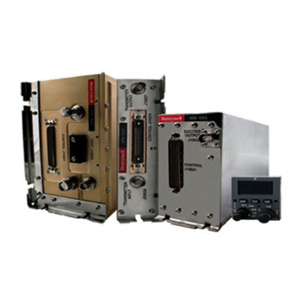
KHF 1050 SYSTEM INSTALLATION MANUAL DESCRIPTION AND OPERATION 1. System Description A basic KHF 1050 HF Communication System (also known as a Primus HF 1050) consists of three individual units: KAC 1052 Antenna Coupler, KPA 1052 Power Amplifier, and KRX 1053 Receiver/Exciter (refer to “Figure 1 - Typical System”... -
Page 28: Apr/2006
KHF 1050 SYSTEM INSTALLATION MANUAL Figure 2 - PS440 Control Display Unit Figure 3 - MC-850 Multifunction Control and Display Unit (MCDU) Page 2 23-10-09 Revison 2 Apr/2006... -
Page 29: Apr/2006
KHF 1050 SYSTEM INSTALLATION MANUAL Figure 4 - RM-855 Radio Management Unit NOTE: The KHF 1050 can also be controlled by other Honeywell EPIC systems, such as the EASy System. Consult the respective system manuals for more information. Page 3... -
Page 30: Apr/2006
Coupler to the KRX 1053 Receiver/Exciter via the KPA 1052. The KHF 1050 can be installed as a single or dual HF system. A configuration is called a “dual system” when two KHF 1050 HF systems are installed in the same aircraft to share one antenna. -
Page 31: Apr/2006
AND HF2. IT IS RECOMMENDED THAT HF1 CABLES BE COLOR CODED RED AND HF2 CABLES BE COLOR CODED GREEN. Several operating mode options are available for the KHF 1050 HF system to meet particular operational needs. USB Voice (upper sideband A3J) and AME (amplitude modulation equivalent A3H) are standard modes of operation that should be enabled on all system configurations. -
Page 32: Apr/2006
KHF 1050 SYSTEM INSTALLATION MANUAL Figure 5 - Typical System Block Diagram Page 6 23-10-09 Revison 2 Apr/2006... -
Page 33: Apr/2006
KHF 1050 SYSTEM INSTALLATION MANUAL 1.B. System Component Descriptions The required and optional equipment of a KHF 1050 HF Communication System is listed below: KAC 1052 Antenna Coupler (required) KPA 1052 Power Amplifier (required) KRX 1053 Receiver/Exciter (required) Compatible HF Control Display Unit (required) Mounting Tray for the KAC1052, KPA1052 and KRX1053 (required) 1.B.(1) -
Page 34: Apr/2006
The RM-855 displays basic frequency and mode information. Via the ARINC 429 bus it provides frequency, channel, transmitter power and squelch level selection. The RM-855 does not support some of the features of the KHF 1050. Refer to “Table 1 - Honeywell Controller Features”... - Page 35 KHF 1050 SYSTEM INSTALLATION MANUAL FEATURE PS440 RM855 EPIC MCDU User Programmable Channels Emergency Channels Total User Programmable Fixed ITU Channels Tuning Step Size (Hz) 1000 Squelch Types Clarifier Function Coupler Tune Status Indication Aural Tone Tone Tone Visual Annunc.
-
Page 36: Apr/2006
KHF 1050 SYSTEM INSTALLATION MANUAL 1.C. Component Installation Kits 1.C.(1) KAC 1052 Antenna Coupler Installation Kits NOTE: The KAC 1052 is certified for vertical installation in fixed wing aircraft only. Helicopter applications must use a horizontal mount KAC 1052 tray, 071-00202-0001, supplied in the 050-03699-0000/0001 kits. -
Page 37: Apr/2006
KHF 1050 SYSTEM INSTALLATION MANUAL Part Number Description UM Qty 030-00005-0000 CONN BNC UG 88C/U 030-01157-0011 SOCKET CRMP 20G 030-03517-0004 CONN, D-SUB, RECPT, CRIMP, HOOD, 37 POS 047-06261-0036 CNDCT STRIP 36 INCH 047-12728-0001 KAC 1052 STRAP 071-00202-0000 HORIZ TRAY ASSEMBLY, KAC 1052... - Page 38 KHF 1050 SYSTEM INSTALLATION MANUAL Part Number Description UM Qty 030-00005-0000 CONN BNC UG 88C/U 030-01157-0011 SOCKET CRMP 20G 030-03517-0004 CONN, D-SUB, RECPT, CRIMP, HOOD, 37 POS 047-06261-0036 CNDCT STRIP 36 INCH 071-00200-0000 VERT TRAY ASSEMBLY KAC 1052 Table 8 - KAC 1052 Dual Vertical Installation Kit...
-
Page 39: Apr/2006
KHF 1050 SYSTEM INSTALLATION MANUAL 1.C.(2) KPA 1052 Power Amplifier Installation Kits Part Number Description UM Qty 030-00005-0000 CONN BNC UG 88C/U 030-01157-0011 SOCKET CRMP 20G 030-01466-0002 CONT, COMBO-D, 40A, PWR, 8 AWG, CRMP BAR 030-01497-0001 CONN, D-SUB, CABLE CLAMP FOR METAL HOOD EA... - Page 40 KHF 1050 SYSTEM INSTALLATION MANUAL Part Number Description UM Qty 030-00005-0000 CONN BNC UG 88C/U 030-01157-0011 SOCKET CRMP 20G 030-03517-0004 CONN, D-SUB, RECPT, CRIMP, HOOD, 37 POS 047-06261-0036 CNDCT STRIP 36 INCH 071-00202-0001 HELICOPTER TRAY ASSEMBLY, KAC 1052 Table 14 - KAC 1052 Helicopter Installation Kit...
-
Page 41: Apr/2006
KHF 1050 SYSTEM INSTALLATION MANUAL 1.C.(3) KRX 1053 Receiver/Exciter Installation Kits Part Number Description 030-00005-0000 CONN BNC UG 88C/U 030-01451-0000 CONTACT, SOCKET, SIZE 22, 50 U-IN AU 030-03518-0001 CONN D-SUB RCPT HI-DENS W/HOOD 104 POS 071-00184-0000 TRAY ASSEMBLY Table 17 - KRX 1053 Installation Kit... -
Page 42: Equipment Required But Not Supplied
KHF 1050 SYSTEM INSTALLATION MANUAL Part Number Description UM Qty 071-01214-0001 GRND HF ANT KIT Table 21 - Long-Wire Antenna Installation Kit (P/N: 071-01214-0002) NOTE: All units, accessories and parts contained in Antenna Installation Kit P/N 071-01214-0002 have Part Manufacturer Approval (PMA) by the manufacturer. -
Page 43: Apr/2006
KHF 1050 SYSTEM INSTALLATION MANUAL Equipment Required But Not Supplied AIRCRAFT EQUIPMENT DESCRIPTION 16 AWG Single conductor P/N 025-00091-0004 10 AWG Single conductor P/N 025-00091-0007 8 AWG Single conductor P/N 025-00091-0008 24 AWG Single conductor with shield and jacket P/N... -
Page 44: Apr/2006
KHF 1050 SYSTEM INSTALLATION MANUAL Equipment Required But Not Supplied AIRCRAFT EQUIPMENT DESCRIPTION AN-14 3,830 Nominal Circular Mil Area 0.150 inches Max. Overall Diameter 2.99 ohms Max. per 1000 feet @ 20°C 32 amps Max. Cont. Current Rating** 17 amps Max. Cont. Current Rating***... - Page 45 WARNING: THE HIGH VOLTAGE HN CABLES ARE SPECIFICALLY DESIGNED TO WITHSTAND THE HIGH RF VOLTAGE GENERATED BY THE KHF 1050 SYSTEM. THEY CAN NOT BE REPLACED BY CABLES THAT HAVE NOT BEEN TESTED TO THESE HIGH VOLTAGES AT ALTITUDE. THESE CABLES...
-
Page 46: Apr/2006
KHF 1050 SYSTEM INSTALLATION MANUAL NOTE: XX = length in inches Figure 6 - High Voltage Single Coupler Cable Assemblies Page 20 23-10-09 Revison 2 Apr/2006... -
Page 47: Apr/2006
KHF 1050 SYSTEM INSTALLATION MANUAL Figure 7 - Coupler Cable Typical Connector Dimensions Figure 8 - High Voltage Dual Coupler Cables P/N 155-03020-XXXX through 155-03024-XXXX (Sheet 1 of 3) Page 21 23-10-09 Revison 2 Apr/2006... -
Page 48: Apr/2006
KHF 1050 SYSTEM INSTALLATION MANUAL Figure 8 - High Voltage Dual Coupler Cables P/N 155-03025-XXXX through 155-03029-XXXX (Sheet 2 of 3) Page 22 23-10-09 Revison 2 Apr/2006... -
Page 49: Apr/2006
KHF 1050 SYSTEM INSTALLATION MANUAL Figure 8 - High Voltage Dual Coupler Cables Cable Series Matrix Table (Sheet 3 of 3) 1.E. Optional (non-essential) Aircraft Equipment Not applicable. Page 23 23-10-09 Revison 2 Apr/2006... -
Page 50: Apr/2006
Table 23 - Related Publications 2. Component Configurations System component configurations are listed in this section. The overall configuration of a KHF 1050 HF system is dependent on the component versions installed in the aircraft. 2.A. KAC 1052 Antenna Coupler Configurations... -
Page 51: Krx 1053 Receiver/Exciter Configurations
KHF 1050 SYSTEM INSTALLATION MANUAL 2.C. KRX 1053 Receiver/Exciter Configurations PART NUMBER VERSION DESCRIPTION 064-01073 -0101 Receiver/Exciter - standard 064-01073 -5101 Receiver/Exciter - customer specific Table 26 - KRX 1053 Configurations 2.D. PS440 Control Display Unit Configurations DISPLAY HONEYWELL P/N VERSION MFG. -
Page 52: Rm-855 Radio Management Unit Configurations
3.A. General Specifications The KHF 1050 HF System is a solid state design with 200 watts PEP of output power, supplied by 28 VDC, with an operational frequency range of 2.0 to 29.9999 MHz with 100 Hz resolution. The KHF 1050 HF System has been type accepted by the FCC and TSO approved. -
Page 53: 2) 23 Mhz Limit Mode
3.B.(2) 23 MHz Limit Mode The KHF 1050 HF system can be strapped to limit the frequency of operation to an upper limit of 22.9999 MHz for certification in countries that may require such an upper frequency limit. If using a PS440 controller, both the KRX 1053 and the PS440 must be strapped for the 23 MHz limit. -
Page 54: Apr/2006
KHF 1050 SYSTEM INSTALLATION MANUAL 3.B.(3) Channel Mode When operating in the channel mode the KHF 1050 HF system can operate as a simplex or semi-duplex communication system. Transmit and receive frequencies are selected by selecting a pre-programmed channel. The KHF 1050 supports three types of channel mode operation: •... -
Page 55: Apr/2006
Regardless of the operating mode selected by the pilot, the SELCAL AUDIO OUTPUT is derived from an AM receiver inside the KRX 1053. 3.C. Component Leading Particulars Leading particulars for components of the KHF 1050 HF system are listed below. 3.C.(1) KAC 1052 Antenna Coupler, Leading Particulars CHARACTERISTIC... - Page 56 KHF 1050 SYSTEM INSTALLATION MANUAL CHARACTERISTIC DESCRIPTION Antenna Matching Capability: Wire Antenna: 10 to 25 feet grounded (55,000 feet maximum altitude). 25 to 30 feet may be grounded or ungrounded. If ungrounded, 30,000 feet max altitude. 30 to 75 feet ungrounded (30,000 feet maximum altitude)
-
Page 57: 2) Kpa 1052 Power Amplifier, Leading Particulars
KHF 1050 SYSTEM INSTALLATION MANUAL 3.C.(2) KPA 1052 Power Amplifier, Leading Particulars CHARACTERISTIC DESCRIPTION Weight: Refer to “Figure 2027 - KPA 1052 Power Amplifier Outline and Mounting” Dimensions: Refer to “Figure 2027 - KPA 1052 Power Amplifier Outline and Mounting”... - Page 58 KHF 1050 SYSTEM INSTALLATION MANUAL CHARACTERISTIC DESCRIPTION Third Order -28 dB relative to mean power output Intermodulation -31 dB relative to PEP output Distortion: Carrier and Noise Level J3E with 2 KHz Audio Modulation: Not greater than 5% of 50 watts PEP...
-
Page 59: 3) Krx 1053 Receiver/Exciter, Leading Particulars
KHF 1050 SYSTEM INSTALLATION MANUAL 3.C.(3) KRX 1053 Receiver/Exciter, Leading Particulars CHARACTERISTIC DESCRIPTION WEIGHT: Refer to “Figure 2028 - KRX 1053 Receiver/Exciter Outline and Mounting” OVERALL DIMENSIONS: Refer to “Figure 2028 - KRX 1053 Receiver/Exciter Outline and Mounting” TEMPERATURE RANGE Operating: -55°C to +70°C... - Page 60 KHF 1050 SYSTEM INSTALLATION MANUAL CHARACTERISTIC DESCRIPTION SSB and AME: 10 dB (max) change in audio level with RF level changes between 10 uV and 100,000 uV Distortion SSB: 5% (max) Receiver Intermodulation: 25 dB (min) below the desired tone <...
- Page 61 Product Support (913-712-0600) regarding specific frequencies of interest. 3) The KHF 1050 system is FCC certified under Parts 87 and 90 for J2D, J3D, H2D and H3 modes of data operation; and under Parts 80, 87, and 90 for J3E, H3E and R3E modes of voice operation.
-
Page 62: 4) Ps440 Control Display Unit, Leading Particulars
KHF 1050 SYSTEM INSTALLATION MANUAL Table 33 - KRX 1053 Leading Particulars 3.C.(4) PS440 Control Display Unit, Leading Particulars CHARACTERISTIC DESCRIPTION Unit Dimensions: Refer to “Figure 2020 - PS440 Control Display Unit Outline and Mounting” Weight: 1.2 lbs (0.707 Kg) maximum... -
Page 63: System Function
KRX 1053 Receiver/Exciter • Compatible Control Display Unit (CDU) The basic KHF 1050 HF system is a mobile communication system for aircraft. It operates in a frequency range between 2.0 and 29.9999 MHz offering several different emission modes to provide voice communication. -
Page 64: Apr/2006
Some installations may be configured to turn the KHF 1050 system “ON” whenever the Avionics Master switch is turned “ON”. However, it is preferable to provide a means of applying power to the KHF 1050 system so that the system can be turned “OFF” on flights when HF communications is not required. -
Page 65: Component Functions
KHF 1050 SYSTEM INSTALLATION MANUAL 5. Component Functions 5.A. PS440 CDU Function Refer to Pilots Guide P/N 006-18289-0000 for PS440 Control Display Unit operation. 5.B. MC-850 MCDU Function Refer to Users Guide P/N PS7032270 for MC-850 MCDU operation. 5.C. RM-855 RMU Function Refer to Pilots Guide P/N A48-1146-121 for RM-855 RMU operation. -
Page 66: Apr/2006
KHF 1050 SYSTEM INSTALLATION MANUAL Blank Page Page 40 23-10-09 Revison 2 Apr/2006... -
Page 67: Apr/2006
Intermittent or improperly connected cables or connectors. • Defective units. • Poorly regulated aircraft DC power. • Poor grounding of KHF 1050 HF system or poor aircraft bonding. • Audio ground loops. • RF interference. CAUTION: POWER CARTS MAY REGULATE POORLY WHEN SUBJECTED TO STRONG RF FIELDS. -
Page 68: Apr/2006
KHF 1050 SYSTEM INSTALLATION MANUAL 2.A. Preliminary Check 1. Prior to turning the system ON, ensure that all connectors are properly seated in their proper location. 2. Turn the system ON. As the system turns ON it performs a brief self-test. -
Page 69: Apr/2006
KHF 1050 SYSTEM INSTALLATION MANUAL FUNCTION TURN ON PILOT CONT Discrete Line and Flash Checksum DSP ROM and RAM Internal Clocks RF Board XMT Operation RF Board RCV Operation DC Voltages Rx/Ex Internal Temperature PA and ACP Operation Rx/Ex - CPLR Serial Communication... -
Page 70: Apr/2006
These maintenance observations are stored in non-volatile memory within the KHF 1050 system so they can be retrieved with appropriate test equipment. If the maintenance observation is serious enough to indicate Antenna Coupler failure, the failure shall be communicated to the receiver/exciter for reporting to the HF controller. -
Page 71: Apr/2006
KHF 1050 SYSTEM INSTALLATION MANUAL 7. In the event that a problem is detected during either the turn-on test or the pilot-activated self-test, an error message will appear on the controller. The error message may indicate a failure of one or more of the following: •... -
Page 72: Apr/2006
KHF 1050 SYSTEM INSTALLATION MANUAL 2.C. Antenna Coupler Tune Fault The antenna coupler must tune the antenna prior to being able to make a transmission. Keying the microphone on a previously untuned channel initiates a tune sequence that can last up to 30 seconds. (If the channel has been previously tuned, the retune time typically takes less that 50 msec.) In the event the antenna... -
Page 73: Apr/2006
These stations transmit in the AM mode. However, they can be received by the KHF 1050 System in the USB Voice (UV), LSB Voice (LV), AM or Reduce-Carrier (RC) modes. -
Page 74: Apr/2006
KHF 1050 SYSTEM INSTALLATION MANUAL 3. Upon completion of the tune cycle, the tune indication will disappear and the display will return to a normal receive window. The receiver audio will likely be different than it was prior to tuning the antenna and it may be necessary to readjust the squelch if there is significant noise on the channel. -
Page 75: Apr/2006
If unit fails to tune the antenna after 3 attempts, select a different frequency and try to retune the antenna at the new frequency. Turn the KHF 1050 system off and check the coaxial cable connections between the KAC 1052 and the antenna feedpoint. - Page 76 4. Bench Test Harness Considerations The following kits and components are recommended for assembling a Bench-Test Harness for the KHF 1050 System. Commonly available connectors, such as BNC jacks, microphone jacks and banana or pin jacks can be purchased from local electronic component suppliers.
-
Page 77: Apr/2006
NOTE 1: For use with a PS440 Controller. For other types of controllers, substitute appropriate connectors. NOTE 2: To operate with the KHF 1050 Maintenance Program, connections must be made between a personal computer and the KAC 1052 or KRX 1053. For interfacing a personal computer to the KRX 1053,... -
Page 78: Apr/2006
KHF 1050 SYSTEM INSTALLATION MANUAL Blank Page Page 1012 23-10-09 Revison 2 Apr/2006... - Page 79 KHF 1050 SYSTEM INSTALLATION MANUAL Figure 1001 - KHF 1050 System Bench Test Harness Page 1013/1014 23-10-09 Revison 2 Apr/2006...
- Page 80 Blank Page...
- Page 81 KHF 1050 SYSTEM INSTALLATION MANUAL Figure 1002 - PC Data Cable Connections Page 1015/1016 23-10-09 Revison 2 Apr/2006...
- Page 82 Blank Page...
- Page 83 Consult the appropriate unit Maintenance/Overhaul Manual for complete performance test information. The only exception to the “on condition maintenance” statement for the KHF 1050 System is the KAC 1052 pressurization check described in Paragraph “10.A.(2)
- Page 84 Interconnect diagrams at the end of this section show the interconnection of various system components. The KHF 1050 HF system should be installed in the aircraft in a manner consistent with acceptable workmanship and engineering practices and according to instructions set forth in this publication.
- Page 85 24 inches, including the connector length. Lengths in excess of 24 inches can create significant operational difficulties. NOTE: Due to the high level of RF voltage the KHF 1050 system is capable of generating, only a specially fabricated Honeywell feedline may be used.
- Page 86 Lesser separation is acceptable in an aircraft where a metal skin shields the occupants from the antenna. The antenna is a primary factor for maximum performance of the KHF 1050 HF system. While numerous options are available in the choice of antenna configurations, some configurations are better suited for a particular installation than others.
-
Page 87: Apr/2006
KHF 1050 SYSTEM INSTALLATION MANUAL Commonly used aircraft HF antennas will generally fall into one of four categories: • "V" (Referring to the V shape formed by the antenna wire) and Long wire antenna. • Short grounded wire antenna. •... -
Page 88: Apr/2006
KHF 1050 SYSTEM INSTALLATION MANUAL 5.B.(5)(b) Wing Tip “V” Antenna Mounting Location (refer to “Figure 2001 - Typical Wing Tip “V” Antenna” The wing type “V” is one of the most effective HF antennas which can be utilized on an aircraft. It is well suited for slow and moderate speed aircraft which require optimum HF communication and performance. -
Page 89: Apr/2006
KHF 1050 SYSTEM INSTALLATION MANUAL 5.B.(5)(c) Inverted “V” Antenna Mounting Location (refer to “Figure 2002 - Typical Inverted “V” Antenna” The inverted “V” antenna is recommended when a wing “V” is not practical and the antenna coupler is to be mounted in the aft position of the aircraft. -
Page 90: Apr/2006
KHF 1050 SYSTEM INSTALLATION MANUAL 5.B.(5)(d) Long Wire Antenna Mounting Location (refer to “Figure 2003 - Typical Long Wire Antenna” The long wire antenna is used when the KAC 1052 Antenna Coupler is located in the forward part of the aircraft. It will provide maximum signal radiation off the sides of the aircraft. -
Page 91: Apr/2006
KHF 1050 SYSTEM INSTALLATION MANUAL 5.B.(5)(f) Short Wire to Vertical Stabilizer Antenna Mounting Location (refer to “Figure 2004 - Typical Short Wire to Vertical Stabilizer Antenna” The most common form of short grounded wire antennas have the feedthru insulator mounted on the upper aft part of the fuselage, as far forward of the vertical stabilizer as is practical. -
Page 92: Apr/2006
KHF 1050 SYSTEM INSTALLATION MANUAL Figure 2005 - Typical Short Wire to Wing Antenna Figure 2006 - Typical Short Wire to Horizontal Stabilizer Antenna Page 2010 23-10-09 Revison 2 Apr/2006... -
Page 93: Apr/2006
KHF 1050 SYSTEM INSTALLATION MANUAL 5.B.(5)(h) Shunt Antenna Mounting Location Two types of shunt antennas are commonly used. The most preferable type, on a fixed wing aircraft, is designed by the airframe manufacturer as a part of the airframe structure. It is most often an electrically isolated section of the leading edge of the vertical stabilizer, grounded at the top. -
Page 94: Apr/2006
KHF 1050 SYSTEM INSTALLATION MANUAL 5.B.(5)(j) Shorted Tranline or Towel Bar Antenna Mounting Location (refer to “Figure 2008 - Typical Shorted Tranline or Towel Bar Antenna” Grounded transline (transmission line), often referred to as “towel bar” antennas because their shape resembles a towel bar, are best suited for helicopter applications. -
Page 95: Apr/2006
5.C. Interwiring and Cable Fabrication 5.C.(1) Fabrication and Routing “Figure 2029 - KHF 1050 HF System Interconnect” provides a KHF 1050 HF Communication System interconnect summary. Cabling must be fabricated according to the interwiring diagrams. The length of the wires to parallel pins should be approximately the same length, for best current distribution. -
Page 96: Apr/2006
5.C.(3) Primary Power and Circuit Breaker Requirements All units in the KHF 1050 system should be protected by circuit breakers in the positive primary power lines. The KPA 1052 should use an individually dedicated 30 amp slow-acting circuit breaker. The KAC 1052 and KRX 1053 can share a common 5 amp circuit breaker, or be individually protected by a 5 amp circuit breaker for the KAC 1052 and a 2 amp circuit for the KRX 1053. -
Page 97: Apr/2006
The cable connecting the KAC 1052 antenna output (J10528) to the antenna or antenna feed-through must be a specially fabricated feedline supplied by Honeywell. Due to the high level of RF voltage the KHF 1050 system is capable of generating, substitute cables must not be used. Refer to Paragraph “1.D. -
Page 98: Apr/2006
Controller, the overbraid should be grounded only at the KRX 1053 end. 5.C.(8) Connectors Mating connectors for the KHF 1050 HF system components are identified on the appropriate outline drawing. Associated connector installation kits are specified in the “DESCRIPTION AND OPERATION”... - Page 99 KHF 1050 SYSTEM INSTALLATION MANUAL 5.C.(7)(a) KAC 1052 Antenna Coupler Connector Figure 2009 - KAC 1052 Antenna Coupler Connector (J10521) Pin Configuration KAC 1052 CONNECTOR PIN DEFINITIONS SIGNAL NAME DESCRIPTION PRI PWR RTN PRIMARY POWER RETURN PWR CONT RTN POWER ON/OFF CONTROL RETURN...
- Page 100 KHF 1050 SYSTEM INSTALLATION MANUAL KAC 1052 CONNECTOR PIN DEFINITIONS SIGNAL NAME DESCRIPTION PWR CONT POWER ON/OFF CONTROL STRP B STRAP B SPARE CPLR TXD BUS - PHOTO-COUPLER COMMON SOURCE EXCTR COM EXCTR COMMON MATCH ON - MATCHING CIRCUIT ON -...
- Page 101 KHF 1050 SYSTEM INSTALLATION MANUAL 5.C.(7)(b) KPA 1052 Power Amplifier Connector Figure 2010 - KPA 1052 Power Amplifier Connector (J10524) Pin Configuration KPA 1052 CONNECTOR PIN DEFINITIONS SIGNAL NAME DESCRIPTION +27.5V PRI PWR +27.5 VDC PRIMARY POWER PRI PWR RTN...
- Page 102 KHF 1050 SYSTEM INSTALLATION MANUAL KPA 1052 CONNECTOR PIN DEFINITIONS SIGNAL NAME DESCRIPTION CP COM PHOTO-COUPLER COMMON SOURCE PA SCK PA SERIAL CLOCK PA INHB+ PA INHIBITION + PA ALM + #2 PA ALARM + #2 PC COM PHOTO-COUPLER COMMON...
- Page 103 KHF 1050 SYSTEM INSTALLATION MANUAL 5.C.(7)(c) KRX 1053 Receiver/Exciter Connector Figure 2011 - KRX 1053 Receiver/Exciter Connector (J10531) Pin Configuration KRX 1053 CONNECTOR PIN DEFINITIONS SIGNAL NAME DESCRIPTION PWR CONT RTN POWER ON/OFF CONTROL RETURN A615 DATA LDR INP#2(A) (not used)
- Page 104 KHF 1050 SYSTEM INSTALLATION MANUAL KRX 1053 CONNECTOR PIN DEFINITIONS SIGNAL NAME DESCRIPTION AGC TEST AGC TEST SELCAL AUD H SELCAL AUDIO HIGH EXT MODEM AUD H EXTERNAL MODEM AUDIO HIGH MIC AUD H MIC AUDIO HIGH +27.5V PRI PWR +27.5 VDC PRIMARY POWER...
- Page 105 KHF 1050 SYSTEM INSTALLATION MANUAL KRX 1053 CONNECTOR PIN DEFINITIONS SIGNAL NAME DESCRIPTION +27.5V PRI PWR +27.4 VDC PRIMARY POWER SPARE (not used) SPARE (not used) SPARE (not used) SPARE (not used) SPARE (not used) OTHER SIDE ON OTHER SIDE ON SENSE...
- Page 106 KHF 1050 SYSTEM INSTALLATION MANUAL KRX 1053 CONNECTOR PIN DEFINITIONS SIGNAL NAME DESCRIPTION DATA BUS SHLD GND GND DATA BUS SHIELD GND DATA BUS SHLD GND GND DATA BUS SHIELD GND HF TUNE/M STAT(B) HF TUNING/MODE STATUS (B) DATA BUS SHLD GND...
- Page 107 KHF 1050 SYSTEM INSTALLATION MANUAL KRX 1053 CONNECTOR PIN DEFINITIONS SIGNAL NAME DESCRIPTION DATA BUS SHLD GND GND DATA BUS SHIELD GND BUS COM GND BUS COMMON GND GND EXCTR COM GND EXCITER COMMON L SIDE LEFT SIDE GND DISCRETE SIGNAL GROUND...
-
Page 108: Apr/2006
KHF 1050 SYSTEM INSTALLATION MANUAL 5.C.(7)(d) PS440 Control Display Unit Connector Figure 2012 - PS440 Control Display Unit Connector (J1) Pin Configuration PS440 CONNECTOR PIN DEFINITIONS FUNCTION 28 VDC In DC Ground Chassis Ground Spare Reserved Spare Spare Spare Spare... -
Page 109: Apr/2006
KHF 1050 SYSTEM INSTALLATION MANUAL PS440 CONNECTOR PIN DEFINITIONS FUNCTION Spare HF On/Off Out Spare ARINC 429 Out A Spare Reserved 28 VDC Dimming Bus ARINC 429 In #1A Test Out Reserved Spare Spare Spare Spare Spare Spare Spare Spare... -
Page 110: Apr/2006
KHF 1050 SYSTEM INSTALLATION MANUAL PS440 CONNECTOR PIN DEFINITIONS FUNCTION ARINC 429 In #1B Spare Spare Spare Spare Spare HFDL Inhibit In SDI Config In Reduced Carrier Inhibit In 0.1 KHz Enable In Spare Out #1 Spare 5 VDC / AC Lighting High... - Page 111 KHF 1050 SYSTEM INSTALLATION MANUAL 5.C.(7)(e) MC-850 MCDU Connectors For MC-850 MCDU connection information, refer to MC-850 installation documentation pertinent to each specific application. 5.C.(7)(f) RM-855 RMU Connector Figure 2013 - RM-855 RMU Connector (144J1) Pin Configuration RM-855 CONNECTOR PIN DEFINITIONS...
-
Page 112: Apr/2006
KHF 1050 SYSTEM INSTALLATION MANUAL 5.C.(7)(g) BNC Connector Assembly (P/N 030-00005-0001) Figure 2014 - BNC Connector Assembly Procedure Page 2030 23-10-09 Revison 2 Apr/2006... -
Page 113: Apr/2006
KHF 1050 SYSTEM INSTALLATION MANUAL 5.C.(9) Connector Pin Tools The crimping tools, associated positioners, insertion tools and extraction tools used during the fabrication of cables are identified in “Figure 2015 - Crimping and Insertion/Extraction Tools” “Figure 2016 - Crimping and Insertion/Extraction Tools”... -
Page 114: Apr/2006
KHF 1050 SYSTEM INSTALLATION MANUAL Figure 2016 - Crimping and Insertion/Extraction Tools Page 2032 23-10-09 Revison 2 Apr/2006... -
Page 115: Apr/2006
Strapping Options 5.D.(1) KRX 1053 Receiver/Exciter Strapping Options NOTE: Asserted = GND, Not Asserted = OPEN Refer to “Figure 2029 - KHF 1050 HF System Interconnect” for KRX 1053 strapping options. 5.D.(1)(a) Power ON/OFF Control - (J10531-23) PWR CONT An external controller turns on the KRX 1053 Receiver/Exciter by asserting (grounding) the POWER ON/OFF CONTROL discrete input. -
Page 116: Apr/2006
KHF 1050 SYSTEM INSTALLATION MANUAL When the BURST/CONTINUOUS TUNING MODE discrete input is asserted, the KRX 1053 Receiver/Exciter operates by receiving bursts of ARINC 429 tuning data. In a system consisting of two external HF controllers, with one controller connected to HF CONTROLLER INPUT #1 data bus and the other... -
Page 117: Apr/2006
KHF 1050 SYSTEM INSTALLATION MANUAL • The KRX 1053 Receiver/Exciter sets the SDI field of all ARINC 429 transmitted messages to 00B, and it sets bits 30 and 31 (status field) of all messages except that with label 351 to 11B, indicating an invalid condition shall set bits 30 and 31 (status field) of the label 351 Maintenance Status message to 00B, indicating a fault condition. -
Page 118: Apr/2006
Accessing this adjustment requires removing the dust cover. Finally, the transmitter sidetone level can be adjusted with respect to the receiver audio by use of the KHF 1050 Maintenance Program software (PN 222-30144-0000). Changing the sidetone level also changes the level of the antenna coupler tune tone, if activated. -
Page 119: Apr/2006
Maintenance Test- (J10531-78) MAINT TEST When the MAINTENANCE TEST discrete input is asserted (grounded), the KRX 1053 Receiver/Exciter RS-232 Maintenance port accepts test commands from the KHF 1050 Maintenance Program (P/N 222-31044-0000). This input is continuously read. Page 2037 23-10-09... -
Page 120: Apr/2006
KHF 1050 SYSTEM INSTALLATION MANUAL 5.F.(3) External Data Keyline HI (J10531-38) EXT DATA KEYLINE H When the external resistance between the EXTERNAL DATA KEYLINE HI and LO pins is ten ohms or less, the KRX 1053 Receiver/Exciter activates the transmitter and uses the audio at the EXTERNAL MODEM AUDIO INPUT as the modulation source. -
Page 121: Apr/2006
KHF 1050 SYSTEM INSTALLATION MANUAL When asserted (grounded), bit 18 of message (Output label 037), word ID #1 “Other side keyed” is set to 0. The OTHER SIDE PTT and the KEY EVENT discrete inputs/outputs function as an “interlock” to ensure that both systems can not transmit at the same time. -
Page 122: Apr/2006
The bonding strap should be made of a solid conductive material rather than braid. Strap thickness should be 0.010 inches or greater. A one inch wide silver plated copper strap, available from Honeywell, is recommended. P/N 047-06261-0036 is a 36 inch length of the strap. This strap can be cut to length and punched as necessary. - Page 123 KHF 1050 SYSTEM INSTALLATION MANUAL 6.B. KAC 1052 Antenna Coupler Installation 6.B.(1) General Select a mounting location for the KAC 1052 Antenna Coupler, referring to Paragraph “5.B.(1) KAC 1052 Antenna Coupler Mounting Location” 6.B.(2) Power Requirements The KAC 1052 Antenna Coupler will operate from a 28 Vdc power supply. The unit must be connected to the aircraft power supply with a circuit breaker with not less than 5 Amp rating.
- Page 124 KHF 1050 SYSTEM INSTALLATION MANUAL • Place the KAC 1052 Antenna Coupler unit into the mounting tray and secure it in place with two knobs. Provisions for safety wire installation is provided. Safety wire must be installed on fixed-wing trays. However, safety wire is optional for the helicopter mounting trays.
- Page 125 KHF 1050 SYSTEM INSTALLATION MANUAL 6.E. PS440 (or other compatible) CDU Installation 6.E.(1) Perform the installation procedures as follows: 6.E.(1)(a) Select the desired location for the control panel. 6.E.(1)(b) Make the appropriate cutout (if necessary), Refer to “Figure 2020 - PS440 Control Display Unit Outline and Mounting”...
- Page 126 KHF 1050 SYSTEM INSTALLATION MANUAL The unit is designed with fully adjustable dim settings for the display backlighting, panel lighting and annunciator lighting. It is shipped from the factory with standard adjustments, which should be satisfactory for most installations. To change these settings from the factory presets, the following procedure should be followed.
-
Page 127: Apr/2006
Good electrical bonding of all antenna connections is required. Particularly important is the bonding of the far end of the antenna in a grounded-antenna configuration. If using the KHF 1050 Antenna Kit (P/N -71-01214-0002), the ground plate associated with the 25ARM300-20E 30 feed-through termination must be well bonded to the fuselage. - Page 128 KHF 1050 SYSTEM INSTALLATION MANUAL 6.F.(3) HF Antenna Kit Figure 2017 - HF Antenna Kit PN 071-01214-0002 (1) Vertical Fin Anchor Kit (4) Feed-Through Insulator (2) Vertical Fin “V” Tension Unit (7) Feed-Through Assembly (3) Anti-Precipitation Antenna Wire (8) HN RF Cable Assembly...
- Page 129 System Checkout 7.B.(1) General The KHF 1050 HF Communication System requires three stages of post-installation testing to ensure proper operation: (1) A system interwiring check is performed before installation of system components and before power is applied, to verify that all aircraft and HF system interconnections are correct.
- Page 130 KHF 1050 SYSTEM INSTALLATION MANUAL 7.B.(2)(b) Check that all functions are properly strapped to reflect the aircraft system configuration Paragraph “5.D. Strapping Options” 7.B.(2)(c) Double-check continuity of all power pins. 7.B.(3) Visual Inspection Perform the visual inspection/check procedure (“Table 2007 - Visual Inspection Procedure”...
- Page 131 KHF 1050 SYSTEM INSTALLATION MANUAL 7.C. Flight Test While in flight, establish communications with another HF station. It is important that the frequencies selected be appropriate for the distance between the aircraft and the other station (see “Table 2008 - Typical HF Signal Propagation Distance”...
- Page 132 KHF 1050 SYSTEM INSTALLATION MANUAL 7.D. SWR and Power Measurement Procedures The following information is provided as an aid, in the event transmitter problems are encountered during post-installation testing. A SWR/wattmeter can be connected between the KPA 1052 Output (J10527) and the KAC 1052 Input (J10523) to check the RF output power and to verify the Antenna Coupler is finding a good tune.
- Page 133 KHF 1050 SYSTEM INSTALLATION MANUAL 8. Removal and Re-installation CAUTION: REMOVE ALL POWER BEFORE PERFORMING REMOVAL AND RE-INSTALLATION PROCEDURES. 8.A. KAC 1052 Antenna Coupler Removal and Re-installation 8.A.(1) KAC 1052 Antenna Coupler Removal • Detach cables from connector J10521. •...
- Page 134 KHF 1050 SYSTEM INSTALLATION MANUAL 8.C. KRX 1053 Receiver/Exciter Removal and Re-installation 8.C.(1) KRX 1053 Receiver/Exciter Removal • Detach cables from connector J10531. • Detach the coaxial cable from J10532. • Loosen retaining screw clamp located at the front of the KRX 1053 Receiver/Exciter.
- Page 135 9.B. System Protection The KHF 1050 system is primarily protected by circuit breakers located at the circuit breaker panel in the aircraft. The KPA 1052 and KRX 1053 contain internal fuses for additional protection.
- Page 136 KHF 1050 SYSTEM INSTALLATION MANUAL NOTE: Limit cleaning of equipment interiors to that required at bench overhaul. 10. System Maintenance Programs 10.A. System Maintenance Recommendations 10.A.(1) General Perform a system performance check when a component of the system is replaced or installed.
- Page 137 PS440 controller "PRS W" appears on the display when bit 15 is set (and bit 28 is zero). During the Coupler Pressure Warning the KHF 1050 system will continue to operate normally. A Pressure Warning indicates that the antenna coupler may be approaching a Pressure Fault condition.
- Page 138 KHF 1050 SYSTEM INSTALLATION MANUAL 10.B. Field Alignment “Figure 2019 - KRX 1053 Adjustments” identifies various adjustment locations and factory settings for the KRX 1053 Receiver/Exciter. Figure 2019 - KRX 1053 Adjustments Page 2056 23-10-09 Revison 2 Apr/2006...
- Page 139 . To utilize these setup parameters, the PC must be connected to the KRX 1053. 10.C.(3) BITE Information The maintenance data collection features of the KHF 1050 System include the following three types of Built In Test (BITE) monitoring: •...
- Page 140 USB ports if using a USB-Serial adapter. The default port is Com 1. The RS-232 parameters are fixed by the program so as to be compatible with the KHF 1050 system. Page 2058...
- Page 141 KHF 1050 SYSTEM INSTALLATION MANUAL 10.C.(6) Installation Setup (RX/EX Defaults Setup Variables) The installer has the ability to adjust the following four parameters via the Maintenance Program by accessing the using the RX/EX Maintenance page. To make adjustments, click on Read Defaults to determine the present default settings.
- Page 142 -30 dB Table 2009 - Sidetone Audio Levels Squelch Type: The KHF 1050 System offers four types of squelch. If using a controller that does not allow for the selection of the squelch type (i.e. does not send ARINC 429 word 0), the squelch type established by this setting will determine the squelch used by the KRX 1053 receiver.
- Page 143 KHF 1050 SYSTEM INSTALLATION MANUAL Figure 2020 - PS440 Control Display Unit Outline and Mounting (Sheet 1 of 2) Page 2061 23-10-09 Revison 2 Apr/2006...
- Page 144 KHF 1050 SYSTEM INSTALLATION MANUAL Figure 2020 - PS440 Panel Cutout (Dwg P/N 155-06078-0000) Page 2062 23-10-09 Revison 2 Apr/2006...
- Page 145 KHF 1050 SYSTEM INSTALLATION MANUAL Figure 2021 - MC-850 Multifunction Control and Display Unit Outline and Mounting (Dwg P/N 7025726-930 - Sheet 1 of 3) Page 2063 23-10-09 Revison 2 Apr/2006...
- Page 146 KHF 1050 SYSTEM INSTALLATION MANUAL Blank Page Page 2064 23-10-09 Revison 2 Apr/2006...
- Page 147 KHF 1050 SYSTEM INSTALLATION MANUAL Figure 2021 - MC-850 Multifunction Control Display Unit Outline and Mounting (Dwg P/N 7025726-930 - Sheet 2 of 3) Page 2065/2066 23-10-09 Revison 2 Apr/2006...
- Page 148 Blank Page...
- Page 149 KHF 1050 SYSTEM INSTALLATION MANUAL Figure 2021 - MC-850 Multifunction Control and Display Unit Outline and Mounting (Dwg P/N 7025726-930 - Sheet 3 of 3) Page 2067 23-10-09 Revison 2 Apr/2006...
- Page 150 KHF 1050 SYSTEM INSTALLATION MANUAL Blank Page Page 2068 23-10-09 Revison 2 Apr/2006...
- Page 151 KHF 1050 SYSTEM INSTALLATION MANUAL Figure 2022 - RM-855 Radio Management Unit Outline and Mounting (Dwg P/N 7013270 sheet 1 of 2) Page 2069/2070 23-10-09 Revison 2 Apr/2006...
- Page 152 Blank Page...
- Page 153 KHF 1050 SYSTEM INSTALLATION MANUAL Figure 2022 - RM-855 Radio Management Unit Outline and Mounting (Dwg P/N 7013270 sheet 2 of 2) Page 2071/2072 23-10-09 Revison 2 Apr/2006...
- Page 154 Blank Page...
- Page 155 KHF 1050 SYSTEM INSTALLATION MANUAL Figure 2023 - KAC 1052 Antenna Coupler Single Horizontal Outline and Mounting (Dwg P/N 155-01774-0000) Page 2073/2074 23-10-09 Revison 2 Apr/2006...
- Page 156 Blank Page...
- Page 157 KHF 1050 SYSTEM INSTALLATION MANUAL Figure 2024 - KAC 1052 Antenna Coupler Single Vertical Outline and Mounting (Dwg P/N 155-01772-0000) Page 2075/2076 23-10-09 Revison 2 Apr/2006...
- Page 158 Blank Page...
- Page 159 KHF 1050 SYSTEM INSTALLATION MANUAL Figure 2025 - KAC 1052 Antenna Coupler Dual Vertical Outline and Mounting (Dwg P/N 155-01775-0000) Page 2077/2078 23-10-09 Revison 2 Apr/2006...
- Page 160 Blank Page...
- Page 161 KHF 1050 SYSTEM INSTALLATION MANUAL Figure 2026 - KAC 1052 Antenna Coupler Helicopter Outline and Mounting (Dwg P/N 155-06072-0000) Page 2079/2080 23-10-09 Revison 2 Apr/2006...
- Page 162 Blank Page...
- Page 163 KHF 1050 SYSTEM INSTALLATION MANUAL Figure 2027 - KPA 1052 Power Amplifier Outline and Mounting (Dwg P/N 155-01750-0000) Page 2081/2082 23-10-09 Revison 2 Apr/2006...
- Page 164 Blank Page...
- Page 165 KHF 1050 SYSTEM INSTALLATION MANUAL Figure 2028 - KRX 1053 Receiver/Exciter Outline and Mounting (Dwg P/N 155-01751-0000) Page 2083/2084 23-10-09 Revison 2 Apr/2006...
- Page 166 Blank Page...
- Page 167 KHF 1050 SYSTEM INSTALLATION MANUAL Figure 2029 - KHF 1050 HF System Interconnect (Dwg P/N 155-01762-0000 - Sheet 1 of 2) Page 2085/2086 23-10-09 Revison 2 Apr/2006...
- Page 168 Blank Page...
- Page 169 KHF 1050 SYSTEM INSTALLATION MANUAL Figure 2029 - KHF 1050 HF System Interconnect (Dwg P/N 155-01762-0000 - Sheet 2 of 2) Page 2087/2088 23-10-09 Revison 2 Apr/2006...
- Page 170 Blank Page...
- Page 171 KHF 1050 SYSTEM INSTALLATION MANUAL Figure 2030 - KHF 1050 HF System Interconnect (Dwg P/N 155-01762-0010 - Sheet 1 of 2) Page 2089/2090 23-10-09 Revison 2 Apr/2006...
- Page 172 Blank Page...
- Page 173 KHF 1050 SYSTEM INSTALLATION MANUAL Figure 2030 - KHF 1050 HF System Interconnect (Dwg P/N 155-01762-0010 - Sheet 2 of 2) Page 2091/2092 23-10-09 Revison 2 Apr/2006...
- Page 174 Blank Page...
- Page 175 KHF 1050 SYSTEM INSTALLATION MANUAL Figure 2031 - KHF 1050 HF Dual System Interconnect (Dwg P/N 155-01762-0040) Page 2093/2094 23-10-09 Revison 2 Apr/2006...
- Page 176 Blank Page...
- Page 177 KHF 1050 SYSTEM INSTALLATION MANUAL Figure 2032 - KHF 1050 HF Dual System Interconnect (Dwg P/N 155-01762-0030 - Sheet 1 of 4) Page 2095/2096 23-10-09 Revison 2 Apr/2006...
- Page 178 Blank Page...
- Page 179 KHF 1050 SYSTEM INSTALLATION MANUAL Figure 2032 - KHF 1050 HF Dual System Interconnect (Dwg P/N 155-01762-0030 - Sheet 2 of 4) Page 2097/2098 23-10-09 Revison 2 Apr/2006...
- Page 180 Blank Page...
- Page 181 KHF 1050 SYSTEM INSTALLATION MANUAL Figure 2032 - KHF 1050 HF Dual System Interconnect (Dwg P/N 155-01762-0030 - Sheet 3 of 4) Page 2099/2100 23-10-09 Revison 2 Apr/2006...
- Page 182 Blank Page...
- Page 183 KHF 1050 SYSTEM INSTALLATION MANUAL Figure 2032 - KHF 1050 HF Dual System Interconnect (Dwg P/N 155-01762-0030 - Sheet 4 of 4) Page 2101/2102 23-10-09 Revison 2 Apr/2006...
- Page 184 Blank Page...
- Page 185 KHF 1050 SYSTEM INSTALLATION MANUAL ENVIRONMENTAL QUALIFICATION APPENDIX EA-1 23-10-09 Revison 2 Apr/2006...
- Page 186 KHF 1050 SYSTEM INSTALLATION MANUAL Blank Page EA-2 23-10-09 Revison 2 Apr/2006...
- Page 192 Blank Page...
- Page 196 Blank Page...
- Page 200 Blank Page...
- Page 204 Blank Page...