
Related Manuals for ABB H82351 Series


Summary of Contents for ABB H82351 Series
- Page 1 2TMD041700D0041 │ 26.09.2017 Operating Instructions ABB-Welcome IP 7" video hands-free indoor station H82351-x...
-
Page 2: Table Of Contents
Table of contents Notes on the instruction manual ........................4 Safety ................................4 Intended use ..............................4 Environment ..............................5 ABB devices ............................. 5 Product description ............................6 Control elements ..........................6 Feature ............................. 8 Terminal description ......................... 9 5.3.1 Connection of zones ........................ - Page 3 Table of contents Call waiting ............................. 39 Calling a guard unit ........................40 Surveillance ............................ 41 9.5.1 Surveillance overview ........................41 9.5.2 Surveillance of outdoor station ....................... 42 9.5.3 Home monitor ..........................43 9.5.4 Community monitor ........................46 Intercom ............................48 9.6.1 Home to home intercom .........................
-
Page 4: Notes On The Instruction Manual
Please keep this manual in a safe place. If you pass the device on, also pass on this manual along with it. ABB accepts no liability for any failure to observe the instructions in this manual. Safety Warning... -
Page 5: Environment
ABB devices All packaging materials and devices from ABB bear the markings and test seals for proper disposal. Always dispose of the packing materials and electric devices and their components via an authorized collection facility or disposal company. -
Page 6: Product Description
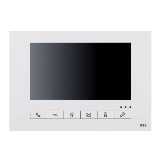
Product description Product description Control elements SD-Card Fig. 1: Control elements Function 7" color touch screen Communication button When an incoming call, press this button within 30 seconds to activate communication. Press it again to end call. Unlock button 3A Press this button to open the door when an incoming call or during a call. 3B Auto-unlock: The door is automatically opened 5 s after an incoming call. - Page 7 Product description System setting button Press this button to enter the system settings. Power indicator Always lights after power on. Alert indicator Always lights after arming and flashes when trigger alarm. Mute indicator Always lights after muting function is enable. Microphone Speaker Tab.1:...
-
Page 8: Feature
Product description Feature 3 different colors of appearance to meet personal esthetic preference ■ ■ Large 17.8 cm (7") and high-quality color TFT touch display with a resolution of 1024 x 600 pixel Support PoE or directly stand alone power supply ■... -
Page 9: Terminal Description
Product description Terminal description Fig. 2: Terminal description Function RJ45 network interface Plug in and plug out connector, 5P Connector for door bell Connector for power supply status Connector for zones Tab.2: Description │9 Operating Instructions 2TMD041700D0041... -
Page 10: Connection Of Zones
Product description 5.3.1 Connection of zones Connection of normally closed detectors [1] Single detector Detector Resistor Z (n) 10 K Fig. 3: Connection of single detector - normally closed [2] Multi detectors Detector n Detector 2 Detector 1 Resistor Z (n) 10 K Fig. - Page 11 Product description Note – Any of the eight zones can be connected as one of the above four ways, according to the actual situation. – For the connection of the same type of zones, please according to "Connection of multiple detectors" –...
-
Page 12: Technical Data
Technical data Technical data Designation Value Working voltage 27 VDC ≤100 mA Standby current ≤300 mA Working current ≤100 mA Zone working current Zone output voltage 12 VDC Display size 7" Display resolution 1024 x 600 Ringing: 30 s Duration Communication: 120 s Surveillance: 15 s Dimension... -
Page 13: Mounting/Installation
Mounting/Installation Mounting/Installation Warning Electric voltage! Dangerous currents flow through the body when coming into direct or indirect contact with live components. This can result in electric shock, burns or even death. – Disconnect the mains power supply prior to installation and/or disassembly! –... -
Page 14: Mounting
Mounting/Installation Mounting 7.2.1 Product dimension 218 mm 24.4 mm Fig. 7: Product dimension 7.2.2 Installation height 1.5 m 5 feet Fig. 8: Installation height │14 Operating Instructions 2TMD041700D0041... -
Page 15: Surface-Mounted Installation
Mounting/Installation 7.2.3 Surface-mounted installation Fig. 9: Surface-mounted installation 7.2.4 Dismantling Fig. 10: Dismantling │15 Operating Instructions 2TMD041700D0041... -
Page 16: Commissioning
Commissioning Commissioning Basic setting 8.1.1 Volume setting Fig. 11: Volume setting ■ Press the function button of the indoor station to open the "Basic setting" interface. ■ On the list on the left side, select "Volume", and then click "Select" to enter the setting interface. -
Page 17: Sound Setting
Commissioning 8.1.2 Sound setting Fig. 12: Sound setting ■ Press the function button of the indoor station to open the "Basic setting" interface. On the list on the left side, select "Sound", and then click "Select" to enter the setting ■... -
Page 18: Display Setting
Commissioning 8.1.3 Display setting Fig. 13: Display setting ■ Press the function button of the indoor station to open the "Basic setting" interface. ■ On the list on the left side, select "Display", and then click "Select" to enter the setting interface. -
Page 19: Date And Time Setting
Commissioning 8.1.4 Date and time setting Fig. 14: Date and time setting Press the function button of the indoor station to open the "Basic setting" interface. ■ ■ On the left side of the list, select "Date and time", and then click "Select" to enter the setting interface. -
Page 20: Language Setting
Commissioning 8.1.5 Language setting Fig. 15: Language setting ■ Press the function button of the indoor station to open the "Basic setting" interface. ■ On the list on the left side, select "Languages", and then click "Select" to enter the setting interface. -
Page 21: Black List Setting
Commissioning 8.1.6 Black list setting Fig. 16: Black list setting ■ Press the function button of the indoor station to open the "Basic setting" interface. ■ On the left side of the list, select "Black list", and then click "Select" to enter the setting interface. -
Page 22: Door Entry Setting
Commissioning 8.1.7 Door entry setting Fig. 17: Door entry setting Press the function button of the indoor station to open the "Basic setting" interface. On the list on the left side, select "Door entry", and then click "Select" to enter the setting interface. - Page 23 Commissioning Mini outdoor station Fig. 18: Private OS setting-mini outdoor station On the private OS setting page, In the "Device" drop-down list, select the mini outdoor station to be set. When there are multiple mini outdoor stations, "Copy Card" can be used to copy the current mini outdoor station card information to another mini outdoor station.
- Page 24 Commissioning Villa outdoor station Fig. 19: Private OS setting-villa outdoor station On the private OS setting page, In the "Device" drop-down list, select the villa outdoor station to be set. When there are multiple villa outdoor stations, each villa outdoor station must be set separately. " In "Default Lock", set the unlock time of the default lock of the villa outdoor station.
-
Page 25: Alarm Setting
Commissioning 8.1.8 Alarm setting Fig. 20: Alarm setting ■ Press the function button of the indoor station to open the "Basic setting" interface. ■ On the list on the left side, select "Alarm", and then click "Select" to enter the setting interface. -
Page 26: Resetting To Factory Default
Commissioning 8.1.9 Resetting to factory default Fig. 21: Reset factory default ■ Press the function button of the indoor station to open the "Basic setting" interface. ■ On the left side of the list, select " Reset Factory Default ", and then click "Select”. ■... -
Page 27: Reset Factory Password
Commissioning 8.1.10 Reset factory password Fig. 22: Reset factory password ■ Press the function button of the indoor station to open the "Basic setting" interface. ■ On the left side of the list, select "Reset Factory Password", and then click "Select”. ■... -
Page 28: Firmware Update
Commissioning 8.1.11 Firmware update Fig. 23: Firmware update ■ Press the function button of the indoor station to open the "Basic setting" interface. ■ On the left side of the list, select "Firmware Update ", and then click "Update". ■ The indoor station detects upgradeable programs in the SD card automatically. -
Page 29: Advanced Setting
Commissioning Advanced setting 8.2.1 Enter alarm setting Fig. 24: Enter alarm setting Press the function button of the indoor station to open the "Basic setting" interface. In the right corner, select "Advanced Setting". Input the programming password in the pop-up window. (The system default is 345678) Click "OK"... -
Page 30: Set Alarm Zone Position
Commissioning 8.2.2 Set alarm zone position Fig. 25: Set alarm zone position Click "Alarm Zone Position" -- "Select" to enter the configuration interface. On the alarm zone position settings page, single click on the floor plan to generate an alarm position. -
Page 31: Set Alarm Zone Attribute
Commissioning 8.2.3 Set alarm zone attribute Fig. 26: Setting an alarm zone attribute Click "Alarm Zone Attribute" -- "Select" to enter the configuration interface. On the alarm zone attribute settings page, select the appropriate zone and set the sensor type and alarm type. - Page 32 Commissioning Zone attribute description [1] Instant zone This type of zone will start detection when armed. Once the zone is triggered, an alarm is issued immediately. Turn off the alarm by disarming. [2] Delay zone This type of zone will raise an alarm when the people fail to exit or enter the delay zone in time. When the zone is armed, the detector starts the countdown for the exit delay and detects the area after the specified time.
- Page 33 Commissioning When the zone attributes have been set, the zone icon is displayed in green. Fig. 28: The zone is displayed in colour │33 Operating Instructions 2TMD041700D0041...
-
Page 34: Set Alarm System Timer
Commissioning 8.2.4 Set alarm system timer Fig. 29: Enter alarm system timer setting Click "Alarm System Timer" -- "Select" to enter the configuration interface. On the alarm system timer settings page, select a set of time templates and click "Edit Timer". │34 Operating Instructions 2TMD041700D0041... - Page 35 Commissioning Fig. 30: Set alarm system timer Select the effective number of days, start and end time, scope of application, etc., and click "OK" to return to the alarm system timer settings page. Check the time template that has already been set and click "OK" for it to take effect. │35 Operating Instructions 2TMD041700D0041...
-
Page 36: Engineering Setting Of Indoor Station
Commissioning Engineering setting of indoor station Please find details in the system manual. KNX setting Please find details in the system manual. │36 Operating Instructions 2TMD041700D0041... -
Page 37: Operation
Operation Operation Welcome screen and status bar Fig. 31: Welcome screen and status bar Function Set date and time. Display system information such as version, address and QR code. Please see the "Show system information" section for details. Display network connection status. Display unread records. -
Page 38: During A Call
Operation During a call Fig. 32: During a call When there is an incoming call, the resident can: Press the button to take the call. Press again to end the call. Press the button to release the door. The incoming call ends automatically 5 s later. Press the button to mute the ringtone of the indoor station. -
Page 39: Call Waiting
Operation Call waiting When there is a new incoming call during a call, two images are displayed on the screen. Fig. 33: Call waiting To take the second incoming call. The first conversation will be ended. To reject the second incoming call. To release the door for the second call. -
Page 40: Calling A Guard Unit
Operation Calling a guard unit Call default guard unit Press to call the default guard unit Press to end the call. Call designated guard unit Fig. 34: Call designated guard unit Press to enter the intercom UI. Input "#" + "Guard unit number", then press to call the designated guard unit. -
Page 41: Surveillance
Operation Surveillance 9.5.1 Surveillance overview Fig. 35: Surveillance overview Click here to choose surveillance targets. To surveil the villa outdoor station or mini outdoor station. To surveil the building outdoor station. To surveil the gate station. To surveil using the community cameras. To surveil using the home cameras. -
Page 42: Surveillance Of Outdoor Station
Operation 9.5.2 Surveillance of outdoor station Fig. 36: Surveillance of outdoor station To display the name of the surveillance device. The rest time of surveillance. To adjust the voice volume. (1-4) To display camera view. It is possible to switch to others if there are more than one. To release the subsidiary lock. -
Page 43: Home Monitor
Operation 9.5.3 Home monitor If the home’s cameras are used for surveillance, ensure the cameras and indoor station are on the same network. Fig. 37: Enter home monitor setting │43 Operating Instructions 2TMD041700D0041... - Page 44 Operation Fig. 38: Home monitor setting Input the user name and password of the camera to authorize the indoor station to use the camera for surveillance. │44 Operating Instructions 2TMD041700D0041...
- Page 45 Operation Fig. 39: Home monitor operation During the surveillance, click to take a snapshot manually. │45 Operating Instructions 2TMD041700D0041...
-
Page 46: Community Monitor
Operation 9.5.4 Community monitor If there are authorized cameras added on the PC management software, the resident can download the camera list to their own indoor station. Fig. 40: Download IP camera list │46 Operating Instructions 2TMD041700D0041... - Page 47 Operation Fig. 41: Community monitor │47 Operating Instructions 2TMD041700D0041...
-
Page 48: Intercom
Operation Intercom 9.6.1 Home to home intercom Press to enter the intercom UI. Input "Building number" + "Room number", then press to call another department. Fig. 42: Home to home intercom │48 Operating Instructions 2TMD041700D0041... -
Page 49: Room To Room Intercom
Operation 9.6.2 Room to room intercom Press to enter the intercom UI. If there are more than one indoor station in the same apartment, you can call the indoor station from the list. For convenience, you can name the indoor stations. Fig. - Page 50 Operation Fig. 44: Room to room intercom │50 Operating Instructions 2TMD041700D0041...
-
Page 51: Text Messages
Operation Text messages Press to enter the text message UI. You can view messages coming from the PC management software or create and send a message to the PC management software. When there are unread messages, will flash on the main screen. You can press it to view the messages. - Page 52 Operation Create and send a text message Fig. 46: Create and send a text message Title of the text message. Content of the text message. Click here to change between the English and Chinese input method. Click here to change between uppercase and lowercase. Click here to delete the previous character, as with the "Backspace"...
-
Page 53: Multi-Media
Operation Multi-media Create a catalog named "media" in the root directory of SD disk. Put the multi-media documents into this catalog. Insert the SD disk. Press then choose "Multimedia Player" Choose one media to play. Fig. 47: Multi-media Double click the image to switch between normal size and large size. Click to repeat play single media or medias by list. -
Page 54: Photo Album
Operation Photo album Create a catalog named "photo" in the root directory of SD disk. Put the photos into this catalog. Insert the SD disk. Press then choose "Photo album" Choose one picture to play. Fig. 48: Photo album Double click the image to switch between normal size and large size. Click to play the photos orderly like a photo frame. -
Page 55: Voice Message
Operation 9.10 Voice message Fig. 49: Create voice message │55 Operating Instructions 2TMD041700D0041... - Page 56 Operation Fig. 50: Play voice message Press to enter voice message setting. To create a new voice message. Press to start recording, press to stop recording. To listen to the existing voice. Press to play the voice message. To adjust the volume of the voice message. To set the current voice message as an absence message for visitors.
- Page 57 Operation Activate "Absence message for visitor" Fig. 51: Activate "Absence Msg for visitor" │57 Operating Instructions 2TMD041700D0041...
-
Page 58: Alarm
Operation 9.11 Alarm 9.11.1 Arm for away Click "Arm for Away", then input the password and click "OK". Fig. 52: Arm for away Click "Disarming" then input the password and click "OK". If you input a private password (the default is "123456") to arm the zones, you need also to input the private password again to disarm the zones. -
Page 59: Feedback Alarm Status
Operation 9.11.2 Feedback alarm status On the floor layout, the type and status of alarm are easily identifiable. Green = The devices are disarmed. Red = The devices are armed. Orange = The devices are triggered when armed. Fig. 54: Feedback alarm status │59 Operating Instructions 2TMD041700D0041... -
Page 60: Intelligent Community
Operation 9.12 Intelligent community Fig. 55: Intelligent community Click on the navigation bar to enter the intelligent community interface. Households may achieve community networking functions through the host computer and make inquiries regarding daily information, such as: bulletins, fee inquiries, useful numbers, weather forecasts, community navigation and business advertisements, etc. -
Page 61: I-Jia Operation
Operation 9.13 i-jia operation Fig. 56: Enter i-jia setting Premise: In the engineering mode of the indoor station, i-jia is selected for the smart home (default setting) Single click in the status bar to enter the i-jia interface. Click "Setting", enter the programming password 345678, and click "OK" to enter. Fig. - Page 62 Operation Fig. 58: i-jia operation On the i-jia operating interface, single click any device to control. It is possible to turn the page to see other devices. Click Scene to enter the scene control interface. │62 Operating Instructions 2TMD041700D0041...
-
Page 63: Knx Operation
Operation 9.14 KNX operation 9.14.1 KNX scene operation There are two methods of operating the scene mode of KNX. Method 1: On the welcome interface, click "Scene" and select a scene in the pop-up interface. Fig. 59: Enter KNX interface method 1 │63 Operating Instructions 2TMD041700D0041... - Page 64 Operation Method 2: On the welcome interface, click on the status bar to enter the KNX interface. Then single click "Scene" to select a scene in the pop-up interface. Fig. 60: Enter KNX interface method 2 │64 Operating Instructions 2TMD041700D0041...
-
Page 65: Knx Timer Setting
Operation 9.14.2 KNX timer setting Enter timer setting Fig. 61: Enter time setting On the welcome interface, single click on the status bar to enter the KNX interface. Click "Timer" to enter the settings interface. │65 Operating Instructions 2TMD041700D0041... - Page 66 Operation Single device timer Fig. 62: Enter single device timer setting Click "Single device timer" -- "Select" to enter the settings interface. On the settings interface, click an icon to enter specific settings. │66 Operating Instructions 2TMD041700D0041...
- Page 67 Operation Fig. 63: Single device timer setting Set the start and end times of the timer, the number of days it is to take effect and whether it should be repeated every working day or every day. Check “On" to activate and click "Save" to save. │67 Operating Instructions 2TMD041700D0041...
- Page 68 Operation Scene timer Fig. 64: Enter scene timer setting On the Timer interface, click "Scene timer" -- "Select" to enter the settings interface. On the Scene timer interface, click on a scene icon to enter specific settings. │68 Operating Instructions 2TMD041700D0041...
- Page 69 Operation Fig. 65: Scene timer setting In the same way, set the start and end times of the scene, the number of days it is to take effect and whether it should be repeated every working day or every day. Check “On"...
-
Page 70: Knx User Setting
Operation 9.14.3 KNX user setting Fig. 66: Enter KNX user setting interface On the welcome interface, single click on the status bar to enter the KNX interface. Click "Setting" and input 123456 in the pop-up window to enter the settings interface. │70 Operating Instructions 2TMD041700D0041... - Page 71 Operation Fig. 67: KNX user setting On the scene interface, click on a scene icon to enter specific settings. A scene’s icon and the scene’s name can be changed, and it can be associated with Arm for Away. Check “On" to activate and click "Save" to save. │71 Operating Instructions 2TMD041700D0041...
-
Page 72: Show History Records
Operation 9.15 Show history records Fig. 68: Show history records On the indoor station’s welcome interface, click “History" to enter the history interface. On this interface, the historical call log can be seen, as well as the taken and missed status. Click "Details..."... -
Page 73: Show System Information
Operation 9.16 Show system information Fig. 69: Show system information Click on the status bar to enter the system information interface. Firmware Version: view the firmware version Hardware Version: view the hardware version Address of Indoor Station: view the address of the indoor station IP-gateway address: view the IP gateway address (if there is a connected IP gateway) If indoor station is set as IP gateway address, there are three QR codes are provided to download apps. -
Page 74: Lock Screen
Operation 9.17 Lock screen Fig. 70: Lock screen When the screen is being cleaned, the screen can be locked temporarily for one minute to prevent a malfunction. Press and hold the icon on the status bar for 3 s, a screen lock window will pop up, and there will be a one minute countdown. -
Page 75: Call Elevator
Operation 9.18 Call elevator Fig. 71: Call elevator Premise: An elevator link function is set in the system. On the indoor station’s welcome interface, click "Elevator" to enter the call interface. On this interface, it is possible to see which floor the elevator is on and whether the elevator is going up or down. -
Page 76: Firmware Update
Operation 9.18.1 Firmware update Fig. 72: Firmware update ■ Press the function button of the indoor station to open the "Basic setting" interface. ■ On the left side of the list, select "Firmware Update ", and then click "Update". ■ The indoor station detects upgradeable programs in the SD card automatically. -
Page 77: Notice
We reserve the right to at all times make technical changes as well as changes to the contents of this document without prior notice. The detailed specifications agreed to at the time of ordering apply to all orders. ABB accepts no responsibility for possible errors or incompleteness in this document. - Page 78 Km 9 National Highway 1A , The detailed specifications agreed P.O.Box 11070 Dubai-UAE Hoang Liet, Hoang Mai, Hanoi, upon apply for orders. ABB accepts T : +971 4 3147 586 Vietnam no responsibility for possible errors F : +971 4 3401 541 T : +84 4 3861 1010 or incompleteness in this document.