
Related Manuals for Siemens SITRANS F C MASSFLO MASS 6000 Ex-d


Summary of Contents for Siemens SITRANS F C MASSFLO MASS 6000 Ex-d
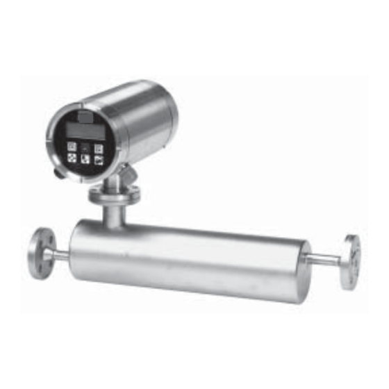
- Page 1 Manual SITRANS F C MASSFLO MASS flowmeters Signal converter type MASS 6000 Ex-d sensor type MASS 2100 compact or remote mounted Order no.: FDK:521H1178 *083R9506* SFIDK.PS.028.Q1.02 - A5E00253712...
-
Page 2: Table Of Contents
• Siemens Flow Instruments want to assist by estimating the chemical resistance of the sensor parts that are in connection with the media, but it is at any time the customer’s... -
Page 3: Installation
SITRANS F C MASSFLO 2. Installation Installation Category 2 equipment May be installed in zone 1 and zone 2. 2.1 Compact Category 1 equipment 2.2 Remote Sensor MASS 2100 may be installed in zone 0, zone 1 and zone 2. -
Page 4: Ex Survey According To Directive 94/9/Ec (Atex)
SITRANS F C MASSFLO 2. Installation II 2G E Ex ia IIC T6 as an example 2.3 Ex survey according to Directive 94/9/EC (ATEX) Instrument groups Applies to instruments used in underground mining operations, as well as their above ground operations, which can be endangered by mine gas and/or flammable dusts. -
Page 5: Overview
SITRANS F C MASSFLO 2. Installation 2.4 Overview A = EEx e (Increased safety) B = EEx ia (Intrinsic safety) MASS 6000 Ex-d Flameproof enlosure C = EEx d (Flameproof safety) EEx de [ia/ib] IIC T6 1. -
Page 6: Device Identification
SITRANS F C MASSFLO 2. Installation 2.5 Device identification Sensor MASS 2100 label Signal converter MASS 6000 Ex-d label Meaning Notified body for QA supervision: UL International DEMKO A/S, Denmark Explosion protected ATEX Equipment Group and Protection Category Maximum medium temperature EC Approval Numbers and Protection Type Production year... -
Page 7: Approvals
SITRANS F C MASSFLO 2. Installation Sensor MASS 2100 DI 1.5, DI 3, DI 6, DI 15, DI 25 and DI 40 2.6 Approvals 0539 II 1 G DEMKO 03 ATEX 135252X EEx ia IIC T3...T6 Temperature classes for ambient temperature between −... -
Page 8: Mounting Of Signal Converter Compact Or Remote
SITRANS F C MASSFLO 2. Installation 2.8 Mounting of signal For compact installation mount the converter converter compact or on top of the sensor interface. Please make remote sure that it is correctly oriented (note the little tap). -
Page 9: Electrical Connection
SITRANS F C MASSFLO 3. Electrical connection 3.1 Electrical connection Turn off the power supply before connecting input and output cables and wait 30 compact or remote minutes before unscrewing the lid. Mounting and connection View A EEx e M20 black ATEX approved gland, power supply cable "e". - Page 10 SITRANS F C MASSFLO 3. Electrical connection 3.1 Electrical connection compact or remote (continued) Important Electrical connections are made through the front of the signal converter (view A), in the terminal housing. This housing is accessed by removing the front cover described in chapter 2. Read the chapter 4.
-
Page 11: Setting Of Active Or Passive Current Out-Put Mode
SITRANS F C MASSFLO 3. Electrical connection 3.2 Setting of active or The current output in MASS 6000 can operate passive current out- in either active or passive mode to make elec- put mode trical connection as easy as possible. The current output in MASS 6000 is default set to active mode. -
Page 12: Installation Of Add-On Module (Aom)
SITRANS F C MASSFLO 3. Electrical connection 3.4 Installation of Disconnect the equipment from the supply add-on module (AOM) circuits and wait 30 min. for dischanging the energy in the internal electronics before opening. View C Remove the rear cover, by loosening the safety EEx d tap allen screw (M3) and turn the rear cover... -
Page 13: Installation Examples
SITRANS F C MASSFLO 3. Electrical connection 3.5 Installation examples Current output in passive mode Frequency/pulse output in passive mode HART output Intrinsically safe data "ia", please look into the "Technical data" in chapter 4. SFIDK.PS.028.Q1.02... -
Page 14: Technical Data
SITRANS F C MASSFLO 4. Technical data Technical data 4.1 Sensor MASS 2100. Versions DI 1.5, DI 3, DI 6, DI 15, DI 25, DI 40 Versions DI 1.5 DI 3 DI 6 DI 15 DI 25 DI 40 inch... -
Page 15: Signal Converter Mass 6000 Ex-D
4. Technical data SITRANS F C MASSFLO 4.2 Signal converter MASS 6000 Ex-d MASS 6000 Ex-d Mass flow [kg/s], volume flow [l/s], fraction [%], °Brix, density [kg/m Measurement of ], temperature [°C] Current output Classified Ex ia, selectable as active or passive outputs. Default setting is passive mode Current 0-20 mA or 4-20 mA <... - Page 16 SITRANS F C MASSFLO 4. Technical data 4.2 Signal converter MASS 6000 Ex-d (continued) Enclosure Material Stainless steel AISI 316 W1.4435 Rating Compact mounted on sensor, IP 67 to IEC 529 and DIN 40050 Remote mounted, IP 65 to IEC 529 and DIN 40050 Load 18 - 1000 Hz random, 1.14 G rms, in all directions, to IEC 68-2-36, Curve E EMC performance...
-
Page 17: Output Characteristic Mass 6000
SITRANS F C MASSFLO 4. Technical data 4.3 Output characteristic Output Bidirectional mode Unidirectional mode MASS 6000 characteristics 0-20 mA 4-20 mA Frequency Pulse output Relay Power supply off Power supply on Error relay No error Error Limit switch or 1 set point... -
Page 18: Commissioning
SITRANS F C MASSFLO 5. Commissioning Commissioning Keypad and display layout Keypad The keypad is used to set the flowmeter. The function of the keys are as follows: TOP UP KEY This key (hold 2 sec.) is used to switch between operator menu and setup menu. -
Page 19: Menu Build-Up
SITRANS F C MASSFLO 5. Commissioning Menu build-up The menu structure of a specific type of signal converter is shown in a menu overview map. Details of how a specific parameter is set is shown in a menu detail map for the specific parameter. The menu structure is valid for the title and subtitle line only. -
Page 20: Menu Overview
SITRANS F C MASSFLO 5. Commissioning 5.3 Menu overview SFIDK.PS.028.Q1.02... -
Page 21: Menu Details
SITRANS F C MASSFLO 5. Commissioning 5.4 Menu details Basic settings menu The decimal point for flowrate, totalizer 1 and totalizer 2 can be individually positioned. • open the respective window. • ensure that the cursor is positioned below the decimal point. Use the SELECT KEY •... -
Page 22: Outputs Setting Menu
SITRANS F C MASSFLO 5. Commissioning 5.5 Outputs setting menu Current output The current output must be set off when not used. Digital output Pulse Digital output Frequency SFIDK.PS.028.Q1.02... - Page 23 5. Commissioning SITRANS F C MASSFLO Digital output Batch Relay output Error level (Also possible through digital output) Acceptance level is set in the basic settings menu. Error number (Also possible through digital output) Limit switch & direction switch (Also possible through digital output)
-
Page 24: Reset Mode
The standard deviation (Zero Sigma) must be within a window, which is predefined by Siemens Flow Instruments . This window is called Sigma Limit. If the standard deviation is outside the window the following message is shown in the display: “Zero Sigma exceeds Sigma Limit”. -
Page 25: Service
SITRANS F C MASSFLO 6. Service Service Error Error text #Comment Outputs Input 6.1 List of error numbers Remedy text status status I1 - Power on Power on has activated Active Active I2 - Add-on module Applied A new module has been added to the system Active... -
Page 26: Trouble Shooting Mass 6000
SITRANS F C MASSFLO 6. Service 6.2 Trouble shooting Symptom Output Error Cause Remedy MASS 6000 signals code Empty display Minimum 1. Supply voltage 1. Check supply voltage 2. MASS 6000 defective 2. Replace MASS 6000 No flow signal Minimum 1. -
Page 27: Ordering
Standard ..........................................Density ..........................................Brix/Plato ........................................... Fraction flow (specified by customer), contact Siemens Flow Instruments ..................... Flow calibration Standard calibration included in sensor (3 flow x 2 points) ............................Standard calibration, matched pair (3 flow x 2 points; FDK:085F7351) ........................ -
Page 28: Build-Up Ordering - High Pressure Versions
Standard ..........................................Density ..........................................Brix/Plato ........................................... Fraction flow (specified by customer), contact Siemens Flow Instruments ...................... Flow calibration Standard calibration included in sensor (3 flow x 2 points) ............................Standard calibration, matched pair (3 flow x 2 points; FDK:085F7351) ........................ -
Page 29: Signal Converter Mass 6000 Ex-D For Remote Mounting
SITRANS F C MASSFLO 7. Ordering 7.3 Signal converter Description Version Supply voltage Code No. Symbol MASS 6000 MASS 6000 signal converter 1 current output 24 V a.c./d.c. FDK:083H0216 Ex-d for remote EEx-d remote 1 frq./pulse output mounting EEx de [ia/ib] T3-T6 version 1 relay output... -
Page 30: Certificates
SITRANS F C MASSFLO 8. Certificates 8.0 Download certificates Please go to http://www.siemens.com/flow 8.1 EC-declaration of conformity SFIDK.PS.028.Q1.02... -
Page 31: Ec Type Examination Certificate
SITRANS F C MASSFLO 8. Certificates 8.2 EC type examination certificate SFIDK.PS.028.Q1.02... - Page 32 Suggestions for improvement registration of a utility model or design, are reserved. are always welcomed. Technical data subject to change without prior notice. Copyright © Siemens AG 04.2003 All Rights Reserved Siemens Flow Instruments A/S Order no.: FDK:521H1178-01 Nordborgvej 81...