Advertisement
Quick Links
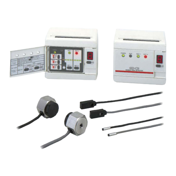
Metal-sheet Double-feed Detector
GD Series
●
●
WARNING
●
1
OUTLINE
● This product detects double feeds of metal sheets, lead frames, etc.
The sensitivity is easily set by teaching with actual samples.
2
FUNCTIONAL DESCRIPTION
Description
①
Panel cover
②
・Lights up when the power is ON.
Power indicator (Green)
・
Specifies whether channel selection is by panel operation,
by external channel select inputs, or through RS-232C com-
munication.
□PANEL: Selection is by channel select key.
□LOCK: Locks channel selection. In case of GD-C2, this is
GD-C2:
RS-232C
□EXT.: Selection is by external channel select inputs.
・
The table below gives the key and external input operation
for each channel selection method.
Operation
RUN / SET selection
③
Timer mode selection
Channel select key
SET-1
(CH-SELECT)
SET-2
0-ADJ.
Channel shift
RUN / SET
SET-1
SET-2
IN-0
IN-1
IN-2
Note: The RUN / SET selection with the SET-MODE key on
the panel is effective only when the RUN / SET selec-
tion input is High (RUN mode).
・SET mode: Lights up under normal condition.
Self-diagnosis indicator
④
(Red)
RUN mode: Lights up on error.
・
Indicates the sensing mode.
・
Lights up green: Normal sensing mode
Sensing mode indicator
・
Lights up yellow: Precise sensing mode
⑤
(Green, Yellow)
・
Refer to '●Sensing Mode' in '
FUNCTIONS'.
Phone: 800.894.0412 - Fax: 888.723.4773 - Web: www.clrwtr.com - Email: info@clrwtr.com
INSTRUCTION MANUAL
MJE-GD(03) No.0030-70V
Never use this product as a sensing device for personnel protection.
In case of using sensing devices for personnel protection, use products which meet laws and standards, such as
OSHA, ANSI or IEC etc., for personnel protection applicable in each region or country.
Make sure to use the sensor heads and controllers in the specified combinations. If they are used in any other com-
bination, the sensor heads may get damaged.
①
Function
-
also the setting for channel selection by external
device through RS-232C.
Mode
LOCK
PANEL
(RS-232C)
○(Note)
○(Note)
○
○
○
○
○
○
○
○
○
○
○
○
○
○
○
6
EXPLANATION OF
Thank you very much for using Panasonic products. Please read this
Instruction Manual carefully and thoroughly for the correct and opti-
mum use of this product. Kindly keep this manual in a convenient
place for quick reference.
②
③
④
⑤
⑥
⑦
⑧
POWER
ALM.
OUT-1
OUT-2
CH-SELECT
PANEL
RS232C
EXT.
SENS.
TIMER
CH
NORM.
OFD.
SET-1
SET-2
0-ADJ.
SET-MODE
RUN
SET
⑮
⑭ ⑬ ⑫
⑪
Description
Comparative output-1
⑥
(OUT-1) indicator (Green)
Comparative output-2
⑦
(OUT-2) indicator (Red)
Sensing level indicator
⑧
(Yellow × 1, Green × 6)
○: Operable
EXT.
○(Note)
⑨
Channel display
○
○
○
○
○
⑩
Channel shift key
○
⑪ SET-2 key
○
⑫ SET-1 key
○
⑬ Zero adjustment (0-ADJ.) key
○
○
⑭ SET-MODE key
⑮ TIMER key
⑨
⑩
Function
・
Lights up when OUT-1 is OFF.
・
Blinks twice on completion of zero adjustment (0-ADJ.) or
SET-1 setting in SET mode.
・
Lights up when OUT-2 is OFF.
・
Blinks twice on completion of zero adjustment (0-ADJ.) or
SET-2 setting in SET mode.
・
Seven LEDs show the sensing level.
・More the number, thicker or larger the object sheets are,
more are the LEDs which light up.
・
LEDs light up one after the other during teaching.
・
All LEDs blink at the same time if the teaching fails.
・Shows the present channel (1 to 8).
・
Blinks during SET mode.
・
The decimal point informs whether the set level data has
been stored.
Lights up
Turns off
Decimal point
・
When an error occurs, the display indicates the error code.
・
Refer to '●Self-diagnosis (Alarm) function' in '
PLANATION OF FUNCTIONS'.
・The channel can be selected by the channel shift key when
CH-SELECT is set at PANEL.
・Sets the two-sheet threshold level (larger number of sheets).
・Sets the one-sheet threshold level (smaller number of sheets).
・Calibrates zero level under sheet non-existing condition.
・Switches between RUN mode and SET mode.
□RUN: Detection takes place.
□SET: Set-up is done.
・Switches timer mode.
□NORM. mode: Timer not used.
□OFD. mode: Delay timer (50ms approx.) used.
Stored
Not stored
6
EX-
Advertisement

Related Manuals for Panasonic GD-3


Summary of Contents for Panasonic GD-3
- Page 1 Thank you very much for using Panasonic products. Please read this INSTRUCTION MANUAL Instruction Manual carefully and thoroughly for the correct and opti- mum use of this product. Kindly keep this manual in a convenient place for quick reference. Metal-sheet Double-feed Detector GD Series MJE-GD(03) No.0030-70V...
- Page 2 Make the sender and receiver face each other and align their sensing center line. Keep a distance from any magnet or a device generating magnetic field. It may degrade the detectability. Mounting of sensor heads GD-10 GD-3 Set screw <Fixing at one point> <Fixing at two points>...
-
Page 3: Sensitivity Setting
CONNECTION Wiring diagram Sender Receiver Color code 12 to 24V DC 10% Non-voltage contact or NPN open-collector transistor White 0V (Note) Shield OUT-1 White OUT-2 Load Black ALM. (Self-diagnosis output) Load Load Shield 0V (Note) RUN / SET 30V DC or less IN-0 Low: 0 to 1V, High: 4.5 to 30V, or open SET-1... -
Page 4: Explanation Of Functions
EXPLANATION OF FUNCTIONS Sensing mode The GD series has two sensing modes, one is the normal sensing mode and the other is the precise sensing mode. They are automatically se- lected by the characteristics of the object. The GD series goes into this mode when the num- The GD series goes into this mode when the number Normal sensing Precise sensing... - Page 5 Response time The controllers GD-C1 and GD-C2 automatically select the most suitable signal processing method, according to the material and thickness of the sensing object. Depending on the selected signal processing method, the response time is also automatically determined as either '5ms or less', or '30ms or less'.
-
Page 6: Specifications
Notes: 1) Since it is possible that GD-3 may get damaged if controllers GD-C1 or GD-C2 are connected to it, make sure to use controller GD-C3 along with GD-3. The above detectable sheet thicknesses are typical data at the given sensing distance. The allowable thickness will differ from the range described in the above ta- ble at other setting distances.