Table of Contents
Advertisement
Quick Links
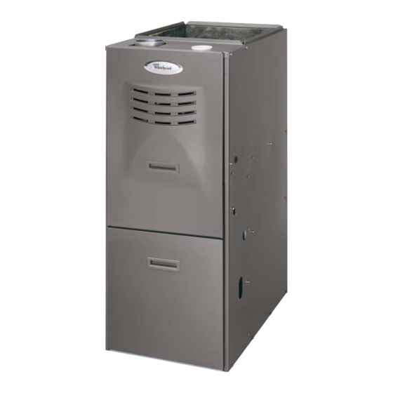
80% 2-STAGE VARIABLE SPEED GAS FURNACE
GAS FURNACE SAFETY................................................................1
INSTALLATION REQUIREMENTS ................................................3
Tools and Parts ............................................................................3
Location Requirements................................................................3
Installation Configurations ...........................................................4
Ductwork Requirements ..............................................................4
Electrical Requirements ...............................................................5
Gas Supply Requirements ...........................................................5
Venting Requirements..................................................................5
INSTALLATION INSTRUCTIONS ..................................................7
Inspect Shipment .........................................................................7
Plan Vent System .........................................................................7
Determine Vent Pipe Direction...................................................12
Connect Venting.........................................................................13
We have provided many important safety messages in this manual and on your appliance. Always read and obey all safety
messages.
This is the safety alert symbol.
This symbol alerts you to potential hazards that can kill or hurt you and others.
All safety messages will follow the safety alert symbol and either the word "DANGER" or "WARNING."
These words mean:
WARNING
All safety messages will tell you what the potential hazard is, tell you how to reduce the chance of injury, and tell you what can
happen if the instructions are not followed.
™
Whirlpool Gold
Models
WGFBT, WGFBLT
47724K005
INSTALLATION INSTRUCTIONS
GAS FURNACE SAFETY
Your safety and the safety of others are very important.
DANGER
Table of Contents
Install Ductwork..........................................................................13
Filter Specifications ....................................................................14
Make Electrical Connections .....................................................14
Make Gas Connections..............................................................15
Check the Furnace Input Rate ...................................................16
Adjust the Furnace Input Rate ...................................................16
Complete Installation..................................................................17
Shut Down..................................................................................18
Sequence of Operation ..............................................................19
Controls ......................................................................................20
TROUBLESHOOTING ..................................................................21
ASSISTANCE OR SERVICE .........................................................24
Accessories ................................................................................24
WARRANTY ..................................................................................25
You can be killed or seriously injured if you don't immediately
follow instructions.
You can be killed or seriously injured if you don't follow
instructions.
Whirlpool
®
Home Cooling and Heating
14610 Breakers Drive
Jacksonville, FL 32258
Advertisement
Table of Contents

Related Manuals for Whirlpool WGFBLT


Summary of Contents for Whirlpool WGFBLT
-
Page 1: Table Of Contents
All safety messages will tell you what the potential hazard is, tell you how to reduce the chance of injury, and tell you what can happen if the instructions are not followed. Whirlpool ® Home Cooling and Heating ™ Whirlpool Gold Models 14610 Breakers Drive WGFBT, WGFBLT Jacksonville, FL 32258 47724K005... - Page 2 IMPORTANT SAFETY INSTRUCTIONS Use only with type of gas approved for this furnace. When a furnace is installed so that supply ducts carry Refer to the furnace rating plate. air circulated by the furnace to areas outside the space containing the furnace, the return air shall also Install this furnace only in a location and position as be handled by duct(s) sealed to the furnace casing specified in the Location Requirements section of...
-
Page 3: Installation Requirements
INSTALLATION REQUIREMENTS These instructions are intended as a general guide only for use by qualified persons and do not supersede any national or local Location Requirements codes in any way. Compliance with all local, state, or national codes pertaining to this type of equipment should be determined WARNING prior to installation. -
Page 4: Installation Configurations
In a residential garage, a gas-fired furnace must be installed so the burner(s) and the ignition source are located not less Installation Configurations than 18" above the floor. The furnace is to be located or protected to avoid physical damage by vehicles. Upflow Installations Furnaces may be installed as suspended units in the horizontal position. -
Page 5: Electrical Requirements
Existing Venting Systems Electrical Requirements When an existing furnace is removed or replaced, the original WARNING venting system may no longer be sized to properly vent the attached appliances. An improperly sized venting system can result in spillage of flue products into the living space, the formation of condensate, leakage, etc. - Page 6 Venting Options Contaminated Combustion Air The furnace can be installed as either direct vent or nondirect Excessive exposure to contaminated combustion air will result in vent unit. performance-related problems. The recommended source of combustion air is outdoor air. For either type of installation, special venting considerations must be followed.
-
Page 7: Installation Instructions
INSTALLATION INSTRUCTIONS WARNING Plan Vent System Confined Space Installation—Direct Venting If the furnace is installed in a confined space and all the air necessary for combustion is supplied to the furnace through an air intake pipe vented directly outside, the pipe size and materials used must conform to the specification listed in Explosion Hazard “Materials—Air Intake Pipe Only”... - Page 8 Optional Attic Inlet Air Piping and Fitting Specifications NOTE: Attic must be well ventilated. ASTM Gable Vent Piping and Fitting Material Specification Schedule 40 PVC (Pipe) D1785 12" Minimum Schedule 40 PVC (Cellular Core Pipe) F891 Schedule 40 PVC (Fittings) D2466 SDR-26 (Pipe) D2241...
- Page 9 Equipment in Confined Space—All Air from Inside Equipment in Confined Space—All Air from Outside (All air through ventilated attic) A. Chimney or gas vent D. Outlet air B. Furnace E. Inlet air (ends 12" above bottom) C. Ventilation louvers F. Water heater A.
- Page 10 Vertical Venting Sidewall Venting Category I furnaces must be vented vertically or nearly vertically. This furnace can be sidewall (horizontally) vented with a listed Common venting and multistory venting are permitted when sidewall venter such as Field Controls Model SWG-4HD with CK- done in accordance with applicable codes, such as local and 43 Control Kit, or Tjernlund Model GPAK-JT.
- Page 11 Factory-Built Chimney Venting Chimney Options The furnace must be connected to a factory-built chimney or vent complying with a recognized standard, or a masonry or concrete chimney lined with a lining material acceptable to the authority with jurisdiction. NOTE: Venting into an unlined masonry chimney or a single wall metal vent is prohibited in all cases.
-
Page 12: Determine Vent Pipe Direction
Determine Vent Pipe Direction The vent system of the furnace must be self-supporting and must Vertical Venting not apply any weight load to the combustion blower. A vertical vent should extend through the roof a minimum of 2 ft and not be obstructed a minimum of 10 ft in any direction. Combustion Air Sources Horizontal Venting There are 2 sources for combustion air:... -
Page 13: Connect Venting
Sidewall Vent Terminal Clearances—Nondirect Vented Furnaces (Horizontal Venting) Vent Terminal Air Supply Inlet Area Where Terminal Is Not Permitted U.S. Installations Clearance above grade, veranda, porch, deck, or balcony 12" Clearance to window or door that may be opened 4 ft below or to side of opening; 12" above opening Clearance to permanently closed window Vertical clearance to ventilated soffit located above the terminal within a horizontal distance of 2 ft from the center line of the terminal... -
Page 14: Filter Specifications
Minimum Filter Requirements Chart Installation with Return Ducts Disposable Filters Cleanable Filters A return air duct system is recommended. If the unit is installed in a confined space or closet, a return connection must be run, full Min. Min. size, to a location outside the closet. The air duct in the closet Airflow Area Area... -
Page 15: Make Gas Connections
5. Using UL listed wire nuts, connect the field supply wires to the furnace (black to black and white to white). Make Gas Connections IMPORTANT: This furnace requires conversion for use with propane. To order the correct conversion kit, see “Accessories.” 1. -
Page 16: Check The Furnace Input Rate
7. Remove the inlet pressure tap plug on the gas control valve and connect pressure gauge to the ¹⁄₈" NPT inlet Adjust the Furnace Input Rate pressure tap. (if required) 8. Turn on the gas supply at the manual gas shutoff valve. 9. -
Page 17: Complete Installation
10. Move the gas control switch to the OFF position. NOTE: If more than one run of return or heated air ducts are used, air temperature measurements should be taken in each 11. Disconnect the pressure gauge from the ¹⁄₈" NPT outlet duct. -
Page 18: Shut Down
Heating Mode Single Stage Thermostat Operation The unit as shipped is factory set to run at the middle of the heating rise range as shown on the unit rating plate. If higher or The automatic heat staging option allows a single stage lower rise is desired, change the rise 15% up or down by moving thermostat to be used with a two-stage WGFE furnace. -
Page 19: Sequence Of Operation
Sequence of Operation When the second stage call for heat is satisfied, the ignition Heating control closes the gas control valve and runs the combustion blower for an additional 15 seconds. The circulating air blower On a call for first stage heat (W1) from the room thermostat, the continues to run for approximately 120 seconds at 82% of the ignition control performs a 1-second self-check. -
Page 20: Controls
Controls Following is a description of the operation of some of the controls Primary Limit Control used in this furnace. All models use one of each control, except as noted. This is a normally closed control that opens if abnormally high circulating air temperatures occur. -
Page 21: Troubleshooting
TROUBLESHOOTING Furnace Fails to Operate Properly CFM LED Review “Sequence of Operation” and visually inspect the On these models, an amber LED is provided on the control board following before troubleshooting: to display CFM. To determine what CFM the motor is delivering at any time, count the number of times the amber LED flashes. - Page 22 Wiring Connection Diagram Check codes for proper wiring and circuit protection before 3. Proper polarity must be observed for field line voltage supply; installation. ignition control will lock out if polarity is reversed. NOTES: 4. For temporary service replacement of circulating blower motor with a PSC motor, connect desired speed tap to EAC 1.
- Page 23 Wiring Schematic (LOW) (DRAIN)
-
Page 24: Assistance Or Service
® Whirlpool Home Cooling and Heating To order accessories ask for the appropriate part number listed 14610 Breakers Drive below or contact your Whirlpool ® Home Cooling and Heating Jacksonville, FL 32258 dealer. Please include a daytime phone number in your correspondence. - Page 26 Notes...
- Page 27 Notes...
- Page 28 WFCH, which is located on Serial number __________________________________________________ the outside of the product. Installation date ________________________________________________ 47724K005 ®Registered Trademark/TM Trademark of Whirlpool, U.S.A., 11/05 © 2005. All rights reserved. Manufactured under license by Tradewinds Distributing Company, LLC., Coconut Grove, Florida Printed in U.S.A.