
Related Manuals for Huawei OptiX OSN 7500


Summary of Contents for Huawei OptiX OSN 7500
- Page 1 HUAWEI OptiX OSN 7500 Intelligent Optical Switching System Technical Manual System Description V100R001 Huawei Technologies Proprietary...
- Page 2 T2-040284-20050308-C-1.10 Product Version V100R001 31026684 Huawei Technologies Co., Ltd. provides customers with comprehensive technical support and service. Please feel free to contact our local office or company headquarters. Huawei Technologies Co., Ltd. Address: Administration Building, Huawei Technologies Co., Ltd., Bantian, Longgang District, Shenzhen, P. R. China Postal Code: 518129 Website: http://www.huawei.com...
- Page 3 Quidview, Musa, Airbridge, Tellwin, Inmedia, VRP, DOPRA, iTELLIN, HUAWEIOptiX, C&C08 iNET, NETENGINE, OptiX, iSite, U-SYS, iMUSE, OpenEye, Lansway, SmartAX, infoX, TopEng are trademarks of Huawei Technologies Co., Ltd. All other trademarks and trade names mentioned in this manual are the property of their respective holders.
- Page 4 Summary of Updates This section provides the update history of this manual and introduces the contents of subsequent updates. Update History Manual Version Notes T2-040284-20050308-C-1.10 Initial field trial release Huawei Technologies Proprietary...
-
Page 5: Table Of Contents
OptiX OSN 7500 Technical Manual - System Description Contents Contents 1 Overview of the OptiX OSN 7500 2 Functions 2.1 Capacity 2.1.1 Cross-Connect Capacity 2.1.2 Slots Access Capacity 2.1.3 High Integration Design 2.2 Service 2.2.1 SDH/PDH Service 2.2.2 Ethernet Services 2.2.3 ATM Services... - Page 6 OptiX OSN 7500 Technical Manual - System Description Contents 2.7.2 Network Level Protection 2-11 2.8 DCN Communication 2-12 3 Hardware 3-13 3.1 Cabinet 3-13 3.2 Subrack 3-15 4 Boards 4.1 Type 4.2 Slot 4.2.1 SDH Interface Unit 4.2.2 PDH Interface Unit 4.2.3 Data service Interface Unit...
- Page 7 OptiX OSN 7500 Technical Manual - System Description Contents 7 Intelligent Features 7.1 SLA Service 7.2 Automatic End-to-End Service Configuration 7.3 Mesh Networking 7.4 Traffic Engineering 7.5 Integrated Intelligent Service Application 8 Protection 8.1 Equipment Level Protection 8.1.1 TPS Protection for Tributary Boards 8.1.2 TPS Protection for Ethernet Boards...
- Page 8 OptiX OSN 7500 Technical Manual - System Description Contents 10.1 Optical Interface Performance 10-1 10.1.1 SDH Optical Interface 10-1 10.1.2 Ethernet Optical Interface 10-6 10.1.3 ATM Optical Interface 10-7 10.2 Electrical Interface Performance 10-7 10.2.1 PDH Electrical Interface 10-8 10.3 Clock Performance 10-8 10.3.1 Clock Interface Type...
- Page 9 Figure 1-1 Outer view of the OptiX OSN 7500 Figure 1-2 Application of the OptiX OSN 7500 in the network Figure 2-1 Access capacity of service slots of the OptiX OSN 7500 Figure 3-1 Outer view of the ETSI cabinet...
- Page 10 OptiX OSN 7500 Technical Manual - System Description Figures Figure 6-13 EVPL accessing, forwarding and stripping 6-15 Figure 6-14 EVPL service convergence 6-16 Figure 6-15 EVPLAN service 6-17 Figure 6-16 Wrapping protection 6-18 Figure 6-17 Steering protection 6-19 Figure 6-18 Application of Band exclusive ATM Services...
- Page 11 Table 2-5 Basic networking modes for the OptiX OSN 7500 Table 2-6 Equipment level protection provided by the OptiX OSN 7500 2-11 Table 2-7 Maximum number of MSP rings supported by the OptiX OSN 7500 2-12 Table 3-1 Technical parameters of the ETSI cabinett...
- Page 12 Table 10-1 Performances of the STM-1 optical interface of the OptiX OSN 7500 10-1 Table 10-2 Performances of the STM-4 optical interface of the OptiX OSN 7500 STM-4 10-2 Table 10-3 Performances of the STM-16 optical interface of the OptiX OSN 7500...
- Page 13 OptiX OSN 7500 Technical Manual - System Description 1 Overview of the OptiX OSN 7500 About This Manual Related Manuals Manual Volume Usage OptiX OSN 7500 Intelligent Optical System Introduces the functionality, structure, Switching System Technical Manual Description performance, specifications, and theory of the product.
- Page 14 This part introduces the mechanical structure and the adaptable cabinet installation of the OptiX OSN 7500. Chapter 4 Boards This part lists all the available boards in the OptiX OSN 7500 and introduces their installation slots. Chapter 5 Software This part introduces the system software structure and functions of each part.
- Page 15 OptiX OSN 7500 Technical Manual - System Description 1 Overview of the OptiX OSN 7500 Intended Audience This manual is intended for: Network planner Network designer Network administrator Conventions The manual uses the following conventions. Symbol Conventions Symbol Description A warning notice with this symbol indicates a risk of personal injury.
-
Page 16: Overview Of The Optix Osn 7500
(the OptiX OSN 7500 for short) in the optical transmission network. The OptiX OSN 7500 is a piece of new generation equipment that Huawei develops based on what the metropolitan area network (MAN) is like and its development trend in the future. -
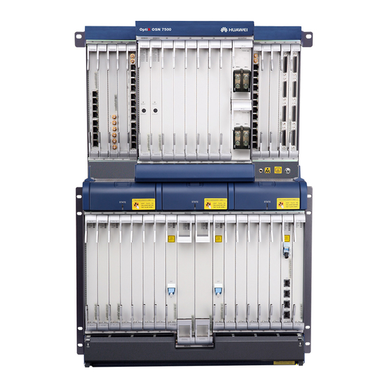
Page 17: Figure 1-1 Outer View Of The Optix Osn 7500
Technical Manual - System Description 1 Overview of the OptiX OSN 7500 Figure 1-1 Outer view of the OptiX OSN 7500 As an intelligent optical core switching system with large capacity, the OptiX OSN 7500 is mainly used at the backbone layer of the MAN to groom and transmit various services with different granules. -
Page 18: Figure 1-2 Application Of The Optix Osn 7500 In The Network
Figure 1-2 Application of the OptiX OSN 7500 in the network The OptiX OSN 7500 is gradually used on the core convergence node of large cities, the optical core switching (OCS) of medium and small cities, and service grooming on provincial trunks. -
Page 19: Functions
This chapter introduces the functions of the OptiX OSN 7500 as follows: Capacity Service Interface Intelligent features Networking Resilient packet ring Protection Capacity 2.1.1 Cross-Connect Capacity The OptiX OSN 7500 provides two types of SDH cross-connect board: GXCSA and GXCSB. Table 2-1 shows their cross-connect capacity. Huawei Technologies Proprietary... -
Page 20: Slots Access Capacity
1280 VC-4) VC-12) or (768 x 768 VC-3) 2.1.2 Slots Access Capacity The OptiX OSN 7500 provides 22 service slots, with the maximum access capacity of 200 Gbit/s. Figure 2-1 shows the access capacity of each slot. Huawei Technologies Proprietary... -
Page 21: High Integration Design
Figure 2-1 Access capacity of service slots of the OptiX OSN 7500 2.1.3 High Integration Design The dimensions of the OptiX OSN 7500 subrack are 757 mm (H) x 497 mm (W) x 295 mm (D). A single subrack has 22 slots for processing boards and 8 slots for interface boards. -
Page 22: Service
SDH with FEC: 10.71 Gbit/s, 2.66 Gbit/s Standard PDH: E1/DS1, E3/DS3, E4 2.2.2 Ethernet Services The OptiX OSN 7500 provides EFS4, EFS0, EGS2, EGT2 and EFT8 Ethernet boards to satisfy the requirements of different Ethernet services transmission. FE electrical Ethernet service... -
Page 23: Built-In Wdm Technology
50ms. 2.2.6 Service Access Capability The capacity of services that the OptiX OSN 7500 can access varies with the type and quantity of the configured boards. Table 2-2 lists the maximum capacity of the OptiX OSN 7500 for accessing different services. -
Page 24: Interface
Gigabit Ethernet (GE) service STM-1 ATM service STM-4 ATM service ESCON/FC50 service FICON/FC100 service FC200 service DVB-ASI service Interface 2.3.1 Service Interface The OptiX OSN 7500 provides service interfaces. Table 2-3 lists description of these service interfaces. Huawei Technologies Proprietary... -
Page 25: Administration Interface
FC50, FC100/FICON, FC200, ESCON service optical interfaces Video DVB-ASI service optical interface 2.3.2 Administration Interface The OptiX OSN 7500 also provides administration interfaces. See Table 2-4 for description of these administration interfaces. Table 2-4 Administration interfaces provided by the OptiX OSN 7500 Interface... -
Page 26: Intelligent Features
7500 as required. If not equipped with the intelligent software system, the OptiX OSN 7500 will not support the intelligent features described in this manual. The OptiX OSN 7500 provides a set of stand-alone intelligent software system that is quite convenient and flexible in use in dynamic bandwidth allocation, intelligent service routing and configuration of services. -
Page 27: Networking
Networking The OptiX OSN 7500 is a multiple add/drop multiplexer (MADM) system. It can process up to 160 embedded control channels (ECC). It supports complicated network topologies at STM-1/STM-4/STM-16/STM-64 level, such as chain, ring, hub, ring with chain, tangent rings and intersecting rings, as shown in Table 2-5. -
Page 28: Resilient Packet Ring
OptiX OSN 7500 Technical Manual - System Description 3 Hardware Networking mode Topology map Ring with chain Mesh MADM Legend: Resilient Packet Ring The resilient packet ring (RPR) is suitable for ring topology and able to restore services from broken fiber and link failure. Its major features are: Providing the topology automatic discovery function to reflect the network status in real time. -
Page 29: Protection
The four-fiber/two-fiber MSP ring can be constructed for STM-64, STM-16, STM-4 and STM-1 services for protection. Table 2-7 shows the maximum number of MSP rings supported by the OptiX OSN 7500. At one time, the OptiX OSN 7500 only supports one protection scheme in the following table. -
Page 30: Dcn Communication
STM-64 ring, its MS bandwidth can change from one VC-4 to 32 VC-4s. Four Sets of MS K Bytes For the STM-64 optical interface, the OptiX OSN 7500 can process four sets of MS K bytes simultaneously. Up to four MS rings can be constructed through an STM-64 optical interface. -
Page 31: Hardware
Outer view and parameters of the cabinet Subrack structure Cabinet The OptiX OSN 7500 can be installed in the ETSI cabinet. Table 3-1 shows the technical parameters of the ETSI cabinet. Figure 3-1 shows the outer view of the ETSI cabinet. -
Page 32: Figure 3-1 Outer View Of The Etsi Cabinet
OptiX OSN 7500 Technical Manual - System Description 3 Hardware Figure 3-1 Outer view of the ETSI cabinet Huawei Technologies Proprietary 3-14... -
Page 33: Subrack
3 Hardware Subrack The dimensions of the OptiX OSN 7500 subrack is 757 mm (H) x 497 mm (W) x 295 mm (D). A single empty subrack weighs 20 kg. The OptiX OSN 7500 provides two-layer subracks, composed of processing board area, interface board area, fan area, and fiber routing area, as shown in Figure 3-2. -
Page 34: Boards
OptiX OSN 7500 Technical Manual - System Description 4 Boards Boards This chapter introduces the board types of the OptiX OSN 7500, and the slots in which they can be installed. It covers: Board type Installation slot Type The OptiX OSN 7500 consists of SDH interface unit, PDH interface unit, data service... -
Page 35: Figure 4-1 System Architecture Of The Optix Osn 7500
SAN/Video Auxiliary interface unit Input/outputsignal Service bus Controlled bus Figure 4-1 System architecture of the OptiX OSN 7500 Table 4-1 Boards and functions of the units Unit Constituent board Function Processing board SF64, SL64, SLQ16, SF16, SL16, Access and process... - Page 36 OptiX OSN 7500 Technical Manual - System Description 4 Boards Unit Constituent board Function Ethernet signals, and conduct Protection ETS8 TPS protection for them. switching board Ethernet Processing board EMR0, EGR2 Access and process interface unit 1000BASE-SX/LX/ZX, Interface board ETF8, EFF8...
-
Page 37: Slot
Dispersion Compensate dispersion for compensation STM-64 optical signals. board Slot Figure 4-2 shows the slot layout of the OptiX OSN 7500. SLOT SLOT Fiber routing Fiber routing Fiber routing Fiber routing Fiber routing (A) in the figure means primary board and (B) is standby one. -
Page 38: Sdh Interface Unit
Technical Manual - System Description 4 Boards Figure 4-2 Slot layout of the OptiX OSN 7500 Table 4-2 shows the paired slots of the OptiX OSN 7500. Table 4-2 Paired slots of the OptiX OSN 7500 Cross connect capacity Paired slots... - Page 39 OptiX OSN 7500 Technical Manual - System Description 4 Boards Board Full name Slots available Outlet mode Interface type Connector SL16 STM-16 optical slot 3–slot 8, Led out from Support fixed interface board the front panel wavelength output slot 11–slot 16, and I-16, S-16.1,...
-
Page 40: Table 4-4 Sdh Interface Boards And Their Available Slots
OptiX OSN 7500 Technical Manual - System Description 4 Boards Board Full name Slots available Outlet mode Interface type Connector STM-1 line slot 2–slot 3, Led out from I-1, S-1.1 optical LC, SC and (Note 2) processing board the interface interface and 75 ohm slot 17–slot 18... -
Page 41: Pdh Interface Unit
OptiX OSN 7500 Technical Manual - System Description 4 Boards 4.2.2 PDH Interface Unit Table 4-6 shows the PDH processing boards and their available slots, and Table 4-7 shows the PDH interface boards and their available slots. Table 4-6 PDH processing boards and available slots... -
Page 42: Data Service Interface Unit
OptiX OSN 7500 Technical Manual - System Description 4 Boards Boa rd Full name Available slot Interface Used with type D12B 32 x E1/T1 electrical slot 19–slot 22, slot 35–slot 38 DB44 PQ1, PQM interface board 4.2.3 Data service Interface Unit Table 4-8 shows the data service processing boards and their available slots, and Table 4-9 shows the data service interface boards and their available slots. - Page 43 OptiX OSN 7500 Technical Manual - System Description 4 Boards Board Full name Slot available Outlet mode Interface type Connector EGR2 2-port Gigabit slot 1–slot 8, Led out from 1000BASE-SX/LX/ZX Ethernet ring the front panel slot 11–slot 18, network board slot 26–slot 31...
-
Page 44: Table 4-9 Data Service Interface Boards And Their Available Slots
OptiX OSN 7500 Technical Manual - System Description 4 Boards Table 4-9 Data service interface boards and their available slots Board Full name Slots available Interface type Used with ETF8 8 x 10/100M Ethernet slot 19–slot 22, slot 35–slot 38... -
Page 45: Software
5 Software Software Overview The software system of the OptiX OSN 7500 is of modular structure, as shown in Figure 5-1. Except the intelligent software system which can be operated independently, the software system include three modules: board software, NE software and NM software, respectively run on various boards, SCC board and NM computer for corresponding functions. -
Page 46: Intelligent Software
5 Software The development platform of the intelligent software, NE software and board software of the OptiX OSN 7500 is the new generation OptiX software platform (OSP). The OSP provides a software structure based on modules as shown in Figure 5-2. -
Page 47: Ne Software
NEs). Real-time multi-task operating system The function of the real-time multi-task operating system of the OptiX OSN 7500 NE software is to manage public resources and provide support for the executive program. It can provide an executive environment unrelated to processor hardware by segregating the application from the processor. -
Page 48: Board Software
OptiX OSN 7500 Technical Manual - System Description 5 Software Through the hardware interface provided by the SCC board, the communication module transmits the OAM&P information and exchanges management information between the NM system and NEs, and between NEs themselves. It consists of network communication module, serial communication module and ECC communication module. - Page 49 OptiX OSN 7500 Technical Manual - System Description 5 Software Configuration management: Configure and manage interfaces, clocks, services, trails, subnets and time. Security management: NM user management, NE user management, NE login management, NE login lockout, NE setting lockout and local craft terminal (LCT) access control of the equipment.
-
Page 50: Data Features
Technical Manual - System Description 6 Data Features Data Features This chapter introduces the data features provided by the OptiX OSN 7500. It covers: Ethernet Ethernet Features This section introduces the Ethernet features of the OptiX OSN 7500 in terms of function, application and protection.. - Page 51 OptiX OSN 7500 Technical Manual - System Description 6 Data Features Feature EFS4 EFS0 EGS2 EGT2 EFT8 Board Max. uplink bandwidth 1.25 Gbit/s 2.5 Gbit/s 2.5 Gbit/s 1.25 Gbit/s Mbit/s Number of VCTRUNKs Ethernet private line (EPL) Supported Supported Ethernet virtual private line...
-
Page 52: Application
Supported monitoring 6.1.2 Application The OptiX OSN 7500 integrates the access of Ethernet services on the SDH transmission platform, so it can transmit both the voice service and data service. EPL Service EPL implements the point-to-point transparent transmission of Ethernet service. As shown in Figure 6-1, the Ethernet services of different NEs are transmitted to the destination node through their respective VCTRUNKs. -
Page 53: Figure 6-2 The Epl Service With Vlan Tag
Figure 6-2 The EPL service with VLAN tag EVPL Service with MPLS Capability The OptiX OSN 7500 adopts the Martini modes to construct the multi-protocol label switching (MPLS) Layer 2 VPN and provide EVPL service. The EVPL service offers point-to-point connection and implements service convergence for users. -
Page 54: Figure 6-3 The Evpl Service With Mpls Label
Figure 6-3 The EVPL service with MPLS label EPLAN Service The OptiX OSN 7500 supports Layer 2 switching of Ethernet data, i.e. the EPLAN service, which can be transferred according to their destination media access control (MAC) addresses. -
Page 55: Figure 6-4 Layer 2 Switching Of Ethernet Service
Figure 6-4 Layer 2 switching of Ethernet service EVPLAN Service The OptiX OSN 7500 adopts the Martini MPLS Layer 2 VPN encapsulation format to support the Ethernet virtual private LAN (EVPLAN) service. EVPLAN service implements the multipoint-to-multipoint connection of user sites. -
Page 56: Protection
OptiX OSN 7500 Technical Manual - System Description 6 Data Features MPLS Address = Core MAC C Branch C Address = Address = MAC B MAC A Branch A Branch B LSP3 LSP1 LSP2 Transferd to corresponding port via the Layer... -
Page 57: Figure 6-6 Lcas Adjusts Bandwidth Dynamically
OptiX OSN 7500 Technical Manual - System Description 6 Data Features MSTP network I want another 10 M bandwidth. Member Member Headquarters Branch Member Member Headquarters Branch New member MSTP Figure 6-6 LCAS adjusts bandwidth dynamically As shown in Figure 6-7, LCAS can protect the Ethernet service. When some members fail, the failed members will be deleted automatically. -
Page 58: Rpr Features
MSTP Figure 6-8 Flow control at the Ethernet side RPR Features This section introduces the RPR features of the OptiX OSN 7500 in terms of function, application and protection. 6.2.1 Function The EMR0 and EGR2 boards of the OptiX OSN 7500 supports resilient packet ring (RPR) features defined by IEEE 802.17. -
Page 59: Figure 6-9 Rpr Ring
Figure 6-9 RPR ring Basic Functions The EMR0 and EGR2 boards of the OptiX OSN 7500 support the resilient packet ring defined by the IEEE 802.17 standard. Table 6-2 lists their functions. Table 6-2 Functions of Ethernet boards supporting RPR... - Page 60 OptiX OSN 7500 Technical Manual - System Description 6 Data Features Board EMR0 EGR2 Feature MAC address table MPLS label Rapid spanning tree Support STP and RSTP Support STP and RSTP protocol (RSTP) Multicast (IGMP Supported Supported Snooping) RPR protection...
-
Page 61: Table 6-3 Rpr Service Class
OptiX OSN 7500 Technical Manual - System Description 6 Data Features Table 6-3 RPR service class Class Sub-class Bandwidth Jitter Fair algorithm Application Allocated, Irrelevant Real time irreclaimable Allocated, Irrelevant Real time reclaimable B_CIR Allocated, medium Irrelevant Near real time... -
Page 62: Figure 6-10 Spatial Reuse
OptiX OSN 7500 Technical Manual - System Description 6 Data Features Node 1 Traffic 1 1.25 Gbit/s Dual-ring Node 4 Node 2 2.5 Gbit/s RPR Traffic 2 1.25 Gbit/s Bandwidth of single ring is 1.25Gbit/s Node 3 Figure 6-10 Spatial reuse... -
Page 63: Application
OptiX OSN 7500 Technical Manual - System Description 6 Data Features Node Weight Node2 Node3 Node 2 Node4 Node 3 Node 1 Dual-ring 2.5 Gbit/s RPR Node 4 Node 6 Traffic Bandwidth 400 Mbit/s Node 5 400 Mbit/s 400 Mbit/s... -
Page 64: Figure 6-13 Evpl Accessing, Forwarding And Stripping
OptiX OSN 7500 Technical Manual - System Description 6 Data Features EVPL The EVPL service supports traffic classification based on port or port + VLAN, and encapsulates and forwards the traffic in the form of MPLS MartiniOE. Figure 6-13 illustrates the accessing, forwarding and stripping of a unidirectional EVPL service. -
Page 65: Figure 6-14 Evpl Service Convergence
OptiX OSN 7500 Technical Manual - System Description 6 Data Features VLAN 3 VLAN 2 Traffic Tunnel Destination Port1+VLAN 2 Node 2 Port1+VLAN 3 Node 3 Port1+VLAN 4 Node 4 VLAN 4 Node 1 VLAN 2 VLAN 4 Node 2... -
Page 66: Protection
OptiX OSN 7500 Technical Manual - System Description 6 Data Features MAC forwarding table of node 1 Port VMAN Port 2 Port 1 port 1 none port 2 none rpr1 Node 1 rpr1 rpr1 Dual-ring 2.5 Gbit/s RPR Port 1... -
Page 67: Figure 6-16 Wrapping Protection
OptiX OSN 7500 Technical Manual - System Description 6 Data Features Node 2 Fiber cut Traffic flow Node 3 Node 1 Dual-ring 2.5 Gbit/s RPR Node 6 Node 4 Node 5 Figure 6-16 Wrapping protection Steering For steering protection, a station shall not wrap a failed segment when a failure is detected. -
Page 68: Atm Features
Spanning Tree and LCAS For details about spanning tree and LCAS, refer to “6.1 Ethernet”. ATM Features This section describes the ATM features of the OptiX OSN 7500 in terms of functionality, application, and protection. 6.3.1 Functions The OptiX OSN 7500 provides four different ATM processing boards: ADL4, ADQ1, IDL4 and IDQ1. - Page 69 OptiX OSN 7500 Technical Manual - System Description 6 Data Features Board ADL4/IDL4 ADQ1/IDQ1 Function E3 ATM interface Access 12 x E3 services Access 12 x E3 services through the PD3/PL3 board through the PD3/PL3 board Maximum uplink 8 VC4s, or 12 VC3s + 4...
-
Page 70: Table 6-5 Supportable Atm Service And Traffic Types Of The Optix Osn 7500
6.3.2 Application Supportable Services and Traffic Types The OptiX OSN 7500 supports CBR, rt-VBR, nrt-VBR, and UBR services rather than ABR services. CBR services apply to voice services, as well as video services and circuit simulation services of a constant bit rate. These services require guaranteed transmission bandwidth and latency. -
Page 71: Figure 6-18 Application Of Band Exclusive Atm Services
OptiX OSN 7500 Technical Manual - System Description 6 Data Features Note: The OptiX OSN products do not support the number 8 traffic type, which is for ABR services. Application of Band Exclusive ATM Services When the bandwidth is not shared, ATM services at the source and sink NEs are only processed at the ATM layer through the ATM service process board. -
Page 72: Figure 6-19 Vp/Vc-Ring
OptiX OSN 7500 Technical Manual - System Description 6 Data Features accesses STM-1 ATM traffic through the optical interface and then implements ATM switching and protection configuration. The ATM traffic from NE1 is also dropped at NE2 for ATM layer processing. Then the locally accessed traffic and that from NE1 are encapsulated into the same VC4-Xv and sent to the next NE. - Page 73 OptiX OSN 7500 Technical Manual - System Description 6 Data Features Classification mode 1+1 protection 1:1 protection Protection domain Trail protection Subnetwork connection protection Revertiblility Revertive protection Non-revertive protection Protected object Single connection protecton Group connection protection Protection on the Optical Transmission Layer The ATM service is also protected by the self-healing network on the optical transmission layer, such as MSP and SNCP.
-
Page 74: Intelligent Features
The intelligent software system is to be purchased and installed additionally for the OptiX OSN 7500. The OptiX OSN 7500 provides a set of stand-alone intelligent software system that is quite convenient and flexible in use in dynamic bandwidth allocation, intelligent route finding and configuration of services. -
Page 75: Sla Service
SLA-Based Protection at Different Service Levels With the SLA service provided, the OptiX OSN 7500 enables the operators to win more customers in a differentiated market with better service and lower cost. Table 7-1 Differential protection for service at different levels... -
Page 76: Figure 7-1 Networking Protection For Diamond Level Service
As shown in Figure 7-2, all links of the end-to-end service path belong to either Ring 1 or Ring 2. If one node fails, the service on Ring 2 can be switched to the protection path of the ring rapidly.l Huawei Technologies Proprietary... -
Page 77: Figure 7-2 Protection For Gold Level Service
Re-calculated path Figure 7-3 Application of silver level service Provision of services of multiple-levels inherits the merit of fast protection switching of Huawei Technologies Proprietary... -
Page 78: Automatic End-To-End Service Configuration
The end-to-end service can be rapidly generated and protected by some simple operations listed below through the NM system. Select the source node. Select the destination node. Select desired bandwidth. Select a service level. Create a service connection automatically. Huawei Technologies Proprietary... -
Page 79: Mesh Networking
The one shown in Figure 7-3 is an example of mesh networking. Traffic Engineering The traffic engineering control technique of the OptiX OSN 7500 allows a load-balance traffic networkwide for convenient network planning and improved bandwidth availability. -
Page 80: Integrated Intelligent Service Application
Share the service load. Integrated Intelligent Service Application Generally, the intelligent service of the OptiX OSN 7500 is an application that integrates the above intelligent features, including SLA, traffic engineering, mesh networking and configuration of end-to-end service on the NM system. -
Page 81: Protection
OptiX OSN 7500. It covers: Equipment level protection Network level protection Equipment Level Protection The OptiX OSN 7500 supports the following protection schemes at the equipment level: TPS protection for tributary boards TPS protection for Ethernet boards... -
Page 82: Tps Protection For Tributary Boards
8 Protection 8.1.1 TPS Protection for Tributary Boards The OptiX OSN 7500 provides 1:N TPS protection for E1, DS1, E3, DS3, E4 and STM-1 (Electrical) services through electrical interface protection. That is, it provides TPS protection for PQ1, PQM, PL3, PD3, SPQ4 and SEP1. To be specific, it can support: One 1:N (N ≤... -
Page 83: 1:N Protection For The +3.3 V Board Power Supply
Technical Manual - System Description 8 Protection Through the two PIU boards, the OptiX OSN 7500 can access two –48 V DC inputs that work for mutual backup. If either of them goes faulty, the other will operate to ensure the normal operation of the equipment. -
Page 84: Network Level Protection
The OptiX OSN 7500 can implement linear MSP and the MSP ring. Linear MSP Linear MSP is mainly used in the chain network. The OptiX OSN 7500 supports 1+1 and 1:N (N ≤14) protection schemes. In the 1:N protection mode, extra services can be transmitted on the protection facility. -
Page 85: Ms-Shared Optical Path Protection
MSP groups, so that MSP rings can share the same fiber and optical interface. This function is conditioned on the optical board’s capability of processing multiple sets of independent K bytes. SL64 of the OptiX OSN 7500 support a maximum of four sets of K bytes and SL16 support two. -
Page 86: Figure 8-2 Ms-Shared Optical Path Protection
STM-16 Figure 8-3 Two lower-speed lines share one higher-speed line The OptiX OSN 7500 also supports the line units at the same speed to form a bidirectional sharing protection, as shown in Figure 8-4. In this case, the west STM-16 line units can only add part of VC-4 into the MSP ring group. -
Page 87: Mesh Protection
50ms. The OptiX OSN 7500 performs wrapping for general protection switching at the beginning, and then performs steering when the new topology and service path are established. -
Page 88: Vp-Ring/Vc-Ring Protection
VP-Ring/VC-Ring protection switching on the ATM layer is similar to path protection for SDH in principle and features, as shown in Figure 8-8. VP-Ring/VC-Ring protection reserves protection resources to achieve protection. It can be used on any physical topology. The reserved protection resources include routes and bandwidth. Huawei Technologies Proprietary... -
Page 89: Figure 8-8 Vp-Ring/Vc-Ring Protection
Protection path Figure 8-8 VP-Ring/VC-Ring protection The OptiX OSN 7500 provides 1+1 protection for VP/VC. ATM service is protected by adopting the mode of dual-fed and selective receiving. Two connections (working path and protection path) are created respectively between the source node NE1 and the sink node NE3. -
Page 90: Oam
Operation and maintenance Administration Operation and Maintenance The OptiX OSN 7500 is designed with such a cabinet and boards, and set with such functions as to meet the customers’ needs for operation administration and maintenance (OAM) of the equipment. The SCC board generates audible and visual alarms to remind the network administrators to take proper measures in the case of any emergency. -
Page 91: Administration
With remote maintenance function, the maintenance personnel can remotely maintain the OptiX OSN 7500 through PSTN when the equipment goes faulty. The PDH processing board provides pseudo-random code test function which supports remote bit error test. -
Page 92: Table 10-1 Performances Of The Stm-1 Optical Interface Of The Optix Osn 7500
Optical Interface Performance 10.1.1 SDH Optical Interface Table 10-1 shows the performance of the STM-1 optical interface of the OptiX OSN 7500. Table 10-1 Performances of the STM-1 optical interface of the OptiX OSN 7500 Nominal bit rate 155520 kbit/s Classification code S-1.1... -
Page 93: Table 10-2 Performances Of The Stm-4 Optical Interface Of The Optix Osn 7500 Stm-4
Minimum extinction ratio (dB) Table 10-2 shows the performance of the STM-4 optical interface of the OptiX OSN 7500. Table 10-2 Performances of the STM-4 optical interface of the OptiX OSN 7500 STM-4 Nominal bit rate 622080 kbit/s Classification code S-4.1... -
Page 94: Table 10-3 Performances Of The Stm-16 Optical Interface Of The Optix Osn 7500
Note 1: The optical power value is the optical power output from the optical amplifier board. Note 2: Formulated according to the basic rules, though adjustment and optimization are made to part of the parameters. Table 10-4 Performances of the STM-16 (FEC) optical interface of the OptiX OSN 7500 Nominal bit rate 2.66 Gbit/s... -
Page 95: Table 10-5 Performances Of The Stm-64 Optical Interface Of The Optix Osn 7500
Note 1: The optical power value is the optical power output from the optical amplifier board. Note 2: Formulated according to the basic rules, though adjustment and optimization are made to part of the Parameters. Table 10-6 Performances of the STM-64 (FEC) optical interface of the OptiX OSN 7500 Nominal bit rate 10.71 Gbit/s Classification code Ue-64.2c... -
Page 96: Table 10-7 Performance Of The Stm-16 And Stm-64 Fixed Wavelength Optical Interface
OptiX OSN 7500 Technical Manual - System Description 10 Technical Specifications Nominal bit rate 10.71 Gbit/s Mean launched optical power -4 to -1 -4 to -1 (dBm) Minimum sensitivity (dBm) -17(FEC off) / -19(FEC on) -17(FEC off) / -19(FEC (Note1) -
Page 97: Table 10-8 The Nominal Central Wavelength And Frequency Of The Stm-16 And Stm-64 Optical Interfaces
196.0 1529.55 10.1.2 Ethernet Optical Interface The performance of the GE optical interface of the OptiX OSN 7500 conforms to IEEE 802.3z, and that of the ME optical interface conforms to IEEE 802.3u, as shown in Table 10-9. Huawei Technologies Proprietary... -
Page 98: Table 10-9 Specifications Of Ethernet Optical Interface Of The Optix Osn 7500
>8.2 (15km) 10.1.3 ATM Optical Interface The Specifications of the ATM optical interface of the OptiX OSN 7500 are shown in Table 10-10. Table 10-10 Specifications of 155 Mbit/s ATM optical interface of the OptiX OSN 7500 Nominal bit rate... -
Page 99: Table 10-11 Performance Of The Pdh Electrical Interface
Two outputs: 75Ω 2048 kbit/s (G.703 §6) or 2048kHz (G.703 §10) output Two outputs: 120Ω 2048 kbit/s (G.703 §6) or 2048 kHz (G.703 §10) 10.3.2 Timing and Synchronization Performance Table 10-13 lists the timing and synchronization performance of the OptiX OSN 7500. Huawei Technologies Proprietary 10-8... -
Page 100: Table 10-13 Timing And Synchronization Performance Of The Optix Osn 7500
Bit error performance G.813/G.825 compliant G.823/G.783 compliant G.826 compliant 10.5 Power Consumption and Weight of Boards Table 10-15 lists the power consumption and weight of the OptiX OSN 7500 boards. Table 10-15 Power consumption and weight of boards Board Power Weight Board... - Page 101 OptiX OSN 7500 Technical Manual - System Description 10 Technical Specifications Board Power Weight Board Power Weight consumption (W) (kg) consumption (W) (kg) 1.01 ETS8 0.37 SEP1/ 0.95 ADL4 0.90 EU08 0.41 ADQ1 0.95 EU08A 0.40 IDL4 1.02 OU08 0.41 IDQ1 1.02...
-
Page 102: Table 10-16 Emc Test Result
10.6 Electromagnetic Compatibility The OptiX OSN 7500 is designed in accordance with the ETS300 386 series and ETS 300127 standards stipulated by the ETSI, and has passed electromagnetic compatibility (EMC) related tests. Table 10-16 lists the EMC indxes of the OptiX OSN 7500. -
Page 103: Table 10-18 Climate Environment For Storage
NEBS GR-63-CORE: Network Equipment-Building System (NEBS) Requirements: Physical Protection 10.8.1 Environment for Storage Climate Table 10-18 shows the climate environment required for storing the OptiX OSN 7500. Table 10-18 Climate environment for storage Item Range Altitude ≤5000 m Air pressure 70 kPa–106 kPa... -
Page 104: Table 10-19 Density For Mechanical Active Substances
OptiX OSN 7500 Technical Manual - System Description 10 Technical Specifications Keep the packing box from rain. There is no accumulated water on the ground, and no water is allowed to enter the packing box. Keep away from the sunshine. -
Page 105: Table 10-21 Requirements For Mechanical Stress
OptiX OSN 7500 Technical Manual - System Description 10 Technical Specifications Mechanical Stress Table 10-21 Requirements for mechanical stress Item Sub-item Range Sinusoidal vibration Shift ≤7.0 mm Acceleration ≤20.0 m/s² Frequency range 2 Hz–9 Hz 9 Hz–200 Hz Non-steady impact Impact response ≤250 m/s²... -
Page 106: Table 10-23 Density For Mechanical Active Substances
OptiX OSN 7500 Technical Manual - System Description 10 Technical Specifications Item Range Air speed ≤30 m/s Waterproof The following conditions should be met during transportation. The packing box is undamaged. Transportation facilities must keep the packing box from rain. -
Page 107: Table 10-24 Density For Chemical Active Substance
OptiX OSN 7500 Technical Manual - System Description 10 Technical Specifications (3) The density of the chemical active substances complies with the requirements listed in Table 10-24. Table 10-24 Density for chemical active substance Chemical active substance Content ≤0.30 mg/m³... -
Page 108: Table 10-26 Requirements For Temperature And Humidity
Static load: The pressure from upside, that the equipment with package can endure when the equipment is piled as stipulated. 10.8.3 Environment for Operation Climate Table 10-26 and Table 10-27 show the required climate environment in which the OptiX OSN 7500 operates. Table 10-26 Requirements for temperature and humidity Temperature Relative humidity Long-term... -
Page 109: Table 10-28 Density For Mechanical Active Substances
OptiX OSN 7500 Technical Manual - System Description 10 Technical Specifications Biological Environment (1) Avoid multiplication of microbe, such as eumycete and mycete. (2) Avoid rodentia animals such as mice. Air Cleanliness (1) No explosive, electric-conductive, magnetic-conductive or corrosive dust. -
Page 110: Table 10-30 Requirements For Mechanical Stress
OptiX OSN 7500 Technical Manual - System Description 10 Technical Specifications Mechanical Stress Table 10-30 Requirements for mechanical stress Item Sub-item Range Sinusoidal vibration Shift ≤3.5 mm Acceleration ≤10.0 m/s² Frequency range 2 Hz–9 Hz 9 Hz–200 Hz Non-steady impact Impact response ≤100 m/s²... -
Page 111: A Compliant Standards
OptiX OSN 7500 Technical Manual - System Description A Compliant Standards Compliant Standards This chapter lists the standards to which the OptiX OSN 7500 conforms. ITU-T Recommendations Recommendation Description G.957 Optical interfaces of equipments and systems relating to the Synchronous Digital Hierarchy G.702... - Page 112 OptiX OSN 7500 Technical Manual - System Description A Compliant Standards Recommendation Description G.784 Synchronous Digital Hierarchy (SDH) management G.803 Architectures of transport networks based on the Synchronous Digital Hierarchy (SDH) G.813 Timing characteristics of SDH equipment slave clocks (SEC) G.823...
-
Page 113: A.2 Ieee Standards
OptiX OSN 7500 Technical Manual - System Description A Compliant Standards IEEE Standards Standard Description IEEEStd 802.3 Carrier sense multiple access with collision detection (CSMA/CD) access method and physical layer specification IEEE802.3u Media Access Control (MAC) parameters, physical Layer, medium... -
Page 114: B Abbreviations And Acronyms
OptiX OSN 7500 Technical Manual - System Description B Abbreviations and Acronyms Abbreviations and Acronyms The abbreviations and acronyms used in this manual are listed below. Abbreviation Full name Available Bit Rate Alternate Mark Inversion Automatic Protection Switching Asynchronous Transfer Mode... - Page 115 OptiX OSN 7500 Technical Manual - System Description B Abbreviations and Acronyms Abbreviation Full name CR-LDP Constrained Route Label Distribution Protocol CSPF Constrained Shortest Path First Data Communication Channels Data Circuit-terminal Equipment DVB-ASI Digital Video Broadcast-Asynchronous Serial Interface Embedded Control Channel...
- Page 116 OptiX OSN 7500 Technical Manual - System Description B Abbreviations and Acronyms Abbreviation Full name HDB3 High Density Bipolar of order 3 code HDLC High level Data Link Control; International Electrotechnical Commission IEEE Institute of Electrical and Electronics Engineers IETF...
- Page 117 OptiX OSN 7500 Technical Manual - System Description B Abbreviations and Acronyms Abbreviation Full name NEBS Network Equipment-Building System Network Management Network Node Interface Network Side OADM Optical Add/drop Multiplexer Operation, Administration and Maintenance OAM&P Operation, Administration, Maintenance and Provision...
- Page 118 OptiX OSN 7500 Technical Manual - System Description B Abbreviations and Acronyms Abbreviation Full name SNCP Sub-Network Connection Protection Span Tree Protocol Tributary Protection Switching Unspecified Bit Rate Variable Bit Rate Virtual Channel Virtual Channel Connection VLAN Virtual Local Area Network...