Huawei OptiX OSN 3500 Quick Installation Manual
Hide thumbs
Also See for OptiX OSN 3500:
- Quick installation manual (48 pages) ,
- Routine maintenance (46 pages)

Related Manuals for Huawei OptiX OSN 3500


Summary of Contents for Huawei OptiX OSN 3500
- Page 1 OptiX OSN 3500 Quick Installation Guide Issue: 21 Date: 2019-01-28 HUAWEI TECHNOLOGIES CO., LTD.
- Page 2 Notice The purchased products, services and features are stipulated by the contract made between Huawei and the customer. All or part of the products, services and features described in this document may not be within the purchase scope or the usage scope. Unless otherwise specified in the contract, all statements, information, and recommendations in this document are provided "AS IS"...
- Page 3 Installing and Page 4 Precautions for Routing Page 45 Handling Boards Cabinet Indicator Cables Introduction to the Pages Installing and OptiX OSN 3500 Page 7 Installation Holes 5 to 6 Page 46 Routing Alarm Equipment Cables Pages Installing Installing the...
- Page 4 Precautions NOTE This document provides quick guidelines for hardware installation. This document does not describe pre-delivery assembly. This document describes only procedures for onsite installation. CAUTION Electrostatic Discharge Wear ESD gloves or an ESD wrist strap prior to contact with the equipment or before handling the plug-boards, boards, and IC chips to prevent damage to sensitive components caused by electrostatic discharge from the human body.
- Page 5 Tools for Installation Long measuring tape Phillips screwdriver Flat-head screwdriver Utility knife Adjustable wrench Heat gun COAX crimping tool Wire clippers Wire stripper COAX stripper RJ45 crimping tool Diagonal pliers Cold press pliers Network cable tester Multimeter...
- Page 6 Cables Power cable for the OptiX OSN 3500 III Power cable for the general subrack BGND power cable subrack –48 V DC power cable 75-ohm 8xE1 cable 120-ohm 8xE1 cable 75/120-ohm clock transit cable (1) 75/120-ohm clock transit cable (2)
- Page 7 Instructions and Precautions for Handling Boards CAUTION Do not hold a board without hand protection. Wear an ESD wrist strap or ESD gloves before handling a board. Wearing ESD gloves Wearing an ESD strap Holding a board without hand protection CAUTION Hold the front panel of a board with hands.
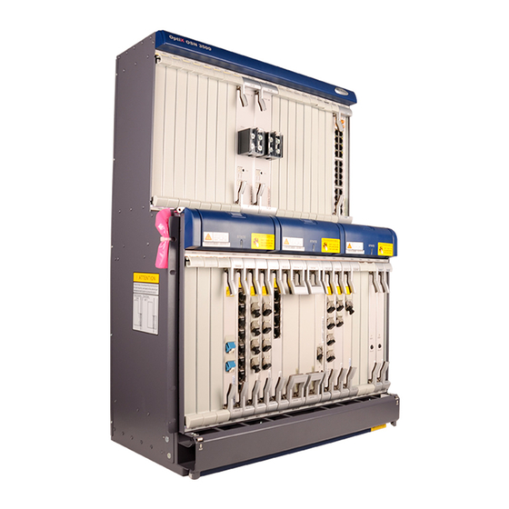
- Page 8 Introduction to the OptiX OSN 3500 Equipment Exterior of the OptiX OSN 3500 III Subrack Front View Bolt for the PGND cable Front view of the N1PIUB N1PIUB ESD jack Cable trough Air filter Side View Oblique View Label for the OptiX OSN 3500 III...
-
Page 9: Front View
N1PIU\N1PIUA NOTE The exterior of the enhanced OptiX OSN 3500 subrack (1100 W) is the same as that of the general OptiX OSN 3500 subrack. The N1PIU power board is used for the general OptiX OSN 3500 subrack, and the N1PIUA power board is used for the enhanced OptiX OSN 3500 subrack (1100 W). -
Page 10: Installing Components
Installing Components Positions of the Installation Holes • Front view of the cabinet • Positions of the installation holes Structural Position of the Remarks Component Installation Hole The fan and air filter are installed in the 11, 13, 20, and 22 OSN 3500 subrack. - Page 11 Installing the Subrack Holes for installing Holes for installing mounting ears of the mounting ears of the subrack in the N63E subrack in the T63 cabinet cabinet Ensure that the installation position of the mounting ears of the subrack matches the cabinet to be installed. Floating nut Installation hole Install the floating nuts.
- Page 12 Checking the Power Jumpers on the Board Checking Power Jumpers on the GSCC NOTE Check the power jumper settings and modify the settings as required. By default, the power jumpers are capped. • Position of the jumpers of the N1GSCC (layout 1) To set the input voltage of the equipment NOTE...
- Page 13 Checking the Power Jumpers on the Board NOTE Check the power jumper settings and modify the settings as required. By default, the power jumpers are capped. • Position of the jumpers of the N3GSCC (layout 1) Power module To set the input voltage of the equipment NOTE card...
- Page 14 Checking the Power Jumpers on the Board NOTE Check the power jumper settings and modify the settings as required. By default, the power jumpers are capped. • Position of the jumpers of the N4GSCC Power J3202 To set the input voltage of the module equipment J3201...
- Page 15 Checking Jumpers on the AUX NOTE Check the setting of the jumper J9. Modify the setting if required. By default, the jumper J9 is being capped. Set the jumper J9 as follows: To enable the subrack to work as the main subrack, cap the jumper J9. To enable the subrack to work as the extended subrack, do not cap the jumper J9.
- Page 16 Installing Cable Distribution Plates Phillips screwdriver NOTE A cable distribution plate is installed in a proper position above the subrack. Installing Fiber Management Trays Exterior of the Fiber Positions of the Installation Holes Management Tray Mounting ear Holes for installing mounting ears of the N63B cabinet Plate Holes for installing mounting ears of the T63 cabinet Fiber hole...
-
Page 17: Installation Method
Installation Method Phillips screwdriver 12±1.2 Kgf.cm 30±3 Kgf.cm >50 mm Install mounting ears on the fiber management tray. Secure the fiber management tray in the cabinet. NOTE By default, the fiber management tray is installed in the lower part of the cabinet and is more than 50 mm away from the subrack. - Page 18 Installing the SS61COA Connections Between Ports and Optical Fibers • Exterior of the SS61COA LC fiber connector Optical input port Optical output port RS232-2 port Monitoring Monitoring Power port RS232-1 port DIP switch port 1 port 2 NOTE RS-232-1 and RS-232-2 are management ports. MONITOR-1 and MONITOR-2 are alarm output ports. •...
- Page 19 Installation Procedure • Installation effectiveness Phillips screwdriver Flat-head screwdriver 30±3 Kgf.cm Cable tray 30±3 Kgf.cm Install the holder. Remove the cable tray. 30±3 Kgf.cm 30±3 Kgf.cm Install the cable tray. Install the SS61COA. NOTE When you install the SS61COA inside the cabinet, 125 mm of space is required. By default, the SS61COA is installed below the lower subrack and is more than 50 mm away from the subrack.
- Page 20 Cable Connections Serial port cable SS61COA SS61COA Power port of the SS61COA To the serial port of the SS61COA Power cable for the SS61COA Serial port cable...
- Page 21 Installing the SS62COA Connections Between Ports and Optical Fibers • Front view of the SS62COA LC fiber connector Transmit port (SC/PC) Receive port (E2000) Power input port RS-232-1 RS-232-2 • Fiber connections of the SS62COA Optical fiber Optical interface board Optical interface board SS61COA/ SS62COA...
- Page 22 Cable Connections To the serial port of the SS62COA Serial port cable To the power supply facilities in the telecommunications room Installation Procedure Phillips screwdriver 30±3 Kgf.cm 12±1.2 Kgf.cm Install the mounting ears. Secure the SS62COA on the columns. NOTE When you install the SS62COA inside the cabinet, 125 mm of space is required.
- Page 23 Installing RPC Frames Exterior of the RPC Frame NOTE The RPC frame is powered by the tributary power output terminal on the power cable terminal block on the top of the cabinet. Straight- through network cables are used for communications between the RPC board and the subrack.
- Page 24 Cable Connections • Cable connections of the OptiX OSN 3500 III subrack • Cable connections of the general and enhanced OptiX OSN 3500 subracks To the power supply facilities in the telecommunications room LINE LINE RS232-1 RS232-2 RS232-1 RS232-2 NOTE...
- Page 25 Installing the DCM DCM frame Mounting bracket Screw Installation holes of Installation holes of the mounting ears of the mounting ears of the subrack in the the subrack in the T63 cabinet N63E cabinet Fix the mounting ears on the DCM frame. Put DCMs on the frame and fix them with screws from below.
-
Page 26: Installing Batteries
Installing the UPM Power System NOTE For the method of installing the ETP4890 UPM Power System, see the ETP4890 User Manual. Installation Position Subrack ≥50 mm Power system (EPS75-4815AF) Installing Batteries To BAT- To BAT+ Upper- layer tray Lower- layer tray Connect four batteries in series and fix them on the lower-layer tray. - Page 27 Installing the EPS75-4815AF Power System in the ETSI Cabinet T o p T o p B o tto m B o tto m N63E cabinet T63 cabinet Determine the position of installing the power system Fix the two mounting ears on the power system by on the mount bar of the cabinet.
- Page 28 Installing and Routing Cables Cable Holes on the Top and at the Bottom of the N63E Cabinet Cable Holes on the Top of the N63E Cabinet Cable hole Cable hole Cable hole Cable hole 600 mm 155 mm 155 mm 62 mm 81 mm 188 mm...
- Page 29 When two 32 A power inputs are available in the telecommunications room, one cabinet can be configured with only one OptiX OSN 3500 III subrack. Ensure that the switches of the external power supply facilities are in the "OFF" position.
- Page 30 When four 32 A or two 63 A power inputs are available in the telecommunications room, one cabinet can be configured with two OptiX OSN 3500 III subracks, but the power consumption of each subrack must be less than 1100 W.
- Page 31 • Precautions for installing the DC power distribution box (TN51PDU) DANGER Do not install short-circuiting copper bars in the power output area of the DC power distribution box. Determine whether to install short-circuiting copper bars in the power input area only according to the onsite power supply.
- Page 32 •Installing and Routing Power Cables – DC Power Distribution Box (DPD63-8-8 PDU) DANGER Do not install short-circuiting copper bars in the power output areas. NOTE Determine whether short-circuiting copper bars need to be installed in the power input areas based on the site survey result.
- Page 33 •Installing Short-circuiting Copper Bars – DC Power Distribution Box (DPD63-8-8 PDU) DANGER Do not install the short-circuiting copper bar in the power output areas. NOTE Whether to install short-circuiting copper bars and horizontal short-circuiting copper plates in the power input area depends on the power supply in the equipment room.
- Page 34 •Installing and Routing Power Cables – DC Power Distribution Box (DPD100-2-8 PDU) DANGER Do not install short-circuiting copper bars in the power output areas. NOTE Before the equipment is delivered, 4-in-1 short-circuiting copper bars and 4-in-1 horizontal short-circuiting copper plates are installed in the power input area by default. Remove the front panel from the PDU before you install power cables and restore the front panel after you finish the installation.
- Page 35 Power cables for the subrack NOTE The maximum power consumption of the general OptiX OSN 3500 subrack is 720 W. Therefore, it is recommended that you select fuses that support a maximum current of 20 A for the power supply facility.
- Page 36 • Connections of the power cables between the general and enhanced OptiX OSN 3500 subracks and the DC power distribution box (TN51PDU) A-NEG(-) B-NEG(-) - 48 V - 48 V - 48 V - 48 V - 48 V - 48 V...
- Page 37 NOTE The maximum power consumption of the OptiX OSN 3500 III subrack is 2300 W. Therefore, it is recommended that you select fuses that support a maximum current of 63 A for the power supply facility.
- Page 38 "Assembling Cable Connectors" part. NOTE The maximum power consumption of the OptiX OSN 3500 III subrack is 2300 W. When the N1PDU is used, the power consumption of the subrack cannot be more than 1100 W. Therefore, it is recommended that you select fuses that support a maximum current of 32 A for the power supply facility.
- Page 39 • Connections of the power cables between the OptiX OSN 3500 III subrack and the DC power distribution box (DPD63-8-8 PDU) NOTE Power cable connections vary depending on the power sources in the equipment room. When the power source supplies two 63 A power inputs and two 125 A power inputs, DPD63-8-8 PDU is used to interface four main/backup power inputs.
- Page 40 • Connections of the power cables between the general and enhanced OptiX OSN 3500 subracks and the DC power distribution box ( DPD100-2-8 PDU) B-RTN1(+) A-RTN1(+) B-NEG1(-) A-NEG1(-) -48 V Power source in the equipment room -48 V Power source...
- Page 41 Installing and Routing Power Cables for the Subrack • Installing power cables for the N1PIU\N1PIUA Route the power cables for the subrack through Connect the power cables for the subrack to the the cable distribution plate to the PIU board. PIU board.
- Page 42 Installing and Routing Power Cables and PGND Cables - Overhead Cabling • Installing and Routing Power Cables and PGND Cables – Overhead Cabling (TN51PDU) DANGER Phillips screwdriver Do not install or remove power cables when the power is on. To avoid human injuries, power off the cabinet before performing the operations.
- Page 43 •Installing and Routing Power Cables and PGND Cables – Overhead Cabling (DPD63-8-8 PDU) CAUTION Do not install or remove power cables while the equipment is powered on. Ensure that the power is switched off prior to removing or installing a power cable to avoid bodily injuries. Adjustable wrench Phillips screwdriver NOTE...
- Page 44 •Installing and Routing Power Cables and PGND Cables – Overhead Cabling (DPD100-2-8 PDU) CAUTION Do not install or remove power cables while the equipment is powered on. Ensure that the power is switched off prior to removing or installing a power cable to avoid bodily injuries. Adjustable wrench Phillips screwdriver NOTE...
- Page 45 Installing and Routing Power Cables and PGND Cables - Underfloor Cabling • Installing and Routing Power Cables and PGND Cables – Underfloor Cabling (TN51PDU) Diagonal pliers Phillips screwdriver Adjustable wrench CAUTION Install OT terminals correctly according to the wiring terminal labels on the plastic cover of the DC power distribution box.
- Page 46 • Installing and Routing Power Cables and PGND Cables – Underfloor Cabling (DPD63-8-8 PDU) CAUTION Do not install or remove power cables while the equipment is powered on. Ensure that the power is switched off prior to removing or installing a power cable to avoid bodily injuries. Ground cable M8 screw (yellow-green)
- Page 47 • Installing and Routing Power Cables and PGND Cables – Underfloor Cabling (DPD100-2-8 PDU) CAUTION Do not install or remove power cables while the equipment is powered on. Ensure that the power is switched off prior to removing or installing a power cable to avoid bodily injuries. Ground cable M8 screw (yellow-green)
- Page 48 Installing and Routing Cabinet Indicator Cables Indicator Ports of the Cabinet CAUTION Do not connect other cables to the indicator Pin No. Signal Designation ports or indicator Positive critical alarm signals cascading ports of the cabinet. Negative critical alarm signals Indicator ports of Ensure that no metallic the cabinet...
-
Page 49: Alarm Ports
Installing and Routing Alarm Cables Alarm Ports Alarm output ports (ALMO1 and ALMO2) Pin Signal Designation Pin Signal Designation Positive critical and major alarm outputs Reserved Negative minor and warning alarm Negative critical and major alarm outputs outputs Reserved Positive minor and warning alarm outputs Reserved Reserved Alarm input ports (ALMI1-ALMI4) - Page 50 Installing and Routing E1/T1 Cables E1/T1 Ports E 1 / T 1 interface board ( D 75 S , D 12 S , D 12 B ) NOTE The exterior, pin assignment, and installation method of the T1 cables are the same as those of the 120-ohm E1 cables. Pin 44 NOTE Related wiring tables are delivered with the specific cables.
- Page 51 1 2 3 NOTE When the 16-wire E1 cables are used, bind the Connect the E1 cables to the ports on the interface cables for three layers on the side panel of the board, and then fasten the captive screws of each cabinet.
- Page 52 Underfloor Cabling • Routing E1 cables for the upper subrack Route the E1 cables into the cabinet through the Route the E1 cables for the upper subrack upwards along the side panel of the cabinet to the cable cable holes at the bottom of the cabinet. distribution plate of the upper subrack, and then route the E1 cables through the cable distribution plate.
- Page 53 Connect the E1 cables to the ports on the interface board, and then fasten the captive screws of each DB44 connector. 1 2 3 NOTE When the 16-wire E1 cables are used, bind the cables for three layers on the side panel of the cabinet.
- Page 54 • Routing E3/T3/E4/STM-1 cables for the lower subrack Guide rail Route the cables into the cabinet Route the cables downwards along Route the cables through the cable through the cable holes on the top the side panel of the cabinet to the distribution plate, and then connect of the cabinet.
- Page 55 Route the E3/T3/E4/STM-1 cables for the lower Connect the cables to the SMB ports on the interface subrack upwards along the side of the cabinet to the board from the upper part to the lower part. cable distribution plate above the lower subrack. NOTE The description uses cable routing on the right side as an example.
- Page 56 • Route Ethernet cables for the lower subrack Guide rail Route the Ethernet cables into Route the cables for the lower Route the cables through the cable the cabinet through the cable subrack downwards along the side distribution plate, and then connect holes on the top of the cabinet.
- Page 57 Route the cables for the lower subrack upwards along Route the cables through the cable distribution plate, and the side panel of the cabinet to the cable distribution then connect them to the RJ45 ports on the Ethernet plate above the lower subrack. board from the upper part to the lower part.
- Page 58 • Precautions for handling the toggle lever switch •Turning on the switch O: OFF I: ON Pull the switch out gently. Turn the switch. Release the switch. •Turning off the switch Pull the switch out gently. Turn the switch. Release the switch. •...
- Page 59 Installing and Routing IF Jumpers IF cable Attach temporary labels to both ends of the IF jumper. Route the IF jumper through the cable hole outside the cabinet to the IF interface board. Moment: 0.8~1.1 N· M Connect the TNC connector of the IF jumper to the IF port of the IF interface board and reserve a proper length of IF jumper.
- Page 60 To the PDU room NOTE The DC power distribution box provides only four current inputs. If two OptiX OSN 3500 III subracks are installed in a cabinet, the RPWR board must gain access to the power supply facilities in the telecommunications room.
- Page 61 Installing and Routing External Clock Cables Clock Ports 75-ohm clock output 1 75-ohm clock output 2 75-ohm clock input 1 75-ohm clock input 2 120-ohm clock input/output 1 120-ohm clock input/output 2 NOTE Select appropriate clock cables according to the type of the clock port on the opposite equipment.
- Page 62 Underfloor Cabling Route the clock cables into the cabinet through the Route the clock cables upwards along the side panel cable holes at the bottom of the cabinet. of the cabinet to the cable distribution plate. Route the clock cables through the cable distribution Trim the clock cables and bind them onto the binding plate and connect them to the clock ports on the AUX plate.
- Page 63 Installing and Routing SDI Coaxial Cables Ports on the VST4 Board OUT1 OUT2 OUT3 OUT4 Ports on the Type of Port Application Front Panel IN1-IN4 SMB (which can be converted to BNC Receives electrical signals of the DVB- through a conversion cable) ASI, SD-SDI, or HD-SDI service.
- Page 64 NOTE This section describes how to install and route cables for PCM boards in an OptiX OSN 3500 subrack with 14 PCM boards (seven on the right and seven on the left), one system control board, and one line board.
- Page 65 Installing and Routing Cables for the Extended Subrack EXA EXA EXB EXB Main subrack Cables for the extended subrack Extended subrack Crossover cable EXA EXA NOTE EXB EXB A J9 jumper is available at the right lower corner of the AUX board.
- Page 66 The corrugated tube needs to be routed into the cabinet for approximately 10 cm. When routing and installing fibers onsite, you need to clean fiber end faces. For detailed operations, see the multimedia at the following website: http://support.huawei.com/carrier/docview!docview?nid=DOC1000132657 Underfloor Cabling Route the fiber patch cords through a corrugated tube.
- Page 67 When routing and installing fibers onsite, you need to clean fiber end faces. For detailed operations, see the multimedia at the following website: http://support.huawei.com/carrier/docview!docview?nid=DOC1000132657 Installing and Routing Internal Optical Fibers Connections Between Internal Optical Fibers •...
- Page 68 • Fiber connections between the SL16 and the COA • Fiber connections between the SF64 and the RPC RPC01 RPC02 SF64 SL16 SL16 OUT1 BOUT LINE LINE OUT2 POUT SF64 OUT1 POUT BOUT OUT2 LINE LINE RPC01 RPC02 OptiX OSN equipment A OptiX OSN equipment B OptiX OSN equipment A OptiX OSN equipment B...
- Page 69 Installing Orderwire Phones Assembling the Orderwire Phone Base Installing the Orderwire Phone 30±3 Kgf.cm NOTE Set the ring switch to "ON" and the dial switch to "T". When installing an orderwire phone, tilt it upwards to avoid falloff.
-
Page 70: Checking The Installation
Checking the Installation Checking Installation Effectiveness What to Check For Method The cabinet is installed in the position specified in the engineering design documents. Check the position. The mechanical parts of the cabinet are installed correctly and securely, and are not Check. - Page 71 720 W (general subrack) 20 A OptiX OSN 3500 1100 W (enhanced subrack (1100W) 32 A OptiX OSN 3500 III 2300 W 63 A Measure the voltage between NEG(-) and RTN(+) on the DC power distribution box. –48 V Power Supply –60 V Power Supply...
- Page 72 Checking Optical Fiber Attenuation CAUTION Do not expose your eyes to the laser when checking optical fiber attenuation. External optical fiber cable Short optical fiber jumper Optical fiber to be checked Optical power P1 Optical power P2 Optical power meter Stable optical generator Measure the output optical power of the optical generator Measure the output optical power of the optical generator.
- Page 73 Engineering Labels Attaching Labels Attaching Labels to Power Cables NOTE As a general rule, attach the labels to the cables 2 cm away from the connectors. Attach the identification label to Identification label the right side of the cable when cabling is done vertically.
- Page 74 MN: cabinet number Labels for A01-03-10-05: indicates that one end of the network B: subrack number network cables cable is connected to Huawei equipment, specifically, MN-Z C: physical slot to network port 5 in slot 10 of subrack 03 in the number...
- Page 75 Name Content Example Remarks MN: cabinet number B: subrack number C: physical slot number A01-01-05-05-R: indicates that the local D: network port number Labels for end of the optical fiber is connected to R: optical receiver port optical fibers optical receive port 05 in slot 05 of T: optical transmitter port between two subrack 01 in the cabinet in row A and...
- Page 76 Name Content Example Remarks G01 01 MN: cabinet number B: subrack number Engineering C: physical slot number labels for the MN-B-C-D-R/T D: cable number trunk cables G01-01-05-12-T: indicates that the R: optical receive port between two local end of the trunk cable is T: optical transmit port pieces of connected to the optical transmit...
- Page 77 When stripping the insulation layer of a power cable, do not damage the metallic conductor of the power cable. If the bare crimp terminal is not provided by Huawei, change the value of L1 according to the actual value L of the bare crimp terminal.
- Page 78 Crimp the joint parts of the bare crimp terminal and Push the heat shrink tubing A towards the connector the conductor of the power cable using a crimping tool. until the heat shrink tubing covers the crimped parts of the bare crimp terminal and the conductor of the power cable.
- Page 79 • Installation procedure Strip a part of the insulation layer B of the power Route the conductor of the power cable into the cord cable according to the cross-sectional area of the end terminal A, and then align the conductor with the conductor, and ensure that the conductor C of the edge of the cord end terminal.
- Page 80 HUAWEI TECHNOLOGIES CO., LTD. Huawei Industrial Base Bantian Longgang Shenzhen 518129 People's Republic of China www.huawei.com...