Huawei OptiX OSN 3500 Routine Maintenance
Optical network curriculum development section
Hide thumbs
Also See for OptiX OSN 3500:
- Quick installation manual (81 pages) ,
- Quick installation manual (48 pages)

Related Manuals for Huawei OptiX OSN 3500


Summary of Contents for Huawei OptiX OSN 3500
- Page 1 OptiX OSN 3500/2500/1500 Routine Maintenance ISSUE Optical Network Curriculum Development Section...
- Page 2 Course Objectives operation environment Master of OptiX Equipment Understand the maintenance items of OptiX Equipment Master the basic maintenance operations of OptiX Equipment Be able to perform the routine maintenance of OptiX Equipment ...
- Page 3 Contents Part 1 Operation Environment Part 2 Daily Maintenance Items Part 3 Basic Operations and Precautions Part 4 Equipment Running and Routine Maintenance...
- Page 4 Contents Part 1 Operation Environment Operation Environment of equipment Operation Environment of NMS Part 2 Daily Maintenance Items Part 3 Basic Operations and Precautions Part 4 Equipment Running and Routine Maintenance...
- Page 5 Running Environment of Equipment Power Supply: Ensure the DC voltage for OptiX transmission equipment is -48V/-60V Tolerance range: -48V/-60V ± 20%=-38.4V~ -72V Grounding of equipment: Combined grounding, resistance<1 Ohm ...
- Page 6 Running Environment of Equipment Temperature and humidity requirements Operating Temperature Relative humidity (%) conditions (°C) Long-term operating 0°C~40°C 10%~90% conditions Short-term working -5°C~55°C 5%~95% condition Better conditions 20°C...
- Page 7 Running Environment of Equipment Good ventilation to keep the fans running normally Clean the fan screen regularly(once or twice per month) Don’t put unrelated goods at the ventilation opening(tail fibers, 2M trunck cables, for example) Check board overheat, good wind flow at the ventilation opening Monitor the rack temperature in NMS.
- Page 8 Running Environment of the NMS computer Prepare a smooth, stable and sizable computer desk for placing the computer Keep ventilation and avoid direct sunshine, heat source, humidity, smoke and dust Configure UPS be away from other electronic equipments ...
- Page 9 Contents Part 1 Operation Environment Part 2 Daily Maintenance Items Part 3 Basic Operations and Precautions Part 4 Equipment Running and Routine Maintenance...
- Page 10 OptiX Equipment Daily Maintenance Items 1. Keep equipment room clean, avoid moisture and mice. 2. Act as per “SDH Daily Maintenance Proposal” carefully, and keep a record.
- Page 11 OptiX Equipment Daily Maintenance Items 3. Clean the fan screen every two weeks. Fan must be on all the time. 4. Avoid man-made mistakes as possible as you can.
- Page 12 OptiX Equipment Daily Maintenance Items 5. Always wear anti-ESD wrist strip. 6. Be careful about fiber and cable adjustment. NEVER forget to mark them before adjustment.
- Page 13 OptiX Equipment Daily Maintenance Items 7. Check the transmission lines regularly. Test the working and/or protection fibers yearly if possible. 8. Keep the passwords in a secure place and modify it regularly, esp. superuser or administrator password.
- Page 14 OptiX Equipment Daily Maintenance Items 9. Kill virus regularly. 10. UPS power supply should be equipped. Back up the computer regularly. 11. Unclear alarms should be checked thoroughly. In case of need, contact Huawei Office ASAP.
- Page 15 Contents Part 1 Operation Environment Part 2 Daily Maintenance Items Part 3 Basic Operations and Precautions Precautions of Maintenance Operations Basic Operation of the Maintenance Part 4 Equipment Running and Routine Maintenance...
- Page 16 Precautions of Maintenance Operations Precautions for Laser Safety The unused optical interface and optical connector should be covered with optical caps Cleaning the optical interface and fiber jumper connector Precautions for the loop back operation of the optical interface board:using attenuator Precautions for replacement of optical interface board:pull off the optical fiber from the circuit board first...
- Page 17 Precautions of Maintenance Operations Precautions for Electrical Safety Anti-static precautions:wear the grounded ESD wrist strap Precautions for board electrical safety:in the ESD bag and the grounded ESD wrist strap Precautions for power supply maintenance Never install or remove the equipment with the power on ①...
- Page 18 Precautions of Maintenance Operations Precautions for Board Mechanical Safety Avoid shocks during the transportation plug in/pull out the board with care, and strictly follow procedures. Precautions for Network Management System Maintenance Do not quit the network management system It is strictly forbidden to run irrelevant programs,especially games.
- Page 19 Basic Operation of Maintenance Operations Clean the Fan Plugging/Unplugging Tail Fiber Plugging/Unplugging Board Switch On/Off the Equipment Cut Off the Alarm Sound Resetting SCC Operations of the Loopback Test of Bit Errors Fiber/Cable Tag Description ...
- Page 20 Clean the air filter of the Fan Clean the air filter once every two weeks. Procedures : Pull out the filter peel off the sponge stuck on the filter clean it with water dry it in a ventilated place(Never insert any wet air filter into the equipment) stick the sponge again on the air filter insert the filter by gently pushing the air filter along...
- Page 21 Plugging/Unplugging Tail Fiber LC/PC fiber jumper SC/PC fiber jumper Two kinds of optical interfaces:SC/PC and LC/PC Plug/unplug SC/PC:use special tool (such as fiber extractor) Plug/unplug LC/PC:in the axial direction without rotation...
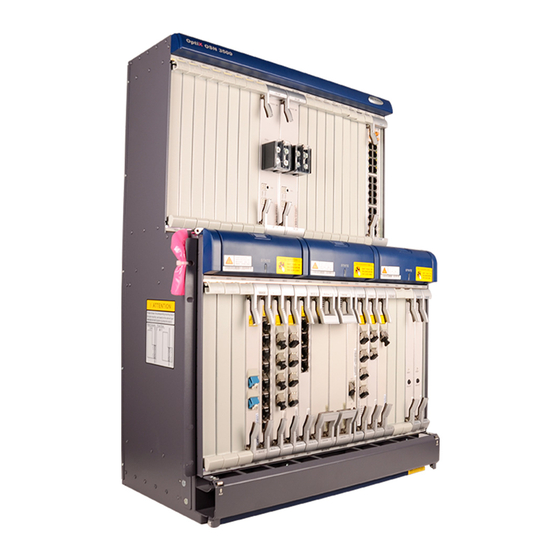
- Page 22 Plugging in/Pulling out and Replacing Board Names of each part 1. Service processing board (such as PQ1) 2. Service interface 3. Optical interface board (such as board (such as D75S) SL16) 4. STM-1/4/16 system control, cross-connect, optical interface board 5.
- Page 23 Plugging in/Pulling out and Replacing Board Method of plugging in a board Slot correct? Wear an grounded ESD wrist pinch the ejector levers and turn them sideward Insert the board smoothly along the guide rail until cannot go any further Turn the ejector levers inward with force ...
- Page 24 Plugging in/Pulling out and Replacing Board Method of plugging in a board From right to left Align all boards Check the pins on motherboard No forced plugging ...
- Page 25 Plugging in/Pulling out and Replacing Board Method of pulling out a board Loosen the screws pull the upper and lower ejector levers simultaneously The subrack beam acts as the fulcrum Removal of blank filler panel Pull the board smoothly along ...
- Page 26 Plugging in/Pulling out and Replacing Board Make sure the board to be replaced and the replacement board are the same model, e.g., SSN2SL16A04 Boards with the same name can be inserted in all equipments Board type ID “SSN2SL16A04 ” Handle bar Board...
- Page 27 Plugging in/Pulling out and Replacing Board Replacing SCC board On SCC, there are NE ID, nesoft, configuration data, so pay SPECIAL attention: After replacement, configure the ID again After replacement, resend the configuration data to NE ...
- Page 28 Equipment Power On/Off Sequence of equipment power on Hardware is installed correctly No short circuit Power is OK Subrack power on: Turn on the air switch for subrack ...
- Page 29 Equipment Power On/Off Sequence of equipment power off If power off,the services will be broken Subrack power off: Turn off the air switch ...
- Page 30 Alarm Muting There are two ways to mute alarm: 1 the ALC switch on SCC/CXL1/4/16 board Short Long Attention: better leave ALC upward 2 the Alarm Mute switch (MUTE): OFF---the audio alarm will be closed thoroughly; ON---the audio alarm will be reported.
- Page 31 Resetting SCC Board Two methods: Push RST button on SCC By means of T2000 Resetting SCC is dangerous...
- Page 32 Loopback Operation Type of loopback Software loopback: set via NMS; Hardware loopback: set using tail fiber and self-loop cable manually. Inloop: route signals from XC back to XC; Outloop: route signals away from XC back to interface port. ...
- Page 33 Loopback of SDH interface Hardware Loopback of SDH interface Self-loop Cross loop Handle bar Attenuator!!! ...
- Page 34 Loopback of SDH interface Software loopback of SDH interface the VC4 loopback or Optical interface loopback setup in NMS, which is divided into inloop and outloop evenly. SDH NE equipment Inloop Line Line Inloop Outloop Outloop Tributary Tributary Tributary...
- Page 35 Loopback of PDH interface Hardware loopback of PDH interface Hardware loopback is generally inloop Two positions: wiring area of subrack and DDF Software loopback of PDH interface The software loopback of PDH interface means to set outloop or ...
- Page 36 Loopback of PDH interface Hardware loopback of PDH interface Hardware loopback is generally inloop Two positions: wiring area of subrack and DDF Software loopback of PDH interface The software loopback of PDH interface means to set outloop or ...
- Page 37 Test of Bit Errors On-line test method 1. select a traffic channel 2. find the port on the DDF corresponding to this channel 3. Connect one end of the test cable with the on-line test connector of the port on the DDF and the other end with the on-line test interface of the BER tester 4.
- Page 38 Test of Bit Errors Off-line test method 1. select a traffic channel (E1, E3, T3, E4 or STM-1) 2. Connect the TX and RX ports of BER tester with the RX and TX PDH/SDH interfaces of this equipment respectively 3.
- Page 39 Fiber and cable tag Information carried on the label for fiber connecting equipments Description Example Content of Tag MN-B-C-D-R/T MN: SERIAL For example: A01. NUMBER OF THE CABINET B: serial number of Numbered in top-down order with two digits, for example, the subrack C: physical slot Numbered in top-down and left-right order with two digits,...
- Page 40 Fiber and cable tag Information carried on the label for fiber connecting equipments Description Example Content of Tag MN-B-C-D-R/T MN: SERIAL The meanings are the same as above. When the local NUMBER OF THE device and the opposite end device are not in the same CABINET equipment room, MN can be presented by the name of the equipment room.
- Page 41 Making Network Cable Standard cable v.s. Crossover cable Crossover UTP cable Standard UTP cable...
- Page 42 Contents Part 1 Operation Environment Part 2 Daily Maintenance Items Part 3 Basic Operations and Precautions Precautions of Maintenance Operations Basic Operation of the Maintenance Part 4 Equipment Running and Routine Maintenance Routine Maintenance Items of Equipment Routine Maintenance Items through NM...
- Page 43 Routine Maintenance Items of Equipment Routine Maintenance Items of Equipment Check the Audio Alarm of the Equipment Observe Indicators on Cabinet and Subrack Observe the Indicator of the Board Check Equipment Temperature Check and Clean Fan Periodically Check Orderwire Check Service----Error Test...
- Page 44 Routine Maintenance Items through NM Routine Maintenance Items through NM Start/shut down the OptiX iManager network management system Periodically change the login password of the NM user Log in to the NM as a lower-level user Check the NE and board status Check the alarms Monitor the performance events Check the protection switching...
- Page 45 Contents Part 1 Operation Environment Part 2 Daily Maintenance Items Part 3 Basic Operations and Precautions Part 4 Equipment Running and Routine Maintenance...