Advertisement
Table of Contents
- 1 Installation Flow
- 2 Tools for Installation
- 3 Installing Components
- 4 Installing the Subrack
- 5 Installation Method
- 6 Installation Procedure
- 7 Cable Connections
- 8 Installation Position
- 9 Installing Batteries
- 10 Connection and Installation
- 11 Alarm Interface
- 12 Checking the Installation
- 13 Engineering Labels
- 14 Attaching Labels
- Download this manual
Advertisement
Table of Contents

Related Manuals for Huawei OptiX OSN 2500


Summary of Contents for Huawei OptiX OSN 2500
- Page 1 OptiX OSN 2500 Quick Installation Guide Issue: 12 Date: 2017-09-30 HUAWEI TECHNOLOGIES CO., LTD.
- Page 2 Notice The purchased products, services and features are stipulated by the contract made between Huawei and the customer. All or part of the products, services and features described in this document may not be within the purchase scope or the usage scope. Unless otherwise specified in the contract, all statements, information, and recommendations in this document are provided "AS IS"...
-
Page 3: Installation Flow
Installation Flow Start Positions of the Page 6 Installation Holes Before You Start Page 1 Precautions Installing the Page 7 Subrack Tools for Checking the Page 2 Installation Page 8 Power Jumpers on the Board Installing Fiber Page 9 Management Page 3 Cables to 10... - Page 4 Precautions This document provides quick guidelines for hardware installation. This document does not describe pre-delivery assembly. This document describes only procedures for onsite installation. Electrostatic Discharge Wear ESD gloves or an ESD wrist strap prior to contact with the equipment or before handling the plug-boards, boards, and IC chips to prevent damage to sensitive components caused by electrostatic discharge from the human body.
-
Page 5: Tools For Installation
Tools for Installation Long measuring tape Phillips screwdriver Flat-head screwdriver Adjustable wrench Heat gun Utility knife COAX crimping tool Wire clippers Wire stripper COAX stripper RJ45 crimping tool Diagonal pliers Cold press pliers Network cable tester Multimeter... - Page 6 Cables –48 V DC power cable BGND power cable PGND cable Power cable for the general 75-ohm 8xE1 cable 120-ohm 8xE1 cable subrack 75/120-ohm clock transit cable (1) 75/120-ohm clock transit cable (2) 75-ohm clock cable Alarm output and input cable Alarm cascading cable between subracks COA cascading serial port cable COA serial port cable...
- Page 7 Boards are fragile and valuable. When handling or placing a board, exercise caution and put it into a dedicated packing box. Coherent boards, such as TN12LSC, TN11LTX, TN15LSXL, and TN55NS3, must be packed with original packaging materials during transportation. If the original packaging materials are lost, contact Huawei.
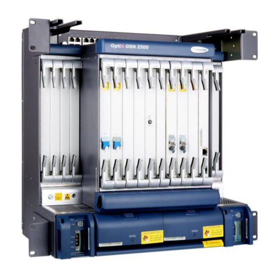
- Page 8 Introduction to the OptiX OSN 2500 Equipment Exterior of the OptiX OSN 2500 Subrack Front View Bolt for the PGND cable ESD jack Cable trough Air filter Oblique View...
-
Page 9: Installing Components
Installing Components Positions of the Installation Holes Front view of the cabinet Positions of the installation holes Structural Position of the component Installation Hole 8, 10, 24 and 26 Lower OSN 2500 subrack 31, 33, 47 and 49 Middle OSN 2500 subrack 54, 56, 70 and 72 Upper OSN 2500 subrack 78 and 82... -
Page 10: Installing The Subrack
Installing the Subrack Holes for installing Holes for installing mounting ears of the mounting ears of the subrack in the N63E subrack in the T63 cabinet cabinet Ensure that the installation position of the mounting ears of the subrack matches the cabinet to be installed. Floating nut Installation hole Install the floating nuts. - Page 11 Checking the Power Jumpers on the Board NOTE Check the power jumper settings and modify the settings as required. By default, the power jumpers are capped. • Position of the jumpers of the SAP Power module To set the input voltage of the equipment NOTE When the jumpers are not capped, the equipment is supplied with the –60 V power.
-
Page 12: Installation Method
Installing Fiber Management Trays Positions of the Installation Holes Exterior of the Fiber Management Tray Mounting ear Holes for installing mounting ears of the N63B cabinet Plate Holes for installing mounting ears of the T63 cabinet Holes for installing mounting ears of the N63E cabinet Fiber hole Installation Method Phillips screwdriver... - Page 13 Spooling Fibers in the Fiber Management Tray With no attenuator used (the optical fibers connected to the optical interface board are on the same side of the cross- connect and timing board) With no attenuator used (the optical fibers connected to the optical interface board are on different sides of the cross- connect and timing board) Variable optical attenuator...
- Page 14 Installing the SS61COA Connections Between Ports and Optical Fibers Exterior of the SS61COA LC fiber connector Optical input port Optical output port DIP switch Monitoring Power port Monitoring RS232-1 RS232-2 port 1 port 2 port port RS-232-1 and RS-232-2 are management ports. MONITOR-1 and MONITOR-2 are alarm output ports. Fiber connections of the SS61COA Optical fiber 10 dB fixed...
-
Page 15: Installation Procedure
Installation Procedure Installation effectiveness Phillips screwdriver Flat-head screwdriver Cable tray Install the holder. Remove the cable tray. Install the cable tray. Install the SS61COA. When you install the SS61COA inside the cabinet, 125 mm of space is required. By default, the SS61COA is installed below the lower subrack and is more than 50 mm away from the subrack. -
Page 16: Cable Connections
Cable Connections F&f cable COA power interface COA power cable COA power cable Serial port cable MONITOR-1 and MONITOR-2 are the alarm output interfaces that are separately used in the SS61COA. They are not used, however, if the SS61COA has been connected to the subrack. Connect the SS61COA to the alarm devices in the equipment room as required. - Page 17 Installing the SS62COA Connections Between Ports and Optical Fibers Front view of the SS62COA LC fiber connector Transmit port (SC/PC) Receive port (E2000) Power input port RS-232-1 RS-232-2 Fiber connections of the SS62COA Optical Optical fiber Optical interface board interface board SS62COA SS61COA/ BA/BPA...
- Page 18 Installation Procedure Phillips screwdriver Secure the two mounting ears to the SS62COA chassis. Secure the SS62COA into the cabinet. To install the SS62COA inside the cabinet, you need to provide a space with 125 mm in height. By default, the SS62COA is installed at the bottom of the cabinet (first and third floating nuts).
- Page 19 Cable Connections COA power interface COA power cable F&f cable...
- Page 20 Installing the RPC Frame Exterior of the RPC Frame The RPC frame is powered by the tributary power output terminal on the power cable terminal block on the top of the cabinet. Straight- through network cables are used for the communication between the Power module RPC board and the subrack.
- Page 21 Cable Connections Power cables of the RPC frame Insert the RJ-45 connector at one end of the network cable in an idle interface of the HUB. Insert the RJ-45 connect at the other end of the network cable in the LAN interface on the RPC board. Insert the RJ-45 connector at one end of the network cable in an idle interface of the HUB.
- Page 22 Installing the DCM DCM frame Mounting bracket Screw Installation holes of Installation holes of the mounting ears of the mounting ears of the subrack in the the subrack in the T63 cabinet N63E cabinet Fix the mounting ears on the DCM frame. Put DCMs on the frame and fix them with screws from below.
-
Page 23: Installation Position
Installing the UPM Power System NOTE For the method of installing the ETP4830 UPM Power System, see the ETP4830 User Manual. Installation Position Subrack ≥50 mm Power system (EPS75-4815AF) Installing Batteries To BAT- To BAT+ Upper- layer tray Lower- layer tray Connect four batteries in series and fix them on the lower-layer tray. - Page 24 Installing the EPS75-4815AF Power System in the ETSI Cabinet T o p T o p B o tto m B o tto m N63E cabinet T63 cabinet Determine the position of installing the power system Fix the two mounting ears on the power system by on the mount bar of the cabinet.
- Page 25 Installing and Routing Cables Cable Holes on the Top and at the Bottom of the N63E Cabinet Cable Holes on the Top of the N63E Cabinet Cable hole Cable hole Cable hole Cable hole 600 mm 155 mm 155 mm 62 mm 81 mm 188 mm...
- Page 26 Installing and Routing Power Cables and PGND Cables Connections Between Power Cables •Connections between power cables (N1PDU) Internal PGND cable PGND cable - 48 V - 48 V Office ground Office power supply Subrack power cable connector PGND cable Power cables are classified into cabinet power cables and subrack power cables.
- Page 27 •Connections between power cables (DPD100-2-8 PDU) B-RTN1(+) A-RTN1(+) B-NEG1(-) A-NEG1(-) -48 V -48 V Office ground PGND cable Power cables for the subrack DPD100-2-8 PDU Ground Point Power cables are classified into cabinet power cables and subrack power cables. The subrack power cables are connected to the power distribution unit and are bound to the rear column before delivery.
- Page 28 Power Cables and PGND Cables -- Upward Cabling •Power Cables and PGND Cables -- Upward Cabling (N1PDU) Do not install or demount the power cable while the power is on. To avoid personal Phillips screwdriver injuries, turn off the corresponding power before performing the operations. A torque spanner is required to fasten external power cables.
- Page 29 •Power Cables and PGND Cables -- Upward Cabling (DPD100-2-8 PDU) CAUTION Do not install or remove power cables while the equipment is powered on. Ensure that the power is switched off prior to removing or installing a power cable to avoid bodily injuries. Adjustable wrench Phillips screwdriver NOTE...
- Page 30 Power Cables and PGND Cables -- Downward cabling • Power Cables and PGND Cables -- Downward cabling (N1PDU) Phillips screwdriver Install OT terminals correctly according to the wiring terminal labels on the plastic Adjustable wrench cover of the DC power distribution box. Connect the power cable and PGND cable in the similar way for upward cabling.
- Page 31 • Power Cables and PGND Cables -- Downward cabling (DPD100-2-8 PDU) CAUTION Do not install or remove power cables while the equipment is powered on. Ensure that the power is switched off prior to removing or installing a power cable to avoid bodily injuries. Ground cable M8 screw (yellow-green)
- Page 32 Installing and Routing the Power Cables -- Testing Resistance Between Power Cable Poles Ensure that the switch of the external power supply device is turned to the ‘OFF’ side. If a power monitoring device is installed to the power supply device, disconnect the power supply device and the power monitoring device before the test.
-
Page 33: Connection And Installation
Installing and Routing the Cabinet Indicator Cables Connection and Installation Cabinet indicator concatenation cable To the lower subrack To the upper subrack To the cabinet indicators (Black) Connect the cabinet indicator cable between the cabinet indicators and the "LAMP1" interface on the SEI board of the lower subrack. -
Page 34: Alarm Interface
Installing and Routing the Alarm Cables Alarm Interface Alarm output interface(ALMO1) and alarm output concatenating interface(ALMO2) Funciton Funciton The positive of critical and Reserved major alarm output The negative of cirtical and The negative of major and major alarm output warning alarm output The positivie of minor and Reserved... - Page 35 Connection of the Alarm Cable Alarm output and input cable To alarm monitor Alarm Alarm concatenation concatenation cable between cable between subracks subracks Cabinet 2 Cabinet 1 When any critical alarms or major alarms occur in one of subracks, the indicators on the alarm monitor become...
- Page 36 Upward Cabling To the alarm monitor Cable distribution plate SEI board...
- Page 37 Downward cabling Cable distribution plate SEI board To the alarm monitor...
- Page 38 E1/T1 Cables and E1/T1 Interface E1/T1 interface 75-ohm 8xE1 cable E1/T1 interface board(D75S,D12S,D12B) 120-ohm 8xE1 cable Pin 44 Pin 1 The T1 cables have the same outer view, pin assignment, and installation procedure as the 120-ohm E1 cables. The printed pin assignment table of the E1 cable is attached in the package. Do not discard it before installation. You can connect the DDF to the D75S board by using the 75-ohm E1 cable only, to the D12S board by using the 120-ohm E1 cable only, and to the D12B board by using the 120-ohm or 75-ohm E1 cable.
- Page 39 Procedure for Upward Cabling Routing E1 cables at the cabinet side Routing E1 cables into the cabinet E1 cables for the upper subrack E1 cables for the lower subrack Route the E1 cables into the cabinet through the cabling holes on the top of the cabinet. Downward route the E1 cables of the upper subrack from the middle cabling holes on the top of the cabinet to the cable distribution plate above the upper subrack.
- Page 40 Downward Cabling Cable distribution plate Cabling on the left side is taken as an example in the description below, and that on the right side is the same. Do not route the left E1 cables to the right side of the cabinet, or conversely. In the case of downward cabling, lead the cables for the upper and lower subracks out from the side walls of the cabinet.
- Page 41 Installing and Routing the E3/T3/E4/STM-1 Cables Upward Cabling To the DDF of the equipment room The cables for the upper subrack The cables for the middle subrack The cables for the lower subrack Cable hole Cable distribution plate Cabling on the left side is taken as an example in the description below, and that on the right side is the same.
- Page 42 Downward cabling The cables for the lower subrack The cables for the middle subrack The cables for the upper subrack To the DDF of the equipment room Cabling on the left side is taken as an example in the description below, and that on the right side is the same.
- Page 43 Installing and Routing the Ethernet Cables Upward Cabling Cables for the upper subrack Cable hole Cables for the lower subrack Cables for the middle subrack Cabling on the left side is taken as an example in the description below, and that on the right side is the same.
- Page 44 Downward Cabling Cable distribution plate Cables for the upper subrack Cables for the middle subrack Cables for the lower subrack Cabling on the left side is taken as an example in the description below, and that on the right side is the same.
- Page 45 Installing and Routing the IF Cables Interface of Boards -48V power input interface 6-port 48V power output interface IF port ODU power switch Power input interface...
- Page 46 Connection of IF Cables RPWR FSD1 Subrack power cables, Connected to the 20A power. IF jumpers, which are connected to the IF cables. When the RPWR boards and the FSD1 boards are installed on the lower subrack, the method of connecting the cables is similar to the method of connecting the cables when RPWR boards and the IF boards are installed on the upper subrack.
- Page 47 Installing and Routing the External Clock Cables From 2M bit/s(Hz) BITS To the other equipment CLK1:120 ohm clock 1 CLK2:120 ohm clock 2 SEI board CLKO1:75 ohm clock output 1 CLKO2:75 ohm clock output 2 CLKI1:75 ohm clock input 1 CLKI2:75 ohm clock input 2 Select a correct clock cable according to the type of the clock interface on the opposite equipment.
- Page 48 Installing and Routing the Network Management Cable Network management system Network management cable Connect the network management cable only for the gateway NE. Route the network management cable in the similar way to route the external clock cable.
- Page 49 When routing fibers, take proper measures to prevent the fiber connectors from being damaged. When routing and installing fibers onsite, you need to clean fiber end faces. For detailed operations, see the multimedia at the following website: http://support.huawei.com/carrier/docview!docview?nid=DOC1000132657...
- Page 50 When routing fibers, take proper measures to prevent the fiber connectors from being damaged. When routing and installing fibers onsite, you need to clean fiber end faces. For detailed operations, see the multimedia at the following website: http://support.huawei.com/carrier/docview!docview?nid=DOC1000132657...
- Page 51 SF64 OUT1 BOUT LINE LINE OUT2 POUT SF64 OUT1 POUT BOUT OUT2 LINE LINE RPC01 RPC02 When routing and installing fibers onsite, you need to clean fiber end faces. For detailed operations, see the multimedia at the following website: http://support.huawei.com/carrier/docview!docview?nid=DOC1000132657...
- Page 52 Fiber Route Routing fibers between Boards Routing fibers between the board and COA Fiber spool box Fiber spool box...
- Page 53 Installing Orderwire Phones Assembling the Orderwire Phone Base Installing the Orderwire Phone SEI board PHONE interface Orderwire phone cable Set the ring switch to "ON" and the dial switch to "T". When installing an orderwire phone, tilt it upwards to avoid falloff.
-
Page 54: Checking The Installation
Checking the Installation Checking Installation Effectiveness What to Check For Method Check the The cabinet is installed in the position specified in the engineering design documents. position. The mechanical parts of the cabinet are installed correctly and securely, and are not Check. - Page 55 Check the current of the fuses for the power supply facilities. Maximum Power Subrack Type Current of the Fuse Consumption Standard OptiX OSN 2500 400 W 15 A subrack Enhanced OptiX OSN 2500 650 W 20 A subrack Measure the voltage between NEG(-) and RTN(+) on the DC power distribution box.
- Page 56 Checking Optical Fiber Attenuation CAUTION Do not expose your eyes to the laser when checking optical fiber attenuation. External optical fiber cable Short optical fiber jumper Optical fiber to be checked Optical power P1 Optical power P2 Optical power meter Stable optical generator Measure the output optical power of the optical generator Measure the output optical power of the optical generator.
-
Page 57: Engineering Labels
Engineering Labels Attaching Labels Attaching Labels to Power Cables As a general rule, attach the labels to the cables 2 cm away from the connectors. Attach the identification label to the right side of the cable when Identification label cabling is done vertically. B03 —... - Page 58 01 to 99. A01-03-10-05: indicates that one end of the network cable is connected to Huawei equipment, specifically, MN: cabinet number to network port 5 in slot 10 of subrack 03 in the B: subrack number...
- Page 59 Name Content Example Remarks MN: cabinet number ODF G01 01 B: subrack number C: physical slot number MN-B-C-D-R/T D: network port number R: optical receive port ODF-G01-01-01-R: indicates that the local end of T: optical transmit port Labels for the optical fiber is connected to the optical receive optical fibers port on the terminal in row 01 and column 01 of from the...
- Page 60 When stripping the insulation layer of a power cable, do not damage the metallic conductor of the power cable. If the bare crimp terminal is not provided by Huawei, change the value of L1 according to the actual value L of the bare crimp terminal.
- Page 61 Crimp the joint parts of the bare crimp terminal and Push the heat shrink tubing A towards the connector the conductor of the power cable using a crimping until the heat shrink tubing covers the crimped parts tool. of the bare crimp terminal and the conductor of the power cable.
- Page 62 Installation procedure Strip a part of the insulation layer B of the power Route the conductor of the power cable into the cord cable according to the cross-sectional area of the end terminal A, and then align the conductor with the conductor, and ensure that the conductor C of the edge of the cord end terminal.
- Page 63 HUAWEI TECHNOLOGIES CO., LTD. Huawei Industrial Base Bantian Longgang Shenzhen 518129 People's Republic of China www.huawei.com...