Advertisement
Quick Links
Issue
04
Date
2020-04-30
HUAWEI TECHNOLOGIES CO., LTD.
No part of this document may be reproduced or transmitted in any form or by any means without prior
written consent of Huawei Technologies Co., Ltd.
and other Huawei trademarks are trademarks of Huawei Technologies Co., Ltd.
All other trademarks and trade names mentioned in this document are the property of their respective
holders.
The purchased products, services and features are stipulated by the contract made between Huawei and
the customer. All or part of the products, services and features described in this document may not be
within the purchase scope or the usage scope. Unless otherwise specified in the contract, all statements,
information, and recommendations in this document are provided "AS IS" without warranties, guarantees
or representations of any kind, either express or implied.
The information in this document is subject to change without notice. Every effort has been made in the
preparation of this document to ensure accuracy of the contents, but all statements, information, and
recommendations in this document do not constitute a warranty of any kind, express or implied.
Address:
Huawei Industrial Base
Bantian, Longgang
Shenzhen 518129
People's Republic of China
Website:
http://www.huawei.com
Email:
support@huawei.com
Advertisement

Related Manuals for Huawei OptiX RTN 320F


Summary of Contents for Huawei OptiX RTN 320F
- Page 1 Date 2020-04-30 The purchased products, services and features are stipulated by the contract made between Huawei and the customer. All or part of the products, services and features described in this document may not be within the purchase scope or the usage scope. Unless otherwise specified in the contract, all statements, information, and recommendations in this document are provided "AS IS"...
-
Page 2: Safety Precautions
Anti-corrosion measures are required if an OAU 2F is installed in a location that is prone to corrosion. Contact the Test hoisting tools before use. local Huawei office for details. A location is prone to corrosion if it is: Avoid installation during extreme weather conditions, such as during thunderstorms, blizzards, or gales. - Page 3 Safety Precautions Do not leave any service cable unconnected. DC power Do not leave any service cable unconnected (see the following figure). The OAU 2F (DC option) supports only DC power supply. The OAU 2F (P&E option) supports only P&E power ...
-
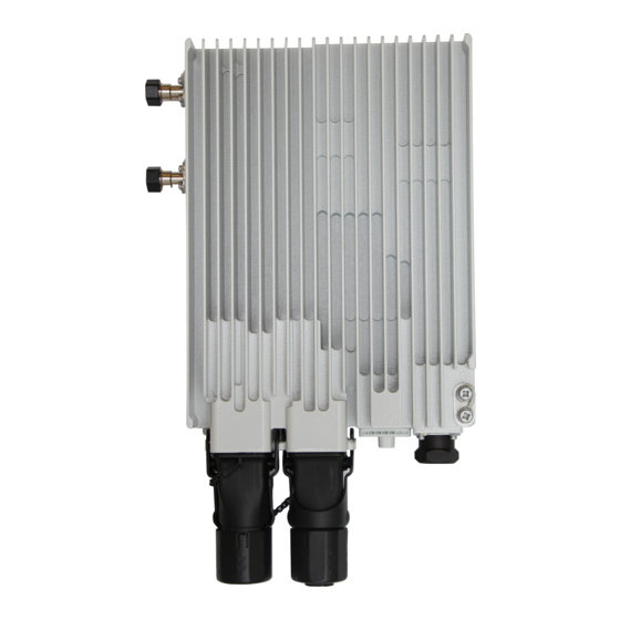
Page 4: Equipment Introduction
Equipment Introduction Equipment Components Appearance and ports Two types of OAU 2F are available for the RTN 320F: OAU 2F (DC option) and OAU 2F (P&E option). Except for the installation of the power cable, other installation operations are the same between the OAU 2F (P&E option) and the OAU 2F (DC option). - Page 5 Equipment Introduction Equipment Components Appearance and ports of the hybrid coupler Mounting kit Joining kit Top view Pole mounting Standby tributary port Mounting hole Mounting hole Port Name Identifier ODU hook hole ODU hook hole Main tributary port MAIN Hose clamp Standby tributary port STANDBY Main tributary port...
- Page 6 Blue: -48 V power cable (connected to the Cable sheath U208 with a 4 GB capacity. negative terminal of the power supply device) If a different model or capacity is required, contact Huawei local offices. DLC/UPC connector The appearance of Netac U208 flash drives varies Power supply device depending on the vendor.
- Page 7 Terminating an Outdoor Network Cable with Shielded RJ45 Connectors Prepare the following tools. Insert the arranged core wires into an RJ45 connector according to the pin assignments and crimp the connector with the crimping tool. Crimp the RJ45 connector. RJ45 connector crimping tool Diagonal pliers Prepare an outdoor network cable and shielded RJ45 connectors.
- Page 8 Installing the OAU 2F Installation at a 1+0 Site Installation procedure Integrated installation Commissioning procedure Split installation Install the OAU 2F on a pole or wall. Install a ground cables of the OAU 2F and For the method of installing an antenna, follow the Power on the OAU 2F.
- Page 9 Installing the OAU 2F Installation at a 2+0 or 1+1 Site Installation procedure Integrated installation Split installation Commissioning procedure For the method of installing an antenna, Install the OAU 2F on a pole or wall. Install a ground cables of the OAU 2F and Power on the OAU 2F.
- Page 10 Installing the OAU 2F Installation at an XPIC Site Installation procedure Integrated installation Split installation Commissioning procedure For the method of installing an antenna, Install the OAU 2F on a pole or wall. Install a ground cables of the OAU 2F and Power on the OAU 2F.
- Page 11 Installing the OAU 2F Installation at a 4+0 or 3+0 Site Installation procedure Integrated installation Split installation Commissioning procedure For the method of installing an antenna, Install the OAU 2F on a pole or wall. Install a ground cables of the OAU 2F and follow the antenna installation guide Power on the OAU 2F.
-
Page 12: Installation Reference
Installation Reference Optional: Installing an OAU 2F on a Pole Fasten the OAU 2F box, which has a conversion bracket, on the Pass the hose clamps through the pole mounting bracket and fix the hose clamps on a pole using Fasten the extra portion of the hose clamps onto pole mounting bracket using screws. - Page 13 Installation Reference Optional: Installing an OAU 2F on an XMC-5D ODU Optional: Installing an OAU 2F on an XMC-3/3H ODU a. Attach the XMC-3/3H ODU hook to the hook hole of the joining kit. b. Install the joining kit to the XMC-3/3H ODU. When installing the OAU 2F to the XMC-5D ODU, two types of splices are available.
- Page 14 Installation Reference Optional: Installing an OAU 2F on an XMC-2H ODU (11GHz) Installing the joining kit on an XMC ODU. Install the joining kit with the OAU 2F XMC ODU to an OAU 2F. XMC-2H ODU (11GHz) Joining kit Installing a Ground Cable for the OAU 2F Installing an IF Cable Conversion Conversion...
- Page 15 Installation Reference Installing the outdoor optical cable, and outdoor Ethernet cables Installing the outdoor optical cable, and outdoor Ethernet cables a: Rotate the expansion cap counterclockwise and Push out the rubber plugs from the bottom of the After the installation, ensure that the length of exposed rubber plug is about 10 mm. loosen it.
- Page 16 Installation Reference Installing a Signal Lightning Surge Protector When a device uses SFP GE electrical modules, it must be used with a signal lightning surge protector. Connect the outdoor network cables to the signal lightning surge protector. Connect the surge end of the protector to GE electrical signals and use SFP GE electrical modules to connect the protect Signal lightning surge protector end to the device.
- Page 17 Installation Reference Selecting ground points Select ground points for the outdoor network cable. Select ground points for the DC cable. Ground the outdoor network cable at the following positions: Ground the DC cable at the following positions: 1. About 0.5 m to 1 m away from the port 1.
- Page 18 Installation Reference Selecting ground points Installing a ground clip Select ground points for the IF cable. Use a box cutter to strip off a section of the cable sheath. Take care not to damage the shield layer. Ground the IF cable at the following positions: 1.
- Page 19 Installation Reference Installing the Outdoor Optical Splitter Loosen the reinforce screws. Open the case cover. Optional: wall-mounting 4 mm hex key Cable distribution area Use a scribe template to determine the positions of mounting holes. Scribe pen Level Fiber routing clips Fiber fixing holes...
- Page 20 Installation Reference Installing the Outdoor Optical Splitter Optional: pole-mounting Install the pole assembly on the pole. Fix the case on the pole assembly and tighten the lower hold hoop. Loosen the screw on the Install the pole assembly on the pole. Complete installation of the pole assembly.
- Page 21 Installation Reference Installing the Outdoor Optical Splitter Guide the lead nylon of outdoor fibers through fiber Remove dustproof caps and insert fiber connectors into appropriate adapters fixing holes, fix the lead nylon and cut off redundant according to labels. part. Port in Fiber Interconne Description...
-
Page 22: Laying Out Cables
Installation Reference Laying out Cables General requirements Requirements for laying out cables outdoors Route cables along the planned path, use outdoor cable ties or feeder clamps to bind cables properly and neatly 1. Bend radius For power and PGND cables, ensure a bend radius of at least three times the cable diameter. at intervals of about 1 meter, and cut off the excess of each cable tie without leaving sharp edges (ensuring a 2. -
Page 23: Checking The Installation
Checking the Installation Checking the Cables of RTN 320F Checking the PI Check Item Check Item All outdoor connections and ground clips are moistureproofed or waterproofed. The PI installation position meets the requirements specified in engineering design documents. The PI is installed securely. The cable connectors are assembled correctly and securely. - Page 24 Appendix Powering on the OAU 2F (DC) Using the Web LCT to Load NE Data Before powering on the equipment, ensure that: The OAU 2F supports use of a network cable to directly connect the NMS port to the Web LCT. It also supports use of a WLAN module to connect to the Web LCT. ...
- Page 25 Appendix Aligning Single-Polarized Antennas Loosen/tighten the elevation adjustment screw to move the local antenna vertically. Adjust the pitch angle until the RSL Use the installation positions and heights of local and remote antennas to determine their azimuths. Adjust the pitch angles of the antennas to the horizontal position. reaches the peak within the tracked range.
- Page 26 Appendix Assembling DC Power Cables Prepare for the assembly. Close the wire clip and tighten the screw to compact Tighten the compact screw in the "+" hole, rotate the connector 180 degrees, and tighten the compact screw the shield layer. Prepare the following tools: dual-head bayonet wrench Components of the connector are shown as follows.
- Page 27 Appendix Treating the IF Ports and Ground Cables of IF Cables and Outdoor Network Cables with Anticorrosive Material and P&E Cable 1. Wrap one layer of PVC tape around the exposed part of a flexible waveguide or a group clip. 2.