Table of Contents
Advertisement
Quick Links
Advertisement
Table of Contents

Related Manuals for Hitachi HIDIC MICRO-EH


Summary of Contents for Hitachi HIDIC MICRO-EH
- Page 1 HITACHI PROGRAMMABLE CONTROLLER APPLICATION MANUAL NJI-350B (X)
- Page 2 Personnel who are to install and operate the equipment should carefully study this manual and any others referred to by it prior to installation and / or operation of the equipment. Hitachi, Ltd. constantly strives to improve its products, and the equipment and the manual(s) that describe it may be different from those already in your possession.
- Page 3 Hitachi neither assumes, nor authorizes any other person to assume for Hitachi, any other liability in connection with the sale of this PLC. This warranty shall not apply to this PLC or any part hereof which has been subject to accident, negligence, alteration, abuse, or misuse.
- Page 4 As the product works with user program and Hitachi, Ltd. cannot test all combination of user program components, it is assumed that a bug or bugs may happen unintentionally. If it is happened: please inform the fact to Hitachi, Ltd. or its representative.
- Page 5 Safety Precautions Read this manual and attached documents thoroughly before installing and operating this unit, and performing maintenance or inspection of this unit in order to use the unit correctly. Be sure to use this unit after acquiring adequate knowledge of the unit, all safety information, and all precautionary information. Also, be sure to deliver this manual to the person in charge of maintenance.
- Page 6 2. Wiring REQUIRED • Always perform grounding (FE terminal). If grounding is not performed, there is a risk of an electric shock or malfunction. CAUTION • Connect a power supply that meets the rating. If a power supply that does not meet the rating is connected, it may result in a fire. •...
- Page 7 4. Maintenance DANGER • Never connect the of the battery in reverse. Also, never charge, disassemble, heat, place in fire, or short circuit the battery. There is a risk of an explosion or fire. PROHIBITED • Never disassemble or modify the unit. These actions may result in a fire, malfunction, or failure.
- Page 8 Revision History Description of Revision Date of Revision Manual Number Appendix-1 Instruction Support 2000/11 NJI-350 (X) FUN92 to 96 of H-4010 -> ×. Appendix-2 Task code H28 Corrected explanation of Timer counter number. Postscript of battery error detection. (3.2 chapters item 2000/12 NJI-350A (X) number 26, 15 chapters (4) )
-
Page 9: Table Of Contents
Table of Contents Chapter 1 Features ............................. 1-1 to 1-2 Chapter 2 System Overview........................2-1 to 2-2 Chapter 3 Function and Performance Specifications ................3-1 to 3-14 General Specifications ......................3-1 Function Specifications......................3-2 Performance Specifications...................... 3-6 3.3.1 Calculation Specifications .................... 3-6 3.3.2 Input Specifications ...................... - Page 10 Chapter 7 Programming..........................7-1 to 7-8 Memory Size and Memory Assignment ................... 7-1 Programming Devices......................7-2 Programming Methods......................7-3 Program Transfer ........................7-7 Chapter 8 High speed counter, PWM/Pulse train output and Analogue I/O..........8-1 to 8-22 Input/Output Function......................8-1 8.1.1 Initial Setting for Input/Output Function ..............
- Page 11 Chapter 10 PLC Installation, Mounting, Wiring..................10-1 to 10-8 10.1 Installation ..........................10-1 10.2 Wiring ............................ 10-3 Chapter 11 Communication Specifications.................... 11-1 to 11-10 11.1 Port function .......................... 11-1 11.2 Port 1............................11-1 11.3 Port 2............................11-3 11.4 General purpose port (Port 1,2) ..................... 11-4 11.5 Modem Control Function.......................
- Page 12 MEMO...
-
Page 13: Chapter 1 Features
Chapter 1 Features Chapter 1 Features 1. Multifunctional all-in-one type PLC The MICRO-EH is a multifunctional all-in-one type PLC that contains all necessary parts—a power supply and CPU parts as well as I/O units--within one unit. Three sizes of PLCs are available: 10, 14, and 28 points. A type with 23 points plus three points of analog I/O having the same size as the 28-point PLC is also available. - Page 14 Chapter 1 Features MEMO...
-
Page 15: Chapter 2 System Overview
Chapter 2 System Overview Chapter 2 System Overview This chapter describes the system configuration of the MICRO-EH. The MICRO-EH is an all-in-one type programmable controller, and has the following system configuration. 1] Basic unit Figure 2.1 10-point type system configuration diagram 1] Basic unit 2] Expansion unit 2] Expansion unit... - Page 16 Chapter 2 System Overview [1] Basic unit [2] Expansion unit [2] Expansion unit [3] Expansion cable [3] Expansion cable [2] Expansion unit [2] Expansion unit [3] Expansion cable [3] Expansion cable Figure 2.3 23,28-point type system configuration diagram No restriction for combination of 14,23,28 points, and basic/expansion unit. 14 points basic unit can handle any type of expansion units, and 23/28 points basic unit as well.
-
Page 17: Chapter 3 Function And Performance Specifications
Chapter 3 Function and Performance Specifications Chapter 3 Function and Performance Specifications General Specifications Item Specification Power supply type Power voltage 100/110/120 V AC (50/60 Hz), 24 V DC 200/220/240 V AC (50/60 Hz) Power voltage fluctuation 85 to 264 V AC wide range 19.2 to 30 V DC range Current consumption... -
Page 18: Function Specifications
Chapter 3 Function and Performance Specifications Function Specifications The functions available in the MICRO-EH are described in the table below. Item Description Basic functions The following functions can be executed when constructing a system using the PLC. 1] An input signal is received from the control object, operations are performed according to the contents of the program created by the user and the results are output as an output signal. - Page 19 Chapter 3 Function and Performance Specifications Item Description Control method With the PLC, the user programs are converted in batch at operation startup, and the programs after conversion will be executed in order as they are read one by one. 1] The method used for data I/O is that after the I/O data (information) is scanned (execution from the head of the program to the end), it is updated in group.
- Page 20 Chapter 3 Function and Performance Specifications Item Description Forced set/reset Forced set and forced reset of the designated I/O can be performed from the programming unit connected to the CPU module. Forced output Output can be forced with respect to the designated I/O number from the programming unit connected to the CPU module.
- Page 21 Chapter 3 Function and Performance Specifications Item Description Interrupt input The external input of the basic unit can be specified for interrupt input. With the interrupt input, the corresponding interrupt program can be executed. PWM output The external output of the basic unit can be specified for pulse width modulated output. In this case, pulses are output at the specified frequency with a duty between 0 and 100 %.
-
Page 22: Performance Specifications
Chapter 3 Function and Performance Specifications Performance Specifications 3.3.1 Calculation Specifications The calculation specifications of the PLC are described below. Model Name 10-point type 14-point type 23/28-point type Type EH-D10DT EH-D14DT EH-A23DRP EH-D28DT EH-D10DTP EH-D14DTP EH-A23DRT EH-D28DTP EH-D10DR EH-A14DR EH-D23DRP EH-A28DRP EH-D14DR EH-A28DRT... -
Page 23: Input Specifications
Chapter 3 Function and Performance Specifications 3.3.2 Input Specifications The input circuit consists of DC input and AC input, with the following specifications. (1) DC input Item Specification Circuit diagram Input voltage 24 V DC Allowable input voltage range 0 to 30 V DC Input impedance Approx. -
Page 24: Output Specifications
Chapter 3 Function and Performance Specifications 3.3.3 Output Specifications (1) DC output (Y100 of EH-*23DRP/A23DRT/*28DRP/*28DRT) Item Specification Circuit diagram Sink type (23/28DRT) Type EH-A23DRT EH-*23DRP EH-*28DRT EH-*28DRP Y100 output specifications Transistor output Transistor output (sink type) (source type) Rated load voltage 24 / 12 / 5 V DC 24 V DC +20 %, -80 % Minimum switching current... - Page 25 Chapter 3 Function and Performance Specifications (2) DC output: LCDC-Low Current (All points of EH-D10DT/DTP, Y102-Y105 of EH-D14DT/DTP, Y102-Y109 of EH-D28DT/DTP, Y*018-Y*021 of EH-D14EDT/D14EDTP) Circuit diagram Item Specification Sink type (EH-D**DT) Output specification Transistor output Rated load voltage 24/12 V DC (+10 %, -15 %) Minimum switching current 1 mA Leak current...
- Page 26 Chapter 3 Function and Performance Specifications (4) DC output (ESCP type): HCDC-High Current (Y100,Y101 of EH-D14DTPS, Y100-Y103 of D28DTPS) Y*016,Y*017 of EH-EDTPS, Y*016-Y*019 of EH-D28EDTPS) Circuit diagram Item Specification Output specification Transistor output Rated load voltage 24/12 V DC (+10 %, -15 %) Minimum switching current 10 mA Leak current...
- Page 27 Chapter 3 Function and Performance Specifications (6) Relay output Item Specification Circuit diagram Rated load voltage 5 to 250 V AC, 5 to 30 V DC Minimum switching current 1 mA Maximum 1 circuit 2 A (24 V DC, 240 V AC) load current 1 common OFF →...
-
Page 28: High-Speed Counter Specifications
Chapter 3 Function and Performance Specifications 3.3.4 High-Speed Counter Specifications Single phase Two phase Available input X0, X2, X4, X6 X0 and X2 in pair Input voltage 15 V 100 µs Count pulse width Maximum count frequency 10 kHz each channel Count register 16 bits Coincidence output... -
Page 29: Analogue Output Specifications
Chapter 3 Function and Performance Specifications Circuit diagram (23 points type) Circuit diagram (Analog expansion unit) IN2JP IN4JP IN2+ IN4+ Current Current IN2- IN4- IN1JP IN1JP IN1+ IN1+ Voltage Voltage IN1- IN1- 3.3.7 Analogue Output Specifications Module type 23 points type module Analog exp. -
Page 30: Potentiometer Analogue Input Specifications
Chapter 3 Function and Performance Specifications 3.3.8 Potentiometer Analogue Input Specifications Number of potentiometer inputs Stored in Ch.1 : WRF03E, Ch.2 WRF03F Input range 0-1023 (H0-H3FF) Resolution 10 bits Input filter By user settings 3.3.9 Interrupt Input Specifications Input that can be used X1, X3, X5, X7 (by user settings) Input voltage 15 V... -
Page 31: Clock Function
Chapter 3 Function and Performance Specifications 3.3.12 Clock Function 23-point and 28-point types have calendar function. This can be operated either by internal output area or task code. 10-point and 14-point types do not have this function. Reading the clock data By turning on the read request (R7F8), the clock data is read out in the reading value area (WRF01B to WRF01F). -
Page 32: Power Supply For Sensor
Chapter 3 Function and Performance Specifications 3.3.13 Power Supply for Sensor The 24 V terminal at the input terminal part can supply current to external equipment (not for all units). If this terminal is used as the power supply for the input part of this unit, the remaining can be used as power supply for the sensors. -
Page 33: Chapter 4 Product Lineup And Wiring
Chapter 4 Product lineup and wiring Chapter 4 Product lineup and wiring Product lineup Basic units Table 4.1 Product lineup list I/O assignment Type Specifications symbol EH-D10DT DC power, DC input × 6, Transistor (sink) output × 4 X48/Y32/empty16 EH-D10DTP DC power, DC input ×... - Page 34 Ladder diagram/Instruction language editor LADDER EDITOR (for Windows® 95/98/NT 4.0) Pro-H HITACHI H-series PLC Programming Software According to IEC 61131-3 (for Windows® 95/98/NT 4.0) Note: HI-LADDER (attached to the GPCL01H) may also be used. However, HL-GPCL and HI-LADDER cannot be used for the 10-point type.
-
Page 35: 10-Point Basic Unit
Chapter 4 Product lineup and wiring 10-Point Basic Unit Name and function of each part Type EH-D10DT, EH-D10DTP, EH- D10DR 6] Input terminals 5] RUN input 9] Mounting hole 1] POW LED 2] OK LED 3] RUN LED 4] Serial port 7] Output terminals 8] Power terminal 10] DIN rail installation clip... -
Page 36: 14-Point Basic Unit
Chapter 4 Product lineup and wiring 14-Point Basic Unit Name and function of each part Type EH-*14*** 10] Terminal cover 5] Input terminals 1] POW LED 2] OK LED 3] RUN LED 8] Expansion 11] Mounting hole connector cover 9] DIP SW cover 6] Output terminals 4] Serial port cover 12] DIN rail installation clip... -
Page 37: 23-Point And 28-Point Basic Unit
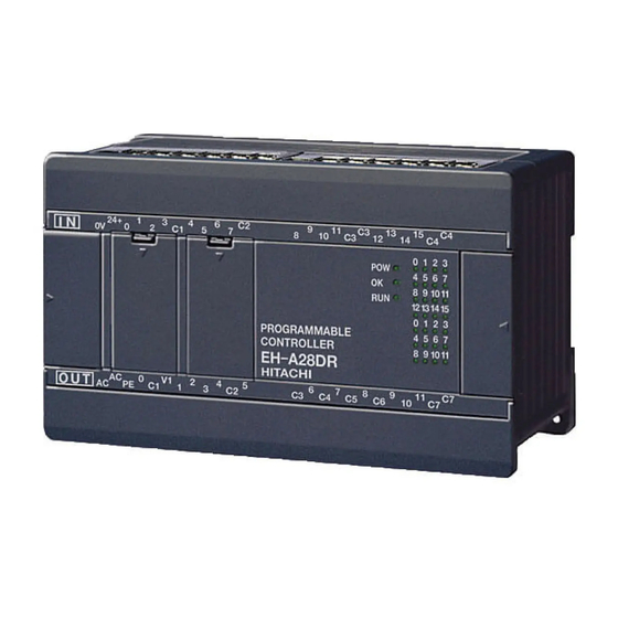
Chapter 4 Product lineup and wiring 23-Point and 28-Point Basic Unit Name and function of each part Type EH-*23*** EH-*28*** 10] Terminal cover 5] Input terminals 13] RS-485 port cover 1] POW LED 2] OK LED 3] RUN LED 11] Mounting 8] Expansion hole connector cover... -
Page 38: Expansion Unit
Chapter 4 Product lineup and wiring Expansion Unit Name and function of each part Type EH-*14ED** (same dimension as 14 pts. basic unit) EH-*28ED** (same dimension as 28 pts. basic unit) EH-*6EAN (same dimension as 14 pts. basic unit) 9] Terminal cover 4] Input terminals 1] POW LED 2] OK LED... -
Page 39: Terminal Layout And Wiring
Chapter 4 Product lineup and wiring Terminal Layout and Wiring 10-point type EH-D10DT, EH-D10DTP Since the DC input is bidirectional, it is possible to reverse the polarity of the power supply. Input power supply 24 V DC In case of EH-D10DTP 24 V In case of EH-D10DT Power supply... - Page 40 Chapter 4 Product lineup and wiring 14-point type EH-A14DR, EH-D14DR * Since the DC input is bidirectional, it is possible to reverse the polarity of the power supply. Input power supply 24V DC Input Output Load power supply AC power supply 24V DC, 100-240V AC 100-240V AC...
- Page 41 Chapter 4 Product lineup and wiring EH-A14AS Power supply for input 100-115V AC Input Output Load power supply 100-240V AC Power supply 100-240V AC EH-D14DTP * Since the DC input is bidirectional, it is possible to reverse the polarity of the power supply. Power supply for input 24V DC Input...
- Page 42 Chapter 4 Product lineup and wiring EH-D14EDTP * Since the DC input is bidirectional, it is possible to reverse the polarity of the power supply. Input Output Power supply Load power supply 24V DC 12/24V DC EH-D14EDT (The input wiring is the same as EH-D14EDTP.) Output Load power supply Power supply...
- Page 43 Chapter 4 Product lineup and wiring 23-point type EH-A23DRP * Since the DC input is bidirectional, it is possible to reverse the polarity of the power supply. Power supply for input, 24V DC IN1+ IN2- IN2JP Input IN1- IN2+ IN1JP Output Load power supply Analog output...
- Page 44 Chapter 4 Product lineup and wiring 28-point type EH-A28DRP * Since the DC input is bidirectional, it is possible to reverse the polarity of the power supply. Power supply for input 24V DC Input Output Power supply Load power supply 100-240V AC TR output power supply 24V DC, 100-240V AC...
- Page 45 Chapter 4 Product lineup and wiring EH-A28AS Power supply for input 100-115V AC Input Output Power supply Load power supply 100-240V AC 100-240V AC EH-D28DTP * Since the DC input is bidirectional, it is possible to reverse the polarity of the power supply. Power supply for input, 24V DC Input...
- Page 46 Chapter 4 Product lineup and wiring EH-A28DR * Since the DC input is bidirectional, it is possible to reverse the polarity of the power supply. Power supply for input 24V DC Input Output Power supply Load power supply 100-240V AC 24V DC, 100-240V AC EH-A28EDR * Since the DC input is bidirectional, it is possible to reverse the polarity of the power supply.
- Page 47 Chapter 4 Product lineup and wiring Analog expansion unit EH-A6EAN (Example of voltage input and voltage output) Voltage input × 4 IN1+ IN2- IN2JP IN3+ IN4- IN4JP IN1- IN1JP IN2+ IN3- IN3JP IN4+ Input and output can be configured as voltage or current independently. Voltage output ×...
-
Page 48: Weights And Power Consumption
Chapter 4 Product lineup and wiring Weights and Power Consumption Type Power consumption (A) Remarks Weight 100V AC 264V AC 24V DC Normal Rush Normal Rush Normal Rush EH-D10DT/DTP/DR 0.12 EH-D14DT/DTP/DTPS 0.16 EH-A14DR 0.06 0.16 EH-D14DR EH-A14AS 0.06 EH-A23DRP/DRT 0.06 EH-D23DRP EH-D28DT/DTP/DTPS EH-A28DRP/DRT... -
Page 49: Exterior Dimensions
Chapter 4 Product lineup and wiring Exterior Dimensions (1) 10-point type (Unit : mm) 70 80 (2) 14-point type, 14-point expansion unit, Analog expansion unit (3) 23-point, 28-point types and 28-point expansion 80 90 4-17... - Page 50 Chapter 4 Product lineup and wiring MEMO 4-18...
-
Page 51: Instruction Specifications
Chapter 5 Instruction Specifications Chapter 5 Instruction Specifications Instruction Classifications The instructions used with the MICRO-EH are classified as shown in the following table. Table 5.1 Instruction classification table Instruction classification Description Type Basic instructions Sequence Timer/counter Relational box Arithmetic instructions Substitution (array variable) Mathematical operations Logical operations... - Page 52 Chapter 5 Instruction Specifications The following lists the instructions. Basic instructions (sequence instructions) Process Instruction time Ladder symbol Process descriptions I/O types used Remarks name (µs) MICRO-EH DER ERR SD Logical Indicates the X, Y operation start commencement of a- R0 to R7BF contact operation.
- Page 53 Chapter 5 Instruction Specifications Process Instruction time Ladder symbol Process descriptions I/O types used Remarks name (µ s) MICRO-EH DER ERR SD MPS Operation Stores the previous None — result push operation result. MRD Operation Reads the stored operation result read result and continues operation.
- Page 54 Chapter 5 Instruction Specifications Basic instructions (relational box) Process Instruction time Ladder symbol Process descriptions I/O types used Remarks name (µ s) MICRO-EH DER ERR SD = Relational When s1 = s2: Continuity [Word] (s1== When s1 ≠ s2: WX, WY, WR, Upper Noncontinuity Timer Counter...
- Page 55 Chapter 5 Instruction Specifications Process Instruction time Ladder symbol Process descriptions I/O types used Remarks name (µ s) MICRO-EH DER ERR SD When s1 < s2: Continuity < Relational [Word] 26.8 (s1< When s1 ≥ s2: WX, WY, WR, < Upper Noncontinuity Timer Counter...
- Page 56 Chapter 5 Instruction Specifications Arithmetic instructions Process Instruction time Ladder symbol Process descriptions I/O types used Remarks name (µ s) MICRO-EH DER ERR SD Substitution d ← s 1 d=s [Bit] 3 I/O: I/O ↕ statement d: Y, R, M 4 I/O: Array s: X, Y, R, M, 4 Array: I/O...
- Page 57 Chapter 5 Instruction Specifications Process Instruction time Ladder symbol Process descriptions I/O types used Remarks name (µ s) MICRO-EH DER ERR SD Logical OR d ← s1+s2 12 d=s1 OR s2 [Bit] Upper d: Y, R, M case: B s1, s2: X, Y, R, Middle case: W [Word]...
- Page 58 Chapter 5 Instruction Specifications Process Instruction time Ladder symbol Process descriptions I/O types used Remarks name (µ s) MICRO-EH DER ERR SD ≤ Relational When s1 < s2, d ← 1 21 d=s1 <= s2 [Word] Upper When s1 ≥ s2, d ← 0 d: Y, R, M case: W expression...
- Page 59 Chapter 5 Instruction Specifications Process Instruction time Ladder symbol Process descriptions I/O types used Remarks name (µ s) MICRO-EH DER ERR SD 10 BSR(d, n) BCD shift [Word] Upper right d: WY, WR, WM, case: W Lower n: WX, WY, WR, case: DW 0→...
- Page 60 Chapter 5 Instruction Specifications Process Instruction time Ladder symbol Process descriptions I/O types used Remarks name (µ s) MICRO-EH DER ERR SD Binary → 18 BCD(d, s) Converts the value of s into [Word] Upper ↕ BCD and stores it in I/O d: WY, WR, WM case: W conversion...
- Page 61 Chapter 5 Instruction Specifications Control instructions Process Instruction time Ladder symbol Process descriptions I/O types used Remarks name (µ s) MICRO-EH DER ERR SD 1 END Normal Indicates the end of a None scan end normal scan. 2 CEND(s) Scan Re-executes normal scan s: X, Y, R, M conditional...
- Page 62 Chapter 5 Instruction Specifications Process Instruction time Ladder symbol Process descriptions I/O types used Remarks name (µ s) MICRO-EH DER ERR SD 4 FUN 82 (s) I/O refresh Refreshes the I/O at the s: WR, WM ↕ (SLREF (s)) (any slot) designated slot.
-
Page 63: Instruction Specification Details
Chapter 5 Instruction Specifications Instruction Specification Details Basic instructions Arithmetic instructions Application instructions Control instructions Transfer instructions FUN instructions 5-13... - Page 64 Chapter 5 Instruction Specifications Item number Basic instructions-1, 2 Name Logical operation start (LD, LDI) Ladder format Condition code Remark Processing time (µs) R7F4 R7F3 R7F2 R7F1 R7F0 Average Maximum ← Instruction format Number of steps Condition Steps — Word Double word TD, SS, Usable I/O...
- Page 65 Chapter 5 Instruction Specifications Item number Basic instructions-3, 4 Name Contact serial connection (AND, ANI) Ladder format Condition code Remark Processing time (µs) R7F4 R7F3 R7F2 R7F1 R7F0 Average Maximum ← Instruction format Number of steps Condition Steps Word Double word TD, SS, Usable I/O...
- Page 66 Chapter 5 Instruction Specifications Item number Basic instructions-5, 6 Name Contact parallel connection (OR, ORI) Ladder format Condition code Remark Processing time (µs) R7F4 R7F3 R7F2 R7F1 R7F0 Average Maximum ← Instruction format Number of steps Condition Steps Word Double word TD, SS, Usable I/O...
- Page 67 Chapter 5 Instruction Specifications Item number Basic instructions-7 Name Negation (NOT) Ladder format Condition code Remark Processing time (µs) R7F4 R7F3 R7F2 R7F1 R7F0 Average Maximum Instruction format Number of steps Condition Steps Word Double word TD, SS, Usable I/O Other CU, CT...
- Page 68 Chapter 5 Instruction Specifications Item number Basic instructions-8 Name Leading edge detection (AND DIF, OR DIF) Ladder format Condition code Remark Processing time (µs) R7F4 R7F3 R7F2 R7F1 R7F0 Average Maximum DIF n DIF n DIF n DIF n ← Instruction format Number of steps AND DIF n...
- Page 69 Chapter 5 Instruction Specifications Item number Basic instructions-9 Name Trailing edge detection (AND DFN, OR DFN) Ladder format Condition code Remark Processing time (µs) R7F4 R7F3 R7F2 R7F1 R7F0 Average Maximum DFN n DFN n DFN n DFN n ← Instruction format Number of steps AND DFN n...
- Page 70 Chapter 5 Instruction Specifications Item number Basic instructions-10 Name Coil output (OUT) Ladder format Condition code Remark Processing time (µs) R7F4 R7F3 R7F2 R7F1 R7F0 Average Maximum ← Instruction format Number of steps Condition Steps OUT n Word Double word TD, SS, Usable I/O Other...
- Page 71 Chapter 5 Instruction Specifications Item number Basic instructions-11, 12 Name Set/reset coil output (SET, RES) Ladder format Condition code Remark Processing time (µs) R7F4 R7F3 R7F2 R7F1 R7F0 Average Maximum Upper case: SET ← Lower case: RES Instruction format Number of steps SET n Condition Steps...
- Page 72 Chapter 5 Instruction Specifications Item number Basic instructions-13, 14 Name Set (start)/reset (cancel) master control (MCS, MCR) Ladder format Condition code Remark Processing time (µs) R7F4 R7F3 R7F2 R7F1 R7F0 Average Maximum MCS n MCS n Upper case: MCS MCR n MCR n ←...
- Page 73 Chapter 5 Instruction Specifications Item number Basic instructions-15, 16, 17 Name Save/read/clear operation result (Branching of ladder) Ladder format Condition code Remark Processing time (µs) R7F4 R7F3 R7F2 R7F1 R7F0 Average Maximum Save Read Clear Instruction format Number of steps Save Condition Steps...
- Page 74 Chapter 5 Instruction Specifications Item number Basic instructions-18 Name Logical block serial connection (ANB) Ladder format Condition code Remark Processing time (µs) R7F4 R7F3 R7F2 R7F1 R7F0 Average Maximum (See Function column) Instruction format Number of steps Condition Steps ...
- Page 75 Chapter 5 Instruction Specifications Item number Basic instructions-19 Name Logical block parallel connection (ORB) Ladder format Condition code Remark Processing time (µs) R7F4 R7F3 R7F2 R7F1 R7F0 Average Maximum (See Function column) Instruction format Number of steps Condition Steps ...
- Page 76 Chapter 5 Instruction Specifications Item number Basic instructions-20 Name Processing box start and end (PROCESSING BOX) Ladder format Condition code Remark Processing time (µs) R7F4 R7F3 R7F2 R7F1 R7F0 Average Maximum Instruction format Number of steps Condition Steps — Word Double word TD, SS,...
- Page 77 Chapter 5 Instruction Specifications Item number Basic instructions-21 Name Relational box start and end (RELATIONAL BOX) Ladder format Condition code Remark Processing time (µs) R7F4 R7F3 R7F2 R7F1 R7F0 Average Maximum Instruction format Number of steps Condition Steps — Word Double word TD, SS,...
- Page 78 Chapter 5 Instruction Specifications Item number Basic instructions-22 Name On delay timer (ON DELAY TIMER) Ladder format Condition code Remark Processing time (µs) R7F4 R7F3 R7F2 R7F1 R7F0 Average Maximum TD n t x s Instruction format Number of steps Condition Steps ...
- Page 79 Chapter 5 Instruction Specifications Program description [Time chart] When input X00000 turns on, TD progress value is updated. When input X00000 turns off, the TD progress value is cleared. X00000 TD10 turns on when progress value ≥ set value. While X00000 is on, the progress value increases, but will not TD10 increase exceeding 65535.
- Page 80 Chapter 5 Instruction Specifications Item number Basic instructions-23 Name Single shot (SINGLE SHOT) Ladder format Condition code Remark Processing time (µs) R7F4 R7F3 R7F2 R7F1 R7F0 Average Maximum SS n t x s Instruction format Number of steps Condition Steps ...
- Page 81 Chapter 5 Instruction Specifications Program description [Time chart] The progress value is updated and SS11 turns on at the leading edge of X00001. SS11 turns off when set value ≥ progress value. X00001 X00001 is turned on at this time, but the single shot startup conditions are ignored because it uses edge trigger.
- Page 82 Chapter 5 Instruction Specifications Item number Basic instructions-24 Name Counter (COUNTER) Ladder format Condition code Remark Processing time (µs) R7F4 R7F3 R7F2 R7F1 R7F0 Average Maximum CU n Instruction format Number of steps Condition Steps OUT CU n s —...
- Page 83 Chapter 5 Instruction Specifications Program description [Time chart] 1] The progress value (count) is cleared to 0 by the counter clear (CL15). While the counter clear is on, the progress value will not be updated. Ignored Ignored 2] The progress value is updated at the leading edge of X00005.
- Page 84 Chapter 5 Instruction Specifications Up (CTU n) and down (CTD n) of up/down counter Item number Name Basic instructions-25, 26 (UP/DOWN COUNTER) Ladder format Condition code Remark Processing time (µs) R7F4 R7F3 R7F2 R7F1 R7F0 Average Maximum CTU n s CTD n Upper case: CTU ...
- Page 85 Chapter 5 Instruction Specifications Program example X00007 CTU17 X00007 CTU17 4 X00008 CTD17 X00008 CTD17 X00009 CL17 X00009 CL17 CT17 R107 CT17 R107 • An example of a word I/O being used as the set value for the circuit shown above. R7E3 R7E3 WR0017=4...
- Page 86 Chapter 5 Instruction Specifications Item number Basic instructions-27 Name Counter clear (COUNTER CLEAR) Ladder format Condition code Remark Processing time (µs) R7F4 R7F3 R7F2 R7F1 R7F0 Average Maximum CL n Instruction format Number of steps Condition Steps OUT CL n s —...
- Page 87 Chapter 5 Instruction Specifications Item number Basic instructions-28 Name =Relational box (=RELATIONAL BOX) Ladder format Condition code Remark Processing time (µs) R7F4 R7F3 R7F2 R7F1 R7F0 Average Maximum (See Function column) Upper case: W Lower case: DW Instruction format Number of steps (s1 == s2) Condition Steps...
- Page 88 Chapter 5 Instruction Specifications Item number Basic instructions-29 Name Signed = Relational box (SIGNED = RELATIONAL BOX) Ladder format Condition code µ Remark Processing time ( R7F4 R7F3 R7F2 R7F1 R7F0 Average Maximum (See Function column) Command format Number of steps (s1 S== s2) Condition Steps...
- Page 89 Chapter 5 Instruction Specifications Item number Basic instructions-30 Name <> Relational box (<> RELATIONAL BOX) Ladder format Condition code Remark Processing time (µs) R7F4 R7F3 R7F2 R7F1 R7F0 Average Maximum (See Function column) Upper case: W 26.8 Lower case: DW Instruction format Number of steps (s1 <>...
- Page 90 Chapter 5 Instruction Specifications Signed <> Relational box (SIGNED <> RELATIONAL Item number Name Basic instructions-31 BOX) Ladder format Condition code µ Remark Processing time ( R7F4 R7F3 R7F2 R7F1 R7F0 Average Maximum (See Function column) 34.5 Command format Number of steps (s1 S<>...
- Page 91 Chapter 5 Instruction Specifications Item number Basic instructions-32 Name <Relational box (<RELATIONAL BOX) Ladder format Condition code Remark Processing time (µs) R7F4 R7F3 R7F2 R7F1 R7F0 Average Maximum (See Function column) Upper case: W 26.8 Lower case: DW Instruction format Number of steps (s1 <...
- Page 92 Chapter 5 Instruction Specifications Item number Basic instructions-33 Name Signed<Relational box (SIGNED < RELATIONAL BOX) Ladder format Condition code µ Remark Processing time ( R7F4 R7F3 R7F2 R7F1 R7F0 Average Maximum (See Function column) 37.5 Command format Number of steps (s1 S<...
- Page 93 Chapter 5 Instruction Specifications ≤ Relational box (≤ RELATIONAL BOX) Item number Basic instructions-34 Name Ladder format Condition code Remark Processing time (µs) R7F4 R7F3 R7F2 R7F1 R7F0 Average Maximum (See Function column) Upper case: W 26.8 Lower case: DW Instruction format Number of steps (s1 <= s2)
- Page 94 Chapter 5 Instruction Specifications Signed ≤ Relational box (SIGNED ≤ RELATINAL BOX) Item number Basic instructions-35 Name Ladder format Condition code µ Remark Processing time ( R7F4 R7F3 R7F2 R7F1 R7F0 Average Maximum (See Function column) 37.5 Command format Number of steps (s1 S<= s2) Condition Steps...
- Page 95 Chapter 5 Instruction Specifications Item number Arithmetic instructions-1 Name Substitution statement (ASSIGNMENT STATEMENT) Ladder format Condition code Remark Processing time (µs) R7F4 R7F3 R7F2 R7F1 R7F0 Average Maximum d = s ↕ Instruction format Number of steps (See following table) Condition Steps d = s...
- Page 96 Chapter 5 Instruction Specifications Program example X00000 DIF0 WR0000 =WX0000 X00001 DIF1 WR0000(WM000)=WX0000 Array variables are used at the substitution destination X00002 DIF2 Array variables are used at the WR0000 =WR0000(WM001) substitution source X00003 DIF3 Array variables are used at both WR0000(WM000)=WR0000(WM001) substitution destination and source Program description...
- Page 97 Chapter 5 Instruction Specifications Item number Arithmetic instructions-2 Name Binary addition (BINARY ADDITION) Ladder format Condition code Remark Processing time (µs) R7F4 R7F3 R7F2 R7F1 R7F0 Average Maximum d = s1 + s2 Upper case: W Lower case: DW ↕...
- Page 98 Chapter 5 Instruction Specifications Item number Arithmetic instructions-3 Name BCD addition (BCD ADDITION) Ladder format Condition code Remark Processing time (µs) R7F4 R7F3 R7F2 R7F1 R7F0 Average Maximum d = s1 B+ s2 Upper case: W Lower case: DW ↕...
- Page 99 Chapter 5 Instruction Specifications Item number Arithmetic instructions-4 Name Binary subtraction (BINARY SUBTRACTION) Ladder format Condition code Remark Processing time (µs) R7F4 R7F3 R7F2 R7F1 R7F0 Average Maximum d = s1 – s2 Upper case: W Lower case: DW ↕...
- Page 100 Chapter 5 Instruction Specifications Item number Arithmetic instructions-5 Name BCD subtraction (BCD SUBTRACTION) Ladder format Condition code Remark Processing time (µs) R7F4 R7F3 R7F2 R7F1 R7F0 Average Maximum d = s1 B– s2 Upper case: W Lower case: DW ↕...
- Page 101 Chapter 5 Instruction Specifications Item number Arithmetic instructions-6 Name Binary multiplication (BINARY MULTIPLICATION) Ladder format Condition code Remark Processing time (µs) R7F4 R7F3 R7F2 R7F1 R7F0 Average Maximum d = s1 × s2 Upper case: W ↕ Lower case: DW Instruction format Number of steps Condition...
- Page 102 Chapter 5 Instruction Specifications Item number Arithmetic instructions-7 Name BCD multiplication (BCD MULTIPLICATION) Ladder format Condition code Remark Processing time (µs) R7F4 R7F3 R7F2 R7F1 R7F0 Average Maximum d = s1 B× s2 Upper case: W Lower case: DW ↕...
- Page 103 Chapter 5 Instruction Specifications Signed binary multiplication (SIGNED BINARY Item number Name Arithmetic instructions-8 MULTIPLICATION) Ladder format Condition code µ Remark Processing time ( R7F4 R7F3 R7F2 R7F1 R7F0 Average Maximum d = s1 S× s2 ↕ Command format Number of steps Condition Steps...
- Page 104 Chapter 5 Instruction Specifications Item number Arithmetic instructions-9 Name Binary division (BINARY DIVISION) Ladder format Condition code Remark Processing time (µs) R7F4 R7F3 R7F2 R7F1 R7F0 Average Maximum d = s1 / s2 Upper case: W Lower case: DW ↕...
- Page 105 Chapter 5 Instruction Specifications Item number Arithmetic instructions-10 Name BCD division Ladder format Condition code Remark Processing time (µs) R7F4 R7F3 R7F2 R7F1 R7F0 Average Maximum d = s1 B/ s2 Upper case: W Lower case: DW ↕ Instruction format Number of steps Condition Steps...
- Page 106 Chapter 5 Instruction Specifications Item number Arithmetic instructions-11 Name Signed binary division Ladder format Condition code µ Remark Processing time ( R7F4 R7F3 R7F2 R7F1 R7F0 Average Maximum d = s1 S/ s2 ↕ ↕ Command format Number of steps Condition Steps d = s1 S/ s2...
- Page 107 Chapter 5 Instruction Specifications Item number Arithmetic instructions-12 Name Logical OR Ladder format Condition code Remark Processing time (µs) R7F4 R7F3 R7F2 R7F1 R7F0 Average Maximum d = s1 OR s2 Upper case: B Middle case: W Instruction format Number of steps Lower case: DW Condition...
- Page 108 Chapter 5 Instruction Specifications Item number Arithmetic instructions-13 Name Logical AND Ladder format Condition code Remark Processing time (µs) R7F4 R7F3 R7F2 R7F1 R7F0 Average Maximum d = s1 AND s2 Upper case: B Middle case: W Instruction format Number of steps Lower case: DW Condition...
- Page 109 Chapter 5 Instruction Specifications Item number Arithmetic instructions-14 Name Exclusive OR Ladder format Condition code Remark Processing time (µs) R7F4 R7F3 R7F2 R7F1 R7F0 Average Maximum d = s1 XOR s2 Upper case: B Middle case: W Instruction format Number of steps Lower case: DW Condition...
- Page 110 Chapter 5 Instruction Specifications Item number Arithmetic instructions-15 Name = Relational expression Ladder format Condition code Remark Processing time (µs) R7F4 R7F3 R7F2 R7F1 R7F0 Average Maximum d = s1 == s2 Instruction format Number of steps Condition Steps ...
- Page 111 Chapter 5 Instruction Specifications Signed = Relational expression Item number Name Arithmetic instructions-16 Ladder format Condition code µ Remark Processing time ( R7F4 R7F3 R7F2 R7F1 R7F0 Average Maximum d = s1 S== s2 Command format Number of steps Condition Steps d = s1 S== s2...
- Page 112 Chapter 5 Instruction Specifications <> Relational expression Item number Name Arithmetic instructions-17 Ladder format Condition code Remark Processing time (µs) R7F4 R7F3 R7F2 R7F1 R7F0 Average Maximum d = s1 <> s2 Instruction format Number of steps Condition Steps ...
- Page 113 Chapter 5 Instruction Specifications Signed <> Relational expression Item number Name Arithmetic instructions-18 Ladder format Condition code µ Remark Processing time ( R7F4 R7F3 R7F2 R7F1 R7F0 Average Maximum d = s1 S<> s2 Command format Number of steps Condition Steps d = s1 S<>...
- Page 114 Chapter 5 Instruction Specifications Item number Arithmetic instructions-19 Name < Relational expression Ladder format Condition code Remark Processing time (µs) R7F4 R7F3 R7F2 R7F1 R7F0 Average Maximum d = s1 < s2 Upper case: W Lower case: DW Instruction format Number of steps Condition Steps...
- Page 115 Chapter 5 Instruction Specifications Signed < Relational expression Item number Name Arithmetic instructions-20 Ladder format Condition code µ Remark Processing time ( R7F4 R7F3 R7F2 R7F1 R7F0 Average Maximum d = s1 S< s2 Command format Number of steps Condition Steps d = s1 S<...
- Page 116 Chapter 5 Instruction Specifications ≤ Relational expression Item number Arithmetic instructions-21 Name Ladder format Condition code Remark Processing time (µs) R7F4 R7F3 R7F2 R7F1 R7F0 Average Maximum d = s1 <= s2 Upper case: W Lower case: DW Instruction format Number of steps Condition Steps...
- Page 117 Chapter 5 Instruction Specifications Signed ≤ Relational expression Item number Name Arithmetic instructions-22 Ladder format Condition code µ Remark Processing time ( R7F4 R7F3 R7F2 R7F1 R7F0 Average Maximum d = s1 S<= s2 Command format Number of steps Condition Steps d = s1 S<= s2...
- Page 118 Chapter 5 Instruction Specifications Item number Application instructions-1 Name Bit set Ladder format Condition code Remark Processing time (µs) R7F4 R7F3 R7F2 R7F1 R7F0 Average Maximum BSET (d, n) Upper case: W Lower case: DW Instruction format Number of steps Condition Steps ...
- Page 119 Chapter 5 Instruction Specifications Item number Application instructions-2 Name Bit reset Ladder format Condition code Remark Processing time (µs) R7F4 R7F3 R7F2 R7F1 R7F0 Average Maximum BRES (d, n) Upper case: W Lower case: DW Instruction format Number of steps Condition Steps ...
- Page 120 Chapter 5 Instruction Specifications Item number Application instructions-3 Name Bit test Ladder format Condition code Remark Processing time (µs) R7F4 R7F3 R7F2 R7F1 R7F0 Average Maximum BTS (d, n) Upper case: W Lower case: DW ↕ Instruction format Number of steps Condition Steps ...
- Page 121 Chapter 5 Instruction Specifications Program description When WR0001 = H1234 at the leading edge of X00000 (WR0001 = 0001001000110100) 20 (decimal) If DR0100 = H00000000, DR0102 = HFFFFFFFF and DR0104 = H5555AAAA are set, the 20th bit of DR0100 is set to “1” by the BSET at the leading edge of X00000.
- Page 122 Chapter 5 Instruction Specifications Item number Application instructions-4 Name Shift right Ladder format Condition code Remark Processing time (µs) R7F4 R7F3 R7F2 R7F1 R7F0 Average Maximum SHR (d, n) Upper case: W Lower case: DW ↕ Instruction format Number of steps Condition Steps ...
- Page 123 Chapter 5 Instruction Specifications Program example X00000 X00000 R7F2 OUT R7F2 X00000 ..Defective unit input X00001 To SD AND DIF1 X00001 DIF1 SHR (DR0000,1) X00001 ..Conveyor movement (DR0000,1) R7F0 Y00100 Y00001 .
- Page 124 Chapter 5 Instruction Specifications Item number Application instructions-5 Name Shift left Ladder format Condition code Remark Processing time (µs) R7F4 R7F3 R7F2 R7F1 R7F0 Average Maximum SHL (d, n) Upper case: W Lower case: DW ↕ Instruction format Number of steps Condition Steps ...
- Page 125 Chapter 5 Instruction Specifications Item number Application instructions-6 Name Rotate right Ladder format Condition code Remark Processing time (µs) R7F4 R7F3 R7F2 R7F1 R7F0 Average Maximum ROR (d, n) Upper case: W Lower case: DW ↕ Instruction format Number of steps Condition Steps ...
- Page 126 Chapter 5 Instruction Specifications Item number Application instructions-7 Name Rotate left Ladder format Condition code Remark Processing time (µs) R7F4 R7F3 R7F2 R7F1 R7F0 Average Maximum ROL (d, n) Upper case: W Lower case: DW ↕ Instruction format Number of steps Condition Steps ...
- Page 127 Chapter 5 Instruction Specifications Program example X00001 DIF1 X00001 R7F0= 0 AND DIF1 ROL(DR0000,1) ROL(DR0002,1) R7F0 = 0 (DR0000,1) (DR0002,1) Program description • When X00001 rises, the 64-bit data is shifted one bit at a time. The space after the shift is filled with “0.” Overall movement (R7F0) DR0002...
- Page 128 Chapter 5 Instruction Specifications Item number Application instructions-8 Name Logical shift right Ladder format Condition code Remark Processing time (µs) R7F4 R7F3 R7F2 R7F1 R7F0 Average Maximum LSR (d, n) Upper case: W Lower case: DW ↕ Instruction format Number of steps Condition Steps...
- Page 129 Chapter 5 Instruction Specifications Item number Application instructions-9 Name Logical shift left Ladder format Condition code Remark Processing time (µs) R7F4 R7F3 R7F2 R7F1 R7F0 Average Maximum LSL (d, n) Upper case: W Lower case: DW ↕ Instruction format Number of steps Condition Steps...
- Page 130 Chapter 5 Instruction Specifications Item number Application instructions-10 Name BCD shift right Ladder format Condition code Remark Processing time (µs) R7F4 R7F3 R7F2 R7F1 R7F0 Average Maximum BSR (d, n) Upper case: W Lower case: DW Instruction format Number of steps Condition Steps ...
- Page 131 Chapter 5 Instruction Specifications Item number Application instructions-11 Name BCD shift left Ladder format Condition code Remark Processing time (µs) R7F4 R7F3 R7F2 R7F1 R7F0 Average Maximum BSL (d, n) Upper case: W Lower case: DW Instruction format Number of steps Condition Steps ...
- Page 132 Chapter 5 Instruction Specifications Item number Application instructions-12 Name Block transfer (MOVE) Ladder format Condition code Remark Processing time (µs) R7F4 R7F3 R7F2 R7F1 R7F0 Average Maximum MOV (d, s, n) ↕ Instruction format Number of steps As per the table below.
- Page 133 Chapter 5 Instruction Specifications Program example • The data in WM000 to WM01F is transferred to the area WR020 to WR03F. R001 DIF0 MOV (WR020,WM000,32) R7F4 Y00100 R001 AND DIF0 MOV (WR020,WM000,32) R7F4 Y00100 Program description • 32 words of data are transferred. Transfer source area Transfer destination area WM000...
- Page 134 Chapter 5 Instruction Specifications Item number Application instructions-13 Name Copy Ladder format Condition code Remark Processing time (µs) R7F4 R7F3 R7F2 R7F1 R7F0 Average Maximum COPY (d, s, n) ↕ Instruction format Number of steps As per the table below. Condition Steps COPY (d, s, n)
- Page 135 Chapter 5 Instruction Specifications Program example The default value (H2020) is set in the range of WR0100 to WR01FE. R7E3 LD R7E3 COPY (WR0100, H2020,255) COPY (WR0100, H2020, 255) Program description WR0100 to WR01FE is considered as the communication data area and is filled with space code (H20) as the default value during the first scan after RUN starts.
- Page 136 Chapter 5 Instruction Specifications Item number Application instructions-14 Name Block exchange (EXCHANGE) Ladder format Condition code Remark Processing time (µs) R7F4 R7F3 R7F2 R7F1 R7F0 Average Maximum XCG (d1, d2, n) ↕ Instruction format Number of steps As per the table below.
- Page 137 Chapter 5 Instruction Specifications Item number Application instructions-15 Name Ladder format Condition code Remark Processing time (µs) R7F4 R7F3 R7F2 R7F1 R7F0 Average Maximum NOT (d) Upper case: B Instruction format Number of steps Middle case: W Condition Steps NOT (d) Lower case: DW...
- Page 138 Chapter 5 Instruction Specifications Item number Application instructions-16 Name Two's complement (NEGATE) Ladder format Condition code Remark Processing time (µs) R7F4 R7F3 R7F2 R7F1 R7F0 Average Maximum NEG (d) Upper case: W Lower case: DW Instruction format Number of steps Condition Steps ...
- Page 139 Chapter 5 Instruction Specifications Item number Application instructions-17 Name Absolute value Ladder format Condition code Remark Processing time (µs) R7F4 R7F3 R7F2 R7F1 R7F0 Average Maximum ABS (d, s) Upper case: W Lower case: DW ↕ Instruction format Number of steps Condition Steps ...
- Page 140 Chapter 5 Instruction Specifications Binary → BCD conversion Item number Application instructions-18 Name Ladder format Condition code Remark Processing time (µs) R7F4 R7F3 R7F2 R7F1 R7F0 Average Maximum BCD (d, s) Upper case: W Lower case: DW ↕ Instruction format Number of steps Condition Steps...
- Page 141 Chapter 5 Instruction Specifications BCD → Binary conversion Item number Application instructions-19 Name Ladder format Condition code Remark Processing time (µs) R7F4 R7F3 R7F2 R7F1 R7F0 Average Maximum BIN (d, s) Upper case: W Lower case: DW ↕ Instruction format Number of steps Condition Steps...
- Page 142 Chapter 5 Instruction Specifications Item number Application instructions-20 Name Decode Ladder format Condition code Remark Processing time (µs) R7F4 R7F3 R7F2 R7F1 R7F0 Average Maximum DECO (d, s, n) ↕ Instruction format Number of steps As per the table below. Condition Steps DECO (d, s, n)
- Page 143 Chapter 5 Instruction Specifications Item number Application instructions-21 Name Encode Ladder format Condition code Remark Processing time (µs) R7F4 R7F3 R7F2 R7F1 R7F0 Average Maximum ENCO (d, s, n) ↕ ↕ Instruction format Number of steps As per the table below.
- Page 144 Chapter 5 Instruction Specifications Item number Application instructions-22 Name Bit count Ladder format Condition code Remark Processing time (µs) R7F4 R7F3 R7F2 R7F1 R7F0 Average Maximum BCU (d, s) Upper case: W Lower case: DW Instruction format Number of steps Condition Steps ...
- Page 145 Chapter 5 Instruction Specifications Item number Application instructions-23 Name Swap Ladder format Condition code Remark Processing time (µs) R7F4 R7F3 R7F2 R7F1 R7F0 Average Maximum SWAP (d) Instruction format Number of steps Condition Steps SWAP (d) Word Double word TD, SS, Usable I/O Other...
- Page 146 Chapter 5 Instruction Specifications Item number Application instructions-24 Name Unit Ladder format Condition code Remark Processing time (µs) R7F4 R7F3 R7F2 R7F1 R7F0 Average Maximum UNIT (d, s, n) ↕ Instruction format Number of steps As per the table below. Condition Steps UNIT (d, s, n)
- Page 147 Chapter 5 Instruction Specifications Program example X00001 DIF0 UNIT (WY0010, WR0000, 3) X00001 AND DIF0 UNIT (WY0010, WR0000, 3) Program description A 3-digit BCD input display device is connected to the WY0010, and each digit displays WR0000 to WR0002 data independently.
- Page 148 Chapter 5 Instruction Specifications Item number Application instructions-25 Name Distribute Ladder format Condition code Remark Processing time (µs) R7F4 R7F3 R7F2 R7F1 R7F0 Average Maximum DIST (d, s, n) ↕ Instruction format Number of steps As per the table below. Condition Steps DIST (d, s, n)
- Page 149 Chapter 5 Instruction Specifications Program example X01001 DIF0 DIST (WR0000, WX0000, 4) X00001 AND DIF0 DIST (WR0000, WX0000, 4) Program description A 4-bit 4-digit Digit switch is connected to the WX0000, and the data for each digit is stored in WR0000 to WR0003 as independent data.
- Page 150 Chapter 5 Instruction Specifications Item number Control instructions-1 Name Normal scan end Ladder format Condition code Remark Processing time (µs) R7F4 R7F3 R7F2 R7F1 R7F0 Average Maximum Instruction format Number of steps Condition Steps Word Double word TD, SS, Usable I/O Other CU, CT...
- Page 151 Chapter 5 Instruction Specifications Item number Control instructions-2 Name Scan conditional end Ladder format Condition code Remark Processing time (µs) R7F4 R7F3 R7F2 R7F1 R7F0 Average Maximum CEND (s) Upper case : Conditions Instruction format Number of steps do not meet Condition Steps Lower case :...
- Page 152 Chapter 5 Instruction Specifications Item number Control instructions-3 Name Unconditional jump (JUMP) Ladder format Condition code Remark Processing time (µs) R7F4 R7F3 R7F2 R7F1 R7F0 Average Maximum JMP n Instruction format Number of steps Condition Steps JMP n Word Double word TD, SS, Usable I/O...
- Page 153 Chapter 5 Instruction Specifications Item number Control instructions-4 Name Conditional jump Ladder format Condition code Remark Processing time (µs) R7F4 R7F3 R7F2 R7F1 R7F0 Average Maximum CJMP n (s) Upper case : Conditions Instruction format Number of steps do not meet Condition Steps Lower case :...
- Page 154 Chapter 5 Instruction Specifications Syntax of JMP, CJMP 6] An overlap of JMP instructions with the same code 1] LBL n with the same code number as the code number is valid. number n of the JMP instruction is required. JMP 5 •...
- Page 155 Chapter 5 Instruction Specifications Item number Control instructions-5 Name Label Ladder format Condition code Remark Processing time (µs) R7F4 R7F3 R7F2 R7F1 R7F0 Average Maximum LBL n Instruction format Number of steps Condition Steps LBL n Word Double word TD, SS, Usable I/O Other...
- Page 156 Chapter 5 Instruction Specifications Item number Control instructions-6 Name Ladder format Condition code Remark Processing time (µs) R7F4 R7F3 R7F2 R7F1 R7F0 Average Maximum FOR n (s) Instruction format Number of steps Condition Steps FOR n (s) Word Double word TD, SS, Usable I/O Other...
- Page 157 Chapter 5 Instruction Specifications Item number Control instructions-7 Name NEXT Ladder format Condition code Remark Processing time (µs) R7F4 R7F3 R7F2 R7F1 R7F0 Average Maximum NEXT n Instruction format Number of steps Condition Steps NEXT n Word Double word TD, SS, Usable I/O Other...
- Page 158 Chapter 5 Instruction Specifications Syntax of FOR to NEXT 1] A NEXT instruction with the same code number as the 5] It is possible to escape from a FOR to NEXT loop code number n of the FOR instruction is required after using a jump instruction.
- Page 159 Chapter 5 Instruction Specifications Item number Control instructions-8 Name Call subroutine Ladder format Condition code Remark Processing time (µs) R7F4 R7F3 R7F2 R7F1 R7F0 Average Maximum CAL n Instruction format Number of steps Condition Steps CAL n Word Double word TD, SS, Usable I/O Other...
- Page 160 Chapter 5 Instruction Specifications Item number Control instructions-9 Name Start subroutine program Ladder format Condition code Remark Processing time (µs) R7F4 R7F3 R7F2 R7F1 R7F0 Average Maximum SB n Instruction format Number of steps Condition Steps SB n Word Double word TD, SS, Usable I/O...
- Page 161 Chapter 5 Instruction Specifications Item number Control instructions-10 Name End of subroutine program (RETURN SUBROUTINE) Ladder format Condition code Remark Processing time (µs) R7F4 R7F3 R7F2 R7F1 R7F0 Average Maximum Instruction format Number of steps Condition Steps Word Double word TD, SS, Usable I/O Other...
- Page 162 Chapter 5 Instruction Specifications Item number Control instructions-11 Name Start interrupt scan program (INTERRUPT) Ladder format Condition code Remark Processing time (µs) R7F4 R7F3 R7F2 R7F1 R7F0 Average Maximum INT n Instruction format Number of steps Condition Steps INT n Word Double word TD, SS,...
- Page 163 Chapter 5 Instruction Specifications Item number Control instructions-12 Name End interrupt scan program (RETURN INTERRUPT) Ladder format Condition code Remark Processing time (µs) R7F4 R7F3 R7F2 R7F1 R7F0 Average Maximum Instruction format Number of steps Condition Steps Word Double word TD, SS, Usable I/O Other...
- Page 164 Chapter 5 Instruction Specifications Syntax of SB n, RTS, INT n and RTI 1] A subroutine can be programmed between a normal scan 5] It is also possible to program a subroutine with and interrupt scan, between two interrupt scans, or after multiple entry points and one exit.
- Page 165 Chapter 5 Instruction specifications Item number Name Transfer command-1 General purpose port communication command Ladder format Condition code Remark Processing time (µs) R7F4 R7F3 R7F2 R7F1 R7F0 Average Maximum TRNS 0 (d, s, t) ↕ Command format Number of steps 2,078 Condition Steps...
- Page 166 Chapter 5 Instruction specifications [3] Address of sending area : Address number and address type are configured in 2 words as below. Type : WR → H000A WM → H000C I/O No.: H0000 - [4] Reserved data size for data sending. : This is not actual data size but reserved size. Set it by "Word". [5] Address of receiving area : Address number and address type are configured in 2 words as below.
- Page 167 Chapter 5 Instruction specifications Received data is defined by either of following 4 ways depending on setting in [7] s+A to [9] s+C. Start code and data size Data length s+A : Data length (Byte) s+B : H80 =Start code) Start code s+C : H0000 (b) Start and end code...
- Page 168 Chapter 5 Instruction specifications [9] Timeout : This bit is set "1" when timeout detected. [A] Input buffer full : This bit is set "1" when input buffer full [B] Conflict error : This bit is set "1" when TRNS 0 or RECV 0 commands are duplicated. Bit [6] to [B] is reset at initializing and TRNS 0 executed.
- Page 169 Chapter 5 Instruction specifications Sample program R7E3 R7E3 : 1 scan ON Timeout = 0 WM103 = 0 WM104 = H000A Reserve area for data sending : WM105 = H0000 16 words from WR0 WM106 = 16 WM107 = H000A WR100 Reserve area for data receiving : WM108 = H0100...
- Page 170 Chapter 5 Instruction specifications TRNS/RECV command return code table Name Description Countermeasure Return code Completed properly Operation completed without error Range error Parameter "s" and "t" is out of available I/O range. Reserve area for sending Parameter setting is wrong. setting error Reserve area for sending Parameter is out of available I/O range.
- Page 171 Chapter 5 Instruction specifications Item number Name Transfer command-2 General purpose port communication command Ladder format Condition code Remark Processing time (µs) R7F4 R7F3 R7F2 R7F1 R7F0 Average Maximum RECV 0 (d, s, t) ↕ Command format Number of steps 2,064 Condition Steps...
- Page 172 Chapter 5 Instruction specifications [3] Address of sending area : Address number and address type are configured in 2 words as below. Type : WR → H000A WM → H000C I/O No.: H0000 - [4] Reserved data size for data sending. : This is not actual data size but reserved size. Set it by "Word". [5] Address of receiving area : Address number and address type are configured in 2 words as below.
- Page 173 Chapter 5 Instruction specifications "t" parameter : Set by user [0] Execution bit: Set "1" by user program to send data. This bit is reset after communication completed. [1] Communication completed : This bit is set "1" when communication completed without error, and reset at communication starting. [2] Communication failed : This bit is set "1"...
- Page 174 Chapter 5 Instruction Specifications Item number FUN instructions-1 Name General purpose port switching Ladder format Condition code Remark Processing time (µs) R7F4 R7F3 R7F2 R7F1 R7F0 Average Maximum FUN 5 (s) ↕ Instruction format Number of steps Condition Steps FUN 5 (s) —...
- Page 175 Chapter 5 Instruction Specifications Item number FUN instructions-2 Name I/O refresh (All points) Ladder format Condition code Remark Processing time (µs) R7F4 R7F3 R7F2 R7F1 R7F0 Average Maximum FUN 80 (s) * (ALREF (s)) ↕ Instruction format Number of steps Condition Steps FUN 80 (s)
- Page 176 Chapter 5 Instruction Specifications Item number FUN instructions-3 Name I/O refresh (Input/output) Ladder format Condition code Remark Processing time (µs) R7F4 R7F3 R7F2 R7F1 R7F0 Average Maximum FUN 81 (s) * (IOREF (s)) ↕ Instruction format Number of steps Condition Steps FUN 81 (s)
- Page 177 Chapter 5 Instruction Specifications Item number FUN instructions-4 Name I/O Refresh (slot) Ladder format Condition code Remark Processing time (µs) R7F4 R7F3 R7F2 R7F1 R7F0 Average Maximum FUN 82 (s) * (SLREF (s)) ↕ Instruction format Number of steps Condition Steps FUN 82 (s)
- Page 178 Chapter 5 Instruction Specifications Notes • Set the unit number (0 to 3) and slot number (0 to 1) after s+1. For other set values, DER is set to “1” and that slot will not be processed. • If there is no I/O assignment to the designated slot, DER is set to “1” and that slot will not be processed. •...
- Page 179 Chapter 5 Instruction Specifications Item number FUN instructions-5 Name High-speed Counter Operation Control Ladder format Condition code Remark Processing time (µs) R7F4 R7F3 R7F2 R7F1 R7F0 Average Maximum FUN 140 (s) ↕ Instruction format Number of steps Condition Steps FUN 140 (s) —...
- Page 180 Chapter 5 Instruction Specifications Item number FUN instructions-6 Name High-speed Counter Coincidence Output Control Ladder format Condition code Remark Processing time (µs) R7F4 R7F3 R7F2 R7F1 R7F0 Average Maximum FUN 141 (s) ↕ Instruction format Number of steps Condition Steps FUN 141 (s) —...
- Page 181 Chapter 5 Instruction Specifications High-speed Counter Up-Count/Down-count Control (Single Item number Name FUN instructions-7 phase counter only) Ladder format Condition code Remark Processing time (µs) R7F4 R7F3 R7F2 R7F1 R7F0 Average Maximum FUN 142 (s) ↕ Instruction format Number of steps Condition Steps FUN 142 (s)
- Page 182 Chapter 5 Instruction Specifications Item number FUN instructions-8 Name High-speed Counter Current Value Replacement Ladder format Condition code Remark Processing time (µs) R7F4 R7F3 R7F2 R7F1 R7F0 Average Maximum FUN 143 (s) ↕ Instruction format Number of steps Condition Steps FUN 143 (s) —...
- Page 183 Chapter 5 Instruction Specifications Item number FUN instructions-9 Name High-speed counter current value reading Ladder format Condition code Remark Processing time (µs) R7F4 R7F3 R7F2 R7F1 R7F0 Average Maximum FUN 144 (s) ↕ Instruction format Number of steps Condition Steps FUN 144 (s) —...
- Page 184 Chapter 5 Instruction Specifications Item number FUN instructions-10 Name High-speed counter current value clear Ladder format Condition code Remark Processing time (µs) R7F4 R7F3 R7F2 R7F1 R7F0 Average Maximum FUN 145 (s) ↕ Instruction format Number of steps Condition Steps FUN 145 (s) —...
- Page 185 Chapter 5 Instruction Specifications Item number FUN instructions-11 Name High-speed counter preset Ladder format Condition code Remark Processing time (µs) R7F4 R7F3 R7F2 R7F1 R7F0 Average Maximum FUN 146 (s) ↕ Instruction format Number of steps Condition Steps FUN 146 (s) —...
- Page 186 Chapter 5 Instruction Specifications Program example DIF6 AND DIF6 WR60 = H0100 WR61 = 5000 WR60 = H100 WR62 = 10000 WR61 = 5000 FUN 146 (WR60) WR62 = 10000 FUN 146 ( WR60 ) Program description • Sets both the on-preset value and off-preset value in the counter No. 1. Sets 5000 for the on-preset value and 10000 for the off-preset value.
- Page 187 Chapter 5 Instruction Specifications Item number FUN instructions-12 Name PWM operation control Ladder format Condition code Remark Processing time (µs) R7F4 R7F3 R7F2 R7F1 R7F0 Average Maximum FUN 147 (s) ↕ Instruction format Number of steps Condition Steps FUN 147 (s) —...
- Page 188 Chapter 5 Instruction Specifications Item number FUN instructions-13 Name PWM Frequency on-duty changes Ladder format Condition code Remark Processing time (µs) R7F4 R7F3 R7F2 R7F1 R7F0 Average Maximum FUN 148 (s) ↕ Instruction format Number of steps Condition Steps FUN 148 (s) —...
- Page 189 Chapter 5 Instruction Specifications Notes • If a value other than H01 to H04 is specified as the PWM output number, and if the on-duty value is outside the effective range, DER will be set to “1” and no processing will be performed. •...
- Page 190 Chapter 5 Instruction Specifications Item number FUN instructions-14 Name Pulse output control Ladder format Condition code Remark Processing time (µs) R7F4 R7F3 R7F2 R7F1 R7F0 Average Maximum FUN 149 (s) ↕ Instruction format Number of steps Condition Steps FUN 149 (s) —...
- Page 191 Chapter 5 Instruction Specifications Item number FUN instructions-15 Name Pulse frequency output setting changes Ladder format Condition code Remark Processing time (µs) R7F4 R7F3 R7F2 R7F1 R7F0 Average Maximum FUN 150 (s) ↕ Instruction format Number of steps Condition Steps FUN 150 (s) —...
- Page 192 Chapter 5 Instruction Specifications Notes • If the pulse output number is set to a value other than H01 to H04, DER will be set to “1”and no processing will be performed. • If the external I/O corresponding to the pulse output number is set to a function other than pulse output, DER will be set to “1”and no processing will be performed.
- Page 193 Chapter 5 Instruction Specifications Item number FUN instructions-16 Name Pulse output with acceleration/deceleration Ladder format Condition code µ Remark Processing time ( R7F4 R7F3 R7F2 R7F1 R7F0 Average Maximum FUN 151 (s) ↕ Instruction format Number of steps Condition Steps FUN 151 (s) Word...
- Page 194 Chapter 5 Instruction Specifications Notes When this instruction is executed, the maximum frequency is stored in the special internal output’s pulse output frequency (WRF072 to WFR075), and the number of output pulses is stored in the special internal output’s number of output pulses (WRF07A to WRF07D) respectively.
- Page 195 Chapter 5 Instruction Specifications Item number FUN instructions-17 Name BOX comment Ladder format Condition code Remark Processing time (µs) R7F4 R7F3 R7F2 R7F1 R7F0 Average Maximum FUN 254 (s) * (BOXC (s) ) Instruction format Number of steps Condition Steps FUN 254 (s)
- Page 196 Chapter 5 Instruction Specifications 5-146...
-
Page 197: Chapter 6 I/O Specifications
Chapter 6 I/O Specifications Chapter 6 I/O Specifications Table 6.1 lists the input/output classifications and input/output point types that can be used with the MICRO-EH Table 6.1 Usable I/O classifications and point types 10-point 14-point 23-point 28-point type type type type Function Name... -
Page 198: I/O Assignment
Chapter 6 I/O Specifications I/O Assignment I/O assignment and I/O address are listed below. Table 6.2 I/O assignment and I/O address 10-point 14-point 23-point 28-point Type I/O assignment type type type type Slot 0 : X48 X0-5 X0-7 X0-12 X0-15 Digital Slot 1 : Y32 Y100-103... -
Page 199: External I/O Numbers
Chapter 6 I/O Specifications External I/O Numbers When starting an operation of the MICRO-EH, a user program is executed (scanned) after the input refresh processing (receiving external input data) is performed. Operations are performed according to the contents of the user program, and the next input refresh processing and output refresh processing (operation results are reflected in the external output) are performed. - Page 200 Chapter 6 I/O Specifications The following explains the external I/O assignment. The external I/O numbers for the MICRO-EH system are expressed with the following conventions. Table 6.6 List of external I/O classification and data type Classification I/O classification Data type Remarks External input Bit type...
-
Page 201: Internal Output Numbers
Chapter 6 I/O Specifications Internal Output Numbers Memory is available as an internal output area in the CPU module. There are three areas: bit dedicated area (R), word dedicated area (WR), and bit/word shared area (M/WM). Table 6.8 List of I/O number conventions for external I/O Data type Numbering convention Example... -
Page 202: Memory Size And Memory Assignment
Chapter 7 Programming Chapter 7 Programming Memory Size and Memory Assignment Table 7.1. Lists the programming specifications for the MICRO-EH. Table 7.1 Programming specifications Item 10/14-point type 23/28-point type Program size 3 k steps (3072 steps) Instruction size 32 bits/1 step Memory specification SRAM Backup with a battery is not possible... -
Page 203: Programming Devices
Chapter 7 Programming Programming Devices The following methods are used to create the user programs. Table 7.2 Programming methods Programming device used Concept of operation Remarks Personal computer software [For off-line/on-line operation] • I/O assignment information (LADDER EDITOR, etc.) Creates an I/O assignment table, inputs the program to be can be read. -
Page 204: Programming Methods
Chapter 7 Programming Programming Methods The following shows the system configuration using a personal computer and the procedures for creating a user program using personal computer software. Please note that cables differ depending on the personal computer and software used. Table 7.3 System configuration using a personal computer Personal computer DOS/V PC... - Page 205 Chapter 7 Programming Table 7.4 List of procedures for creating a program Create new program Modify Test operation, adjustment Item Off-line Off-line On-line On-direct Start Start Start Start Select off-line Select on-line Select off-line Select on-line Regenerate from FD, etc. Regenerate from FD, etc.
- Page 206 Chapter 7 Programming The user program is managed in circuit units. One circuit can describe nine contact points (a-type contact point or b-type contact point) and seven coils as shown in the figure below. Figure 7.1 Size of one circuit Or, one relational box can be described using the width of three contact points.
- Page 207 Chapter 7 Programming In addition, if loop symbols are used, a circuit containing up to 57 contact points and one coil can be entered within seven lines. However, an OR circuit cannot be input after a loop. Figure 7.3 Example when using loop symbols A processing box can be placed at the coil position.
-
Page 208: Program Transfer
Chapter 7 Programming Program Transfer The MICRO-EH stores the user programs written from the peripheral units in the execution memory (RAM). Then, it transfers the user programs to the FLASH memory (backup memory) utilizing the idle time of the MPU in the internal area of the MICRO-EH. - Page 209 Chapter 7 Programming Note 1) The following lists the special internal outputs for various settings that can be transferred to the backup memory by the Memory Request for Various Settings Flag (R7F6). Table 7.5 List of special internal outputs that can be stored Special internal output Function that can be stored...
-
Page 210: Input/Output Function
Chapter 8 High-speed counter, PWM / Pulse train output and Analogue I/O Chapter 8 High-speed counter, PWM / Pulse train output and Analogue I/O The MICRO-EH operates in four operation modes. By selecting the proper operation mode, input/output points can be assigned to the counter input, interrupt input, pulse output, and PWM output functions, instead of the normal input/output function. -
Page 211: Operation Mode
Chapter 8 High-speed counter, PWM / Pulse train output and Analogue I/O 8.1.2 Operation Mode Select one mode from the 5 modes shown in Table 8.1 (mode 10 described in following pages.) and set the mode number in the special internal output WRF070 when the CPU is in STOP status. If parameter in WRF070 is not saved by R7F6, the value will be 0 at the next power on. -
Page 212: Input/Output Setting
Chapter 8 High-speed counter, PWM / Pulse train output and Analogue I/O 8.1.3 Input/Output Setting Configure each I/O setting in the special internal output (WRF071) and make it effective by setting R7F5 ON in CPU STOP status. This information is normally reset at every power on, but this can be saved in the FLASH memory by setting R7F5 ON after that. -
Page 213: Input/Output Setting (Mode 10)
Chapter 8 High-speed counter, PWM / Pulse train output and Analogue I/O 8.1.4 Input/Output Setting (Mode 10) Mode 10 had been added since Ver. 01.13. I/O assignment of mode 10 is very flexible as follows. Parameter setting is compatible with existing mode 0 to 3 except for WRF071. Operation of FUN command (FUN 140 - 150) is same for all the mode 0 to 10. -
Page 214: Special Output Operation In Cpu Stop Status
Chapter 8 High-speed counter, PWM / Pulse train output and Analogue I/O 8.1.5 Special Output Operation in CPU STOP Status Generally the counter output, PWM output and pulse output are not generated if the CPU is in the STOP state. To output these outputs when the CPU is in the STOP state, turn on the special internal output R7DC. -
Page 215: High-Speed Counter (Single-Phase)
Chapter 8 High-speed counter, PWM / Pulse train output and Analogue I/O High-Speed Counter (Single-Phase) The high-speed counter settings are stored in the special internal outputs (WRF070 to 7E). It is only possible to perform the setting through the special internal output (WRF071) when the CPU is stopped and the output is turned off. Once all the input/output settings are completed, the settings of each counter can be changed using the special internal outputs for individual setting (WRF058 to 5B), regardless of whether the CPU is operating or stopped. - Page 216 Chapter 8 High-speed counter, PWM / Pulse train output and Analogue I/O Others 7] The user program can switch from using a counter as an up counter to a down counter, as well as from a down counter to an up counter while the counter is operating (using FUN142). The counter output does not turn on unless the control output flag (R7FC to R7FF) is turned on.
-
Page 217: Setting Of Single-Phase Counter
Chapter 8 High-speed counter, PWM / Pulse train output and Analogue I/O 8.2.2 Setting of Single-Phase Counter If either one of operation modes 1, 2, or 3 is selected, the single-phase counter should be set using the special internal output (WRF072 to WRF07E). In order to make the contents of the various settings valid, it is necessary to turn on the special internal output R7F5. - Page 218 Chapter 8 High-speed counter, PWM / Pulse train output and Analogue I/O Setting the counter preload When preloading is used, the value to be preloaded should be set for each counter used. Any value in the range from 0 to FFFFH (0 to 65,535) can be set.
-
Page 219: High-Speed Counter (Two-Phase Counter)
Chapter 8 High-speed counter, PWM / Pulse train output and Analogue I/O High-Speed Counter (Two-Phase Counter) When operation mode 3 is selected, two-phase counters can be used. Four kinds of phase counting modes are available for two-phase counters. The settings of the two-phase counters are stored in the special internal outputs (WRF06F to 72, 76, 7A, and 7E). It is only possible to perform the settings through the special internal output (WRF071) when the CPU is stopped and the output is turned off. - Page 220 Chapter 8 High-speed counter, PWM / Pulse train output and Analogue I/O Phase counting mode 1 In this mode the counter counts at the rising edge of input 1A. At this point, if input 1B is 0 (Low) it counts up, and if input 1B is 1 (High) it counts down.
- Page 221 Chapter 8 High-speed counter, PWM / Pulse train output and Analogue I/O Phase counting mode 3 In this mode the counter counts at the rising and falling edge of input 1B. It counts up when input 1A is more ahead of input 1B, and down when input 1A is lagging behind input 1B.
-
Page 222: Setting Of Two-Phase Counter
Chapter 8 High-speed counter, PWM / Pulse train output and Analogue I/O 8.3.2 Setting of Two-Phase Counter The setting of the two-phase counters are stored in the special internal outputs (WRF072 to WRF07E). Phase counting mode Set the phase counting mode (0-3) in WRF06E. Please see the chapter 8.3.1 about phase counting mode. WRF06F: Phase counting mode Figure 8.19 Special internal output for phase counting mode... - Page 223 Chapter 8 High-speed counter, PWM / Pulse train output and Analogue I/O Individual counter setting The on-preset and off-preset values can be changed for each two-phase counter by the special internal output for individual setting (WRF058) regardless of whether the CPU is operating or stopped. Turn on the corresponding bit in the following special internal outputs when only the on-preset or the off-preset value should be changed for a two-phase counter.
-
Page 224: Pwm Output
Chapter 8 High-speed counter, PWM / Pulse train output and Analogue I/O PWM Output A PWM output can be set as an output by setting the operation mode and output terminal. By setting an output to a PWM output, a pulse with a duty ratio in the range that corresponds to the specified frequency can be output. 8.4.1 Operation of PWM Output The PWM output settings are stored in the special internal outputs. - Page 225 Chapter 8 High-speed counter, PWM / Pulse train output and Analogue I/O 8.4.2 Setting the PWM Output The settings of the PWM output operation are stored in the special internal outputs (WRF072 to WRF079). Setting the PWM output frequency Set the frequency of output pulse for each PWM output to be used in special internal outputs. The setting values must be 10 to 2000 (HA to H7D0).
- Page 226 Chapter 8 High-speed counter, PWM / Pulse train output and Analogue I/O Effective range of PWM output on-duty values When correcting on-duty values by setting the value that corresponds to the CPU model in the special internal output (WRF06B) for setting PWM/pulse output correction, the effective range of the on-duty values differs depending on the frequency and CPU model to be used.
-
Page 227: Pulse Train Output
Chapter 8 High-speed counter, PWM / Pulse train output and Analogue I/O Pulse Train Output A pulse output can be assigned to an output by setting an output terminal. By setting an output to pulse output, a specified number of consecutive pulses with a duty ratio of 30 to 70 % can be output. ((To output a pulse having a duty ratio of 50 %, set the value corresponding to the CPU model in the special internal output WRF06B, by referring to Section 8.1.4.) A minimum of 10 Hz to a maximum of 5 kHz can be specified as frequency values. -
Page 228: Setting Of Pulse Output
Chapter 8 High-speed counter, PWM / Pulse train output and Analogue I/O To change the number of output pulses, the following operation will be performed: 1] When the number of pulses is to be changed to a value larger than the number of pulses currently being output, pulses will be output until the number of newly changed pulses is reached, and then the pulse output stops. - Page 229 Chapter 8 High-speed counter, PWM / Pulse train output and Analogue I/O At setting abnormality If the sum of the frequencies of the pulse outputs is set to exceed 5 k when the PI/O function setting flag (R7F5) is turned on, the bit for the total pulse frequency abnormality in the error display special internal output turns on, and none of the pulse outputs are output.
-
Page 230: Interrupt Input
Chapter 8 High-speed counter, PWM / Pulse train output and Analogue I/O Interrupt Input When either operation mode 0, 1, or 3 is selected, it is possible to assign an interrupt input to X1, X3, X5, and X7 by the special internal output (WRF07F). -
Page 231: Potentiometers
Chapter 8 High-speed counter, PWM / Pulse train output and Analogue I/O Potentiometers CPUs other than of the 10-point type are equipped with two potentiometers. Through the use of these potentiometers, it becomes possible to change values in the special internal outputs from the outside using a tool that looks like a screwdriver. -
Page 232: Analogue Input
Chapter 8 High-speed counter, PWM / Pulse train output and Analogue I/O Analogue Input The 23-point type CPU is equipped with two points of analogue input. The input to these two points can be set to voltage input or current input individually. The setting of current or voltage input is made in the special internal output WRF06E. This special internal output is stored in the FLASH memory by turning on various setting write requests (R7F6). -
Page 233: Analogue Expansion Unit
Chapter 8 High-speed counter, PWM / Pulse train output and Analogue I/O 8.11 Analogue Expansion unit Analogue expansion module has 4 ch. of analog input and 2 ch. of analog output, which is configured by dip switches. Range setting Analogue input range setting (Common for all input channels.) Dip switch Range Remarks... - Page 234 Chapter 9 PLC Operation Chapter 9 PLC Operation The operating status and stop status of the MICRO-EH can be switched through various types of operations. This feature is shown in Figure 9.1. Cancel operation definition input Switch “RUN” and operation definition input “ON”...
- Page 235 Chapter 9 PLC Operation RUN Start When the MICRO-EH switches to the operating state, the user program is executed in sequence from the beginning. The user programs consist of a normal scan program and periodical scan program. In addition to these programs, there is a subroutine area defined as a subroutine.
- Page 236 Chapter 9 PLC Operation Each program is executed in the order of the priority shown in Figure 9.2. Each program is executed while monitoring the execution time of each program area. If the monitored time exceeds the specified time, this causes a congestion error and operation stops.
- Page 237 Chapter 9 PLC Operation Causes of congestion errors at normal scan Congestion errors may occur at normal scan because of the following three possible reasons. In particular when using a periodical scan program and an interrupt scan program together, care must be taken to create the program in such a way that the total scan time does not exceed the congestion check time.
- Page 238 Chapter 9 PLC Operation 9.1.2 Periodical Scan Definition and operation This scan executes interrupt programs (periodical scan programs) while the CPU is operating with a fixed cycle time (10 ms, 20 ms, or 40 ms) specified by the users. Enter the periodical scan program to be executed between instructions INT0 and RT1 if it should be started up with a 10 ms cycle time, and between INT1 and RT1 if it should be started up with a 20 ms cycle time.
- Page 239 Chapter 9 PLC Operation Continuation of operation after a congestion error If a congestion error occurs when the special internal output bit R7C1, which specifies whether the operation should continue after a congestion error, is turned on, the execution of the periodical scan is stopped and the periodical scan is executed from the beginning again.
- Page 240 Chapter 9 PLC Operation Continuation of operation after a congestion error occurred If an interrupt scan congestion error occurs when the special internal output bit R7C2, which specifies whether the operation should continue after a congestion error, is turned on, the interrupt scan is started anew and the scan is executed from the beginning again.
- Page 241 Chapter 9 PLC Operation 9.1.4 Relationship of Each Scan Type When three types of scan occur at the same time, scan is executed in the order of periodical scan, then interrupt scan, and then normal scan. Execution priority High Normal scan Interrupt scan Periodical scan 10 ms 10 ms...
- Page 242 Chapter 9 PLC Operation Online Change in RUN The user programs can be modified during operation while retaining the output status as is. This is called the “program change while running” function. To modify the user programs, special programming software or programmer is required. Refer to the individual manuals on the operation.
- Page 243 Chapter 9 PLC Operation Instantaneous Power Failure The following shows operation when the power supply to the MICRO-EH shuts off. AC power supply Internal 5 V DC Internal reset 24 V DC MICRO-EH operation Instantaneous power failure RUN status (Starts operation) STOP status When power supply of 100 V AC is used: Reset processing...
- Page 244 Chapter 9 PLC Operation Operation Parameter The settings of “parameters,” which are required to perform tasks such as creating programs, transferring programs to the CPU, are performed. The setting contents are explained below. Item Function Description When to use the function Password Register a password to a program in the four-digit Use to protect the confidentiality...
- Page 245 Chapter 9 PLC Operation Test Operation Verification of interlock Verify performance of the interlock in case of unexpected incidents. Create ladders such as an emergency stop circuit, protective circuit and interlock circuit outside the program controller. For the relay output module, however, do not control the relay drive power supply to interlock with the external loads.
- Page 246 Chapter 10 PLC Installation, Mounting, Wiring Chapter 10 PLC Installation, Mounting, Wiring 10.1 Installation Installation location and environment When installing the MICRO-EH, use the unit under the environment within the general specification. Mount the PLC onto a metal plate. Install the PLC in a suitable enclosure such as a cabinet that opens with a key, tool, etc. Installing the unit Precautions when installing the unit 1] When installing the base unit, fix it securely with screws in 2 places (M4, length 20 mm or more) or DIN...
- Page 247 Chapter 10 PLC Installation, Mounting, Wiring Securing the unit Secure the unit by installing DIN rail fixing brackets from both sides. (The product may move out of place if not secured with the fixing brackets.) DIN rail attachment mounting levers Removing the unit from the DIN rail While lowering the DIN rail attachment mounting lever 1], lift the unit upward to remove as shown by...
- Page 248 Chapter 10 PLC Installation, Mounting, Wiring 10.2 Wiring Separation of the power system The power supplies include power for the MICRO-EH main unit/power for the I/O signals/power for general equipment. These power supplies should be wired from separate systems as much as possible. When these power supplies are supplied from one main power source, separate the wiring with a transformer or similar device, so that each power supply is a separate system.
- Page 249 Chapter 10 PLC Installation, Mounting, Wiring Wiring to the power module (a) For power supply wiring, use a cable of 2 Power supply for the sensor or more to prevent a voltage drop from occurring. (b) For the function ground terminal (PE terminal), use a cable of 2 mm or more and provide Class D grounding (100 Ω...
- Page 250 Chapter 10 PLC Installation, Mounting, Wiring Wiring to the input terminals DC input AC input Current output type Proximity switch 24 V DC ① ③ ④ ⑥ ② ⑤ ⑦ Example of 14-point type Example of 14-point type Figure 10.5 Input wiring DC input 1] When all input terminals (X0, X1, ...) and the common terminal (C) are loaded with 24 VDC, the input becomes ON status, and approximately 7.5 mA of current flows to the external input contacts.
- Page 251 Chapter 10 PLC Installation, Mounting, Wiring Wiring to the output terminals Relay output Item EH-*XXDR** External wiring FUSE FUSE Surge killer Diode Figure 10.6 Relay output wiring Transistor output Item (sink type) (EH-*XXDT**) External wiring FUSE Diode Figure 10.7 Transistor output wiring Transistor output Item (source type)
- Page 252 Chapter 10 PLC Installation, Mounting, Wiring Wiring to the relay output terminals 1] Life of relay contacts Life curve of relay contacts Life of the contact is almost in squared Figure 1 Life characteristics (125 V AC) 1000 reverse proportion to the current, so be aware that interrupting rush current or directly driving the condenser load will drastically reduce the life of the relay.
- Page 253 Chapter 10 PLC Installation, Mounting, Wiring Wiring to the unit terminals Wiring for the power supply Use a 2 mm cable and twist it. Leave a distance of 100 mm or more from the signal cable and 200 mm or more Shield insulation from the power line.
-
Page 254: Port Function
Chapter 11 Communication Specifications Chapter 11 Communication Specifications 11.1 Port function Port function of MICRO-EH is shown in Table 11.1. Table 11.1 Communication port specification RS-232C RS-422/485 Port type Dedicated port Dedicated port Transmission Transmission procedure 1 procedure 2 Trans. Transmission proce- With... - Page 255 Chapter 11 Communication Specifications Port 1 settings Port 1 is configured by combination of DIP switch and special register (WRF01A). DIP switch can be set when cable is not connected (DR signal is off). Switch configuration is set at cable connected (DR is high).
-
Page 256: Port
Chapter 11 Communication Specifications 11.3 Port 2 The specifications of port 2 are listed in Table 11.4. 1:n station communication by the high protocol is possible with port 2. By creating and including a control procedure based on the high protocol on the personal computer which will become the host, it becomes possible to control a maximum of 32 stations from one host. -
Page 257: General Purpose Port (Port 1,2)
Chapter 11 Communication Specifications 1:n station communication on RS-485 When station number mode is used on RS-485, termination command (NAK FF) from host/PC can conflict with reply from CPU, and CPU can fail to receive this command. Pay attention to this possibility at using this command. Port 2 hardware The circuit diagram of port 2 and the signal list are shown in Figure 11.4 and Table 11.6 respectively. -
Page 258: Modem Control Function
Chapter 11 Communication Specifications 11.5 Modem Control Function The 14-point or higher MICRO-EH is equipped with a modem control function. The modem control function can be operated using task codes. To use this function, it is necessary to set No.2 of the DIP SW. For details on the communication specifications, see Table 11.1, “Specifications of port 1.”... - Page 259 Chapter 11 Communication Specifications List of commands (extract) AT commands Command Function overview Example Automatically recognizes data format Re-executes the response directly preceding Forced reception ATDmm Dial ATD12345678 ATEn Command echo (echo back a text string entered to modem) 0: No ATE0 1: Yes...
- Page 260 Chapter 11 Communication Specifications Sequence An example of a communication sequence using the Omron-made modem ME3314A is given below. Reception sequence DR on Modem ATE0Q0V0&C1&S0 CR LF MICRO-EH ER on Initial setting (Note 1) Waiting for reception Modem MICRO-EH Forced connection when three rings are detected Modem Port communication begins from here MICRO-EH...
-
Page 261: Connecting To The Ports
Chapter 11 Communication Specifications 11.6 Connecting to the Ports The following shows some examples of connections between port 1 and 2 and peripheral units. When creating a connection cable, check it thoroughly in advance according to what the purpose of its use is. 11.6.1 Port 1 Port 1 of the MICRO-EH is a communication port that uses the RS-232C protocol as interface. -
Page 262: Port 2
Chapter 11 Communication Specifications 11.6.2 Port 2 Port 2 of the MICRO-EH is a communication port that uses either the RS-422 or RS-485 protocol as interface. It is also a dedicated port with which to perform communication by the H series dedicated procedure (high protocol), which allows 1:n station communication. - Page 263 Chapter 11 Communication Specifications MEMO 11-10...
-
Page 264: Error Codes
Chapter 12 Error Code List and Special Internal Outputs Chapter 12 Error Code List and Special Internal Outputs 12.1 Error Codes The table below indicates the self-diagnostic error codes. (See Chapter 13, “Troubleshooting” about corrective actions.) Error codes are output as hexadecimal values to the special internal output WRF000. (This special internal output is saved during power failure, and is retained even when the causes of the error are eliminated. - Page 265 Chapter 12 Error Code List and Special Internal Outputs Related special Error Error name Classifi Ope- internal output Description code [detection timing] -cation ration Word Backup memory error Warning Data cannot be written to the backup [at program downloading memory.
-
Page 266: Syntax And Assembler Error Codes
Chapter 12 Error Code List and Special Internal Outputs 12.2 Syntax and Assembler Error Codes The following describes the syntax and Assembler error codes. The error codes are output as hexadecimal values to the internal output WRF001. The syntax and Assembler error checks are performed at the time of RUN startup. Error code Error item Description of error... -
Page 267: Operation Error Codes
Chapter 12 Error Code List and Special Internal Outputs 12.3 Operation Error Codes If an error occurs when a control instruction is executed, “1” is set in the operation error (ERR) special internal output “R7F3” and an error code (hexadecimal) indicating the description of the error is set in WRF015. To clear the operation errors to zeros, execute “R7F3=0”... -
Page 268: Bit Special Internal Output Area
Chapter 12 Error Code List and Special Internal Outputs 12.4 Bit Special Internal Output Area The MICRO-EH has a special internal output area for performing status display and various other settings. The special internal output area is constantly backed up in case of power failure. The following lists the definitions of the bit special internal output area (R7C0 to R7FF). - Page 269 Chapter 12 Error Code List and Special Internal Outputs Setting Resetting Name Meaning Description condition condition R7D7 Undefined Do not use. R7D8 Undefined Do not use. R7D9 0: Normal Indicates whether battery voltage is Set by the Cleared by Battery error 1: Abnormal system the system *2...
- Page 270 Chapter 12 Error Code List and Special Internal Outputs Setting Resetting Name Meaning Description condition condition R7EB Clear retentive area 1: Clear retentive area Cleared by Set by user the system R7EC Clear error code 1: Clear error code in WRF000 to F00A, R7C8 to 7DE R7ED Undefined Do not use.
- Page 271 Chapter 12 Error Code List and Special Internal Outputs Table 12.1 List of special internal outputs that can be stored Special internal output Function that can be stored WRF01A Dedicated port 1 Communication settings WRF03C Dedicated port 1 Modem timeout time WRF03D Dedicated port 2 Communication settings...
-
Page 272: Word Special Internal Output Area
Chapter 12 Error Code List and Special Internal Outputs 12.5 Word Special Internal Output Area The following lists the definitions of the word special internal output area (WRF000 to WRF1FF). Setting Resetting Name Storage data Description condition condition WRF000 Self-diagnosis error Error code code (Hexadecimal) - Page 273 Chapter 12 Error Code List and Special Internal Outputs Setting Resetting Name Storage data Description condition condition WRF03C Port 1 Modem timeout time Not used Modem timeout time Cleared by Set by user a: Whether or not settings are present 0=No setting user 1=Setting is present...
- Page 274 Chapter 12 Error Code List and Special Internal Outputs Setting Resetting Name Stored data Description condition condition WRF057 Detailed information of counter setting 15 14 errors Not used Set by the Cleared by a: Error in pulse frequency total system the system b: Pulse 4 frequency c: Pulse 3 frequency...
- Page 275 Chapter 12 Error Code List and Special Internal Outputs Setting Resetting Name Stored data Description condition condition WRF06B Pulse and PWM 01: For EH-***DTP The output waveforms of the pulses and output auto 02: For EH-***DT PWM are automatically corrected by correction setting 03: For EH-***DRP setting the value corresponding to the...
-
Page 276: Error Display And Actions
Chapter 13 Troubleshooting Chapter 13 Troubleshooting 13.1 Error Display and Actions The display locations of errors detected by individual device in the MICRO-EH system are shown in Figure 13.1. When an error occurs, take an action according to the error code list. LADDER EDITOR LADDER EDITOR for Windows®... - Page 277 Chapter 13 Troubleshooting The following shows the range of the special internal output that is cleared when R7EC is set to “1.” Bit special internal output Word special internal output R7C8 Fatal error flag WRF000 Self-diagnostic error code Microcomputer error Syntax/assembler error details User memory error I/O verify mismatch details...
- Page 278 Chapter 13 Troubleshooting Corrective actions when an error occurred The process flow when an error occurred is shown below. Error occurred Error is detected by the CPU module and displayed by lit/flashing/not lit of RUN and OK LEDs. Verify the self-diagnostic error code (WRF000) with the RUN and OK LED statuses or using a peripheral unitand refer to error code list.
- Page 279 Chapter 13 Troubleshooting Error code Error name Corrective action Port 1 transmission Check the connection of the connector cable. error (parity) Check the settings such as the transmission speed. Check to see if there are any sources of noise near the cable. Port 1 transmission error (framing/overrun)
-
Page 280: Checklist When Abnormality Occurred
Chapter 13 Troubleshooting 13.2 Checklist when Abnormality Occurred If an error occurs in the MICRO-EH system, check the following items. If there are no problems in the following items, contact our service department. Power supply related items • Is the power voltage correct? (85 to 264 V AC) •... -
Page 281: Procedures To Solve Abnormality
Chapter 13 Troubleshooting 13.3 Procedures to Solve Abnormality The following shows the processing flow when a problem has occurred: Problem occurred Bring the system to a safe condition Record the status Problem, Analysis, Presumption Reference Major problems Verification points Typical causes of problem item PLC will not start Power LED, CPU error... - Page 282 Chapter 13 Troubleshooting (a) PLC will not start The CPU OK LED does not turn off even when power is started, nor peripheral units cannot be connected on-line. POWER LED is lit Power supply check AC power supply type • AC power supply voltage (at the input terminal) •...
- Page 283 Chapter 13 Troubleshooting Will not operate (will not run) Even if the PLC operation conditions are met, the CPU does not operate (the RUN LED does not turn on) and remains stopped. However, the peripheral units go on-line. Caution If the CPU is WRITE-occupied, the CPU will not run even if the RUN switch is switched from “STOP” to “RUN.” The CPU starts running by pressing the GRS key after peripheral units are connected.
- Page 284 Chapter 13 Troubleshooting Operation stopped (RUN stopped) During normal operation, the CPU suddenly stops (the RUN LED turns off). POWER LED is lit (Power supply is normal) Check the power supply • Instantaneous power failure occurs • Power is shut off on the expansion unit side Self-diagnostic error code Fatal CPU error...
- Page 285 Chapter 13 Troubleshooting Wrong input at input module or no input (operation problem) The CPU runs, but the input data is not correct. Input LED is not lit Input is not read Check input signals • Input signal voltage • Input power supply type •...
- Page 286 Chapter 13 Troubleshooting Data cannot be entered. Is there a wiring error, disconnection or loose screw on the terminal block? Perform rewiring Is there input when the voltage is checked between the common and bit on the input side? Check the wiring systems Change the voltage to satisfy the specifications Is the LED lit?
- Page 287 Chapter 13 Troubleshooting The counter input does not function The CPU operates, but the input data is incorrect Does it operate as normal input? Check the input area • Check the input signal source • Malfunction due to noise • Cable is disconnected Are pulses that exceed 5 kHz being input? Set the pulse input to 5kHz or...
- Page 288 Chapter 13 Troubleshooting Wrong output from output module or output module will not output (operation problem) The CPU operates, but output signals are not correct. Output LED is not lit Will not output Check the output area • Forced output •...
- Page 289 Chapter 13 Troubleshooting The CPU operates, but output signals are not detected. Is the LED lit? Check the program Is there a wiring error, disconnection or loose screw on the terminal block? Perform rewiring Is the relay drive power supply connected? Supply 24 VDC power Is the voltage satisfying the specification in the...
- Page 290 Chapter 13 Troubleshooting The PWM and pulse output does not operate The CPU operates, but the pulse output and PWM output are not correct Does it operate as normal output? Check the output area • Output signal voltage • Power supply voltage for the load •...
- Page 291 Chapter 13 Troubleshooting Peripheral units problem Peripheral units cannot be connected. Is it a fatal CPU error? Are the connection cable type, continuity and connector connections normal? Expansion connector check Expansion cable check Are the CPU communication setting correct? Correct the setting Set the CPU DIP SW to the communication speed of the peripheral unitused...
- Page 292 Chapter 14 Operation Examples Chapter 14 Operation Examples To understand the basic operation of the MICRO-EH, this chapter explains samples of operations such as inputting simple programs and verifying operations. The following programming devices can be used: Peripheral unit name Form H series ladder diagram HL-PC3...
- Page 293 Chapter 14 Operation Examples S T E P 1 Starting the LADDER EDITOR for Windows® Start the personal computer. Start the personal computer. Start the LADDER EDITOR for Windows® system (GRS screen). ® From the Start menu of Windows , click [Program] →...
- Page 294 Chapter 14 Operation Examples S T E P 2 Initialization Settings for the CPU type, memory type and I/O assignment are performed. Setting the CPU type Click [Utility] → [Environment Settings] in the Menu bar. Pull-down menu The Environment Setting dialogue box is displayed. Specify the CPU type from the Ladder tag.
- Page 295 Chapter 14 Operation Examples Setting the memory type Click [Utility] → [CPU Setting] → [CPU Information] in the Menu bar. The CPU Information dialogue box is displayed. Pull-down menu • Click the Memory Cassette/Ladder Assign button and select the memory cassette size. •...
- Page 296 Chapter 14 Operation Examples [Setting from the I/O Assign List] Double-click the cell for the unit number and slot number to be set. The Assignment Setting dialogue box is displayed. The Assignment Setting dialogue box Click the of the data and select I/O type from the pull-down display.
- Page 297 Chapter 14 Operation Examples [Setting from the Slot Setting Status] Click the [Slot] button to display the Slot Setting Status dialogue box. 1] Click the of the unit and select the unit number from the pull-down display. Click the button of the slot number to be set. Slot Setting Status dialogue box 3] Click the of the data and select the I/O type...
- Page 298 Chapter 14 Operation Examples S T E P 3 Program Input Input a program. At first, the output window displays “there is no program” in the bottom left of the Read/Edit screen. The cursor , which indicates the program input position, is placed at the top left of the screen.
- Page 299 Chapter 14 Operation Examples When the dialogue box closes, the symbol is displayed in the Read/Edit screen and the cursor shifts. Display of symbol The comment is displayed under the symbol. [Example of entering a Processing Box] 1] The specification of the input position can be omitted when entering symbols into the same circuit as the contact above.
- Page 300 Chapter 14 Operation Examples The input of the horizontal line symbol, which connects between symbols, may be omitted. (Symbols are connected by horizontal lines by the automatic wiring function at circuit write.) [Example of entering a timer] 1] Specify the input position, or omit the specification if entering it in the same circuit.
- Page 301 Chapter 14 Operation Examples 3] Input comparison expression and comment. 4] Click the [OK] button. Comparison Box property The comment input is valid only for I/O numbers. In this example, entering a comment for the value on the right side of the expression will not generate a comment.
- Page 302 Chapter 14 Operation Examples S T E P 4 Checking Program Errors Check to see if the program in the memory is correct. Click [Utility] → [Check] in the Menu bar. The Check dialogue box is displayed. Pull-down menu • Click the [All items] or the individual check column to specify the items to be checked.
- Page 303 Chapter 14 Operation Examples S T E P 5 Saving the Program Save the program and comment that has been created to a floppy disk. Click [File] → [Record] in the Menu bar, the , or [File] → [Batch Record]. Record icon The dialogue for Record or Batch Record is displayed.
- Page 304 Chapter 14 Operation Examples S T E P 6 Program Transfer to CPU Write the program that has been input, to the CPU. However, verify the following: • The CPU and the personal computer connection cable are properly connected. • The CPU power is on. •...
- Page 305 Chapter 14 Operation Examples The Confirmation dialogue box is displayed; click the [Yes] button and start the CPU initialization. The Exit dialogue box is displayed; click the [OK] button to close the dialogue. Transferring to the CPU Click [File] → [CPU write] in the Menu bar. Pull-down menu Program transfer CPU Read: PC (personal computer) ←...
- Page 306 Chapter 14 Operation Examples S T E P 7 Monitoring (Verifying the Operation) Monitor the program execution status in the CPU. [Circuit monitor] Click [Mode] → [Monitor] in the Menu bar. Pull-down menu The Confirmation dialogue box for the program match check between PC and the CPU is displayed.
- Page 307 Chapter 14 Operation Examples The I/O monitor can be specified in the following two ways. 1] Click [Edit] → [I/O monitor setting] in the Menu bar. 2] Click the icon in the Symbol bar. I/O Monitor dialogue box • Enter the starting I/O No. •...
- Page 308 Chapter 15 Daily and Periodic Inspection Chapter 15 Daily and Periodic Inspections In order to use the functions of the MICRO-EH in the optimal conditions and maintain the system to operate normally, it is essential to conduct daily and periodic inspections. Daily inspection Verify the following items while the system is running.
- Page 309 Chapter 15 Daily and Periodic Inspection Life of the battery • The battery life time is shown below. Battery life time (total power off time) [Hr] * Guaranteed value (Min.) @55°C Actual value (Max.) @25°C 9,000 18,000 * Battery life time has been changed since Oct. 2002 production (MFG NO.02Jxx) due to hardware modification. •...
-
Page 310: Appendix 1 H-Series Instruction Support Comparison Chart
Appendix 1 H-series Instruction Support Comparison Chart Appendix 1 H-Series Instruction Support Comparison Chart [Basic instructions and sequence instructions] Instruction Instruction name MICRO- EH-150 H-64 H-200 H-250 H-252 H-2000 H-2002 H-4010 H-700 H-1002 format H-20 H-300 H-702 H-302 Start logical operation Start logical NOT operation Logical AND Logical AND not... - Page 311 Appendix 1 H-series Instruction Support Comparison Chart [Basic instructions and comparison boxes] Instruction format Instruction name MICRO- EH-150 H-64 H-200 H-250 H-252 H-2000 H-2002 H-4010 H-700 H-1002 H-20 H-300 H-702 H-302 LD (s1 == s2) = comparison box AND (s1 == s2) = comparison box OR (s1 == s2) = comparison box...
- Page 312 Appendix 1 H-series Instruction Support Comparison Chart [Arithmetic instructions] Instruction Instruction name MICRO- EH-150 H-64 H-200 H-250 H-252 H-2000 H-2002 H-4010 H-700 H-1002 format H-20 H-300 H-702 H-302 d = s Assignment statement d = s1 + s2 Binary addition d = s1 B+ s2 BCD addition d = s1 –...
- Page 313 Appendix 1 H-series Instruction Support Comparison Chart [Application instructions] (2/2) Instruction Instruction name MICRO- EH-150 H-64 H-200 H-250 H-252 H-2000 H-2002 H-4010 H-700 H-1002 format H-20 H-300 H-702 H-302 XCG (d, d2, n) Block exchange × × NOT (d) Reverse NEG (d) Two's complement ABS (d, s)
- Page 314 Appendix 1 H-series Instruction Support Comparison Chart [High-function module transfer instructions] Instruction Instruction name MICRO- EH-150 H-64 H-200 H-250 H-252 H-2000 H-2002 H-4010 H-700 H-1002 format H-20 H-300 H-702 H-302 × × × × × TRNS 0 (d, s, t) General-purpose port transmission instruction ×...
- Page 315 Appendix 1 H-series Instruction Support Comparison Chart [FUN instructions] (2/5) Instruction Instruction name MICRO- EH-150 H-64 H-200 H-250 H-252 H-2000 H-2002 H-4010 H-700 H-1002 format H-20 H-300 H-702 H-302 Binary → hexadecimal ASCII × × × × × × FUN 32 (s) (BINHA (s)) conversion (16 bits) Binary →...
- Page 316 Appendix 1 H-series Instruction Support Comparison Chart [FUN instructions] (3/5) Instruction Instruction name MICRO- EH-150 H-64 H-200 H-250 H-252 H-2000 H-2002 H-4010 H-700 H-1002 format H-20 H-300 H-702 H-302 × × × × × FUN 81 (s) Refresh I/O (IORREF (s)) (input/output designation) ×...
- Page 317 Appendix 1 H-series Instruction Support Comparison Chart [FUN instructions] (4/5) Instruction Instruction name MICRO- EH-150 H-64 H-200 H-250 H-252 H-2000 H-2002 H-4010 H-700 H-1002 format H-20 H-300 H-702 H-302 × × × × × × × FUN 115 Floating decimal point operation (FATAN) (ARC TAN) ×...
- Page 318 Appendix 1 H-series Instruction Support Comparison Chart [FUN instructions] (5/5) Instruction Instruction name MICRO- EH-150 H-64 H-200 H-250 H-252 H-2000 H-2002 H-4010 H-700 H-1002 format H-20 H-300 H-702 H-302 × × × × × × × × FUN 146 (s) Preset high-speed counter FUN 147 (s) PWM operation control...
-
Page 319: Appendix 2 Standards
Appendix 2 Standards Appendix 2 Standards MICRO-EH products are global products designed and manufactured for use throughout the world. They should be installed and used in conformance with product-specific guidelines as well as the following agency approvals and standards. Item Standards Industrial Control UL 508...