Table of Contents
Advertisement
CAUTION, MICROWAVE RADIATION ...................................................................................................... 1
WARNING ................................................................................................................................................... 1
PRODUCT SPECIFICATIONS ................................................................................................................... 2
GENERAL IMPORTANT INFORMATION ................................................................................................... 2
APPEARANCE VIEW ................................................................................................................................. 3
OPERATION SEQUENCE ......................................................................................................................... 4
FUNCTION OF IMPORTANT COMPONENTS .......................................................................................... 5
SERVICING ............................................................................................................................................... 7
TEST PROCEDURE ................................................................................................................................ 10
TOUCH CONTROL PANEL ASSEMBLY .................................................................................................. 17
COMPONENT REPLACEMENT AND ADJUSTMENT PROCEDURE ..................................................... 24
MICROWAVE MEASUREMENT .............................................................................................................. 29
WIRING DIAGRAM .................................................................................................................................. 30
PICTORIAL DIAGRAM ............................................................................................................................. 31
CONTROL PANEL CIRCUIT .................................................................................................................... 32
PRINTED WIRING BOARD ...................................................................................................................... 33
PARTS LIST ............................................................................................................................................. 34
SERVICE MANUAL
MODEL
In interests of user-safety the oven should be restored to its original
condition and only parts identical to those specified should be used.
TABLE OF CONTENTS
SHARP CORPORATION
COMMERCIAL
MICROWAVE OVEN
R-2397
R-2397
S5708R2397H/X
Page
Advertisement
Table of Contents

Related Manuals for Sharp R-2397


Summary of Contents for Sharp R-2397
-
Page 1: Table Of Contents
MICROWAVE MEASUREMENT ... 29 WIRING DIAGRAM ... 30 PICTORIAL DIAGRAM ... 31 CONTROL PANEL CIRCUIT ... 32 PRINTED WIRING BOARD ... 33 PARTS LIST ... 34 SHARP CORPORATION SERVICE MANUAL COMMERCIAL MICROWAVE OVEN R-2397 MODEL In interests of user-safety the oven should be restored to its original condition and only parts identical to those specified should be used. - Page 2 R-2397...
-
Page 3: Caution Microwave Radiation
COMMERCIAL R-2397 GENERAL IMPORTANT INFORMATION This Manual has been prepared to provide Sharp Corp. Service engineers with Operation and Service Information. It is recommended that service engineers carefully study the entire text of this manual, so they will be qualified to render satisfactory customer service. -
Page 4: General Important Information
R-2397 ITEM Power Requirements Power Consumption Power Output Outside Dimensions Cooking Cavity Dimensions Control Complement Set Weight THIS APPLIANCE MUST BE EARTHED THE WIRES IN THIS MAINS LEAD ARE COLOURED IN ACCORDANCE WITH THE FOLLOWING CODE: GREEN-AND-YELLOW BLUE BROWN PRODUCT DESCRIPTION... -
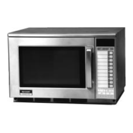
Page 5: Appearance View
12. DOUBLE QUANTITY key 13. DEFROST key 14. NUMBER keys 15. MANUAL/ REPEAT key 16. STOP/CLEAR key 17. MICROWAVE POWER SETTING key 18. START key 19. SET key 20. VOLUME key 21. CHECK key OTHER COMMERCIAL ELECTRICAL APPLIANCE Equivalent potential terminal R-2397... -
Page 6: Operation Sequence
R-2397 OFF CONDITION Closing the door activates all door interlock switches (1st latch switch, 2nd latch switch, 3rd latch switch and stop switch) IMPORTANT When the oven door is closed, the monitor switch contacts COM-NC must be open. When the microwave oven is plugged in a wall outlet (230 volts, 50Hz), the line voltage is supplied to the point A5+A7 in the control panel. -
Page 7: Function Of Important Components
The noise filter assembly prevents radio frequency inter- ference that might flow back in the power circuit. WEAK POINT If the wire harness or electrical components make a short- circuit, this weak point blows to prevent an electric shock or fire hazard. R-2397 OPERATION OF MAGNETRON... - Page 8 R-2397 FUSE F6.3A 250V 1. If the wire harness or electrical components are short- circuited, this fuse blows to prevent an electric shock or fire hazard. 2. The fuse also blows when 1st latch switch remains closed with the oven door open and when the monitor switch closes.
-
Page 9: Servicing
(that is, of the connecting lead of the high-voltage rectifier) against the chassis with the use of an insulated screwdriver. Sharp recommend that wherever possible fault-finding is carried out with the supply disconnected. It may in, some cases, be necessary to connect the supply after... - Page 10 R-2397 TEST PROCEDURE POSSIBLE CAUSE DEFECTIVE PARTS PPROBLEM CONDITION “ . “ does not appear on display when power cord is plugged into wall outlet. Control panel can not accept key in. Fuse F6.3A blows when the door is opened.
- Page 11 R-2397...
-
Page 12: Test Procedure
R-2397 PROCEDURE MAGNETRON TEST NEVER TOUCH ANY PART IN THE CIRCUIT WITH YOUR HAND OR AN INSULATED TOOL WHILE THE OVEN IS IN OPERATION. CARRY OUT 3D CHECK. Isolate the magnetron from high voltage circuit by removing all leads connected to filament terminal. - Page 13 Heat up for 28 sec. a. Primary winding approx. 1.06 b. Secondary winding approx. 57.3 c. Filament winding less than 1 ASYMMETRIC RECTIFIER R-2397 T = 10 C 15 % of the rated output power. 1000g T2˚C HIGH VOLTAGE RECTIFIER...
- Page 14 R-2397 PROCEDURE Isolate the high voltage rectifier assembly from the HV circuit. The asymmetric rectifier can be tested using an ohmmeter set to its highest range. Contact the ohmmeter across the terminals A+B of the asymmetric rectifier and note the reading obtained. Reverse the meter leads and note this second reading.
-
Page 15: Test Procedures
Temperature of “ON” Temperature of “OFF” condition (closed circuit). condition (open circuit). (˚C) This is not resetable type. Above 145˚C This is not resetable type. Above 115˚C R-2397 Indication of ohmmeter (When room temperature (˚C) is approx. 20˚C.) Closed circuit. Closed circuit... - Page 16 R-2397 PROCEDURE MAGNETRON THERMISTOR TEST CARRY OUT 3D CHECKS. Disconnect connector-H from the CPU unit. Measure the resistance of the thermistor with an ohmmeter. Connect the ohmmeter leads to the leads of the thermistor. If the meter does not indicate above resistance, replace the thermistor.
- Page 17 TEST PROCEDURES COMPONENT TEST LETTER L (min) 0.5mH G 10 G 11 G 12 R-2397 0.22 F 4700 pF INDICATION OF OHMMETER Open circuit Short circuit Short circuit...
- Page 18 R-2397 PROCEDURE LETTER If a specific pad does not respond, the above method may be used (after clearing the control unit) to determine if the control unit or key pad is at fault. RELAY TEST CARRY OUT 3D CHECKS. Remove the outer case and check voltage between Pin Nos. 5 and 7 of the connector (A) on the control unit with an A.C.
-
Page 19: Touch Control Panel Assembly
Magnification "1.8" is preset in the double quantity pad. This model has an defrost pad. When the oven is shipped, defrost is set as follows: fig.2. POWER OVEN ON/OFF R-2397 HIGH VOLTAGE TRANSFORMER HIGH VOLTAGE CIRCUIT MAIN BODY SIDE T/C SIDE... - Page 20 R-2397 LSI(IZA646DR) The I/O signal of the LSI(IZA646DR) is detailed in the following table. Pin No. Signal VREF Reference voltage input terminal. A reference voltage applied to the A/D converter in the LSI. Connected to GND.(0V) Temperature measurement input: MAGNETRON THERMISTOR.
- Page 21 Segment Signal Segment P13 ... f P12 ... e P11 ... d P10 ... c P07 ... b P06 ... a Signal similar to P17. Signal similar to P17. Signal similar to P17. Signal similar to P17. R-2397 ß(50Hz) -31(V)
- Page 22 R-2397 Pin No. Signal Segment data signal. Signal similar to P17. 47-48 P07-P06 Segment data signal. Signal similar to P17. Digit selection signal. The relation between digit signal and digit are as follows: Digit signal Normally, one pulse is output in every ß period, and input to the grid of the Fluorescent Display.
- Page 23 4) Attach connectors, electrolytic capacitors, etc. to PWB, making sure that all connections are tight. 5) Be sure to use specified components where high preci- sion is required. R-2397 type or more advanced model.
- Page 24 R-2397 PROCEDURE FOR CHECKING/CLEARING SERVICE COUNTS OF MICROWAVE OVEN The following procedure enables the servicer to obtain the total service counts (cook cycles) for memory cooking, double quantity cooking and defrost. The maximum capacity of the counter is 999,999 counts, above which the counter will reset to "0".
- Page 25 VOLUME "NUMBER" Output Power 100% 100% 100% 100% 100% 100% 100% 100% 100% 100% PHONE DOUBLE DOUBLE DOUBLE DOUBLE : 0.1 sec BUZZER PHONE CHECK CHECK CHECK POWER CHECK CHECK POWER 100% CHECK POWER 100% PHONE DOUBLE DOUBLE DOUBLE R-2397...
-
Page 26: Component Replacement And Adjustment Procedure
R-2397 COMPONENT REPLACEMENT AND ADJUSTMENT PROCEDURE WARNING: Avoid possible exposure to microwave energy. Please follow the instructions below before operating the oven. 1. CARRY OUT 3D CHECKS. 2. Make sure that a definite” click” can be heard when the microwave oven door is unlatched. (Hold the door in... - Page 27 2. Remove the stirrer motor cover by snipping off the material in four portions. 3. Where the portions have been snipped off bend the portions flat. No sharp edge must be evident after removal of the stirrer cover. 4. Disconnect wire leads from the stirrer motor. (See "Positive lock connector removal")
- Page 28 R-2397 CONTROL PANEL ASSEMBLY AND CONTROL UNIT REMOVAL CONTROL PANEL ASSEMBLY REMOVAL The complete control panel should be removed for re- placement of components. To remove the control panel, proceed as follows: 1. CARRY OUT 3D CHECKS. 2. Remove the air intake filter assembly from the base plate.
-
Page 29: Pictorial Diagram
Door release Latch head lever Joint lever Latch lever Latch head meter. (Refer to Microwave Measurement Procedure.) Figure C-4 Latch Switch Adjustments R-2397 Brown wire Power supply cord Cord bushing Monitor switch Latch hook 2nd. - Page 30 R-2397 DOOR REPLACEMENT AND ADJUSTMENT DOOR REPLACEMENT 1. CARRY OUT 3D CHECKS. 2. Remove four (4) screws holding the upper and lower oven hinge to the oven cavity. 3. Remove door assembly with upper and lower oven hinges by pulling it forward.
- Page 31 6. The microwave radiation emission should be meas- ured at any point of 5cm or more from the external surface of the oven. Microwave leakage measurement at 5 cm distance R-2397 15ml of water initially at 20...
- Page 32 R-2397 SCHEMATIC NOTE: CONDITION OF OVEN 1. DOOR CLOSED NOTE: " " INDICATES COMPONENTS WITH POTENTIALS ABOVE 250V. APPEARS ON DISPLAY 2ND LATCH SWITCH 1ST LATCH SWITCH (PRIMARY INTERLOCK SWITCH) Figure O-1. Oven SChematic-OFF Condition SCHEMATIC NOTE: CONDITION OF OVEN 1.
- Page 33 RECTIFIER RECTIFIER R-2397...
- Page 34 R-2397 AT24C04 HZ4C3 C6 ZD2 0.01 HZ12C1 1.8K 1000 0.01 15G471K VRS1 IZA646DR IC-1 2.7K UNIT R93~R101: 1.8K R300 4.7K R200 3.3K 1.1K DOOR 0.01 300K 300K 1.5KF 1.5KF...
-
Page 35: Printed Wiring Board
R101 (J1) R300 R100 (D92) (R92) (D91) (R91) (Q201) (Q200) (J3) (D200) (D74 .R50) (J11) Figure S-3. Printed Wiring Board R-2397... -
Page 36: Parts List
R-2397 Note: The parts marked " " may cause undue microwave exposure. The parts marked "*" are used in voltage more than 250V. REF. NO. PART NO. 1- 1 FH-HZA050WRE0 1- 2 QSOCLA011WRE0 1- 3 FH-HZA049WRE0 1- 4 FPWBFA296WRE0 1- 5... - Page 37 1/4W 1.1k ohm 1/4W 20k ohm 1/4W 3.3k ohm 1/4W 47k ohm 1/4W 470 ohm 1/4W 39 ohm 1/2W 15k ohm 1/4W 4.7k ohm 1/4W 6.8k ohm 1/4W 1.0M ohm 1/4W 8.2k ohm 1/4W 36k ohm 1/4W R-2397 Q'TY CODE...
- Page 38 R-2397 Note: The parts marked " " may cause undue microwave exposure. The parts marked "*" are used in voltage more than 250V. REF. NO. PART NO. 3- 7 PCUSGA380WRP0 Cushion 4- 1 PCUSUA265WRP0 Cushion 4- 2 PDUC-A565WRW0 Exhaust duct...
- Page 39 Screw : 3mm x 28mm 7-35 XNESD30-24000 Nut : 3mm x 2.4mm 7-36 XJPSD40P10000 Screw : 4mm x 10mm 7-37 XOTSC40P12000 Screw : 4mm x 12mm 7-38 LX-EZA004WRE0 Special screw DESCRIPTION MISCELLANEOUS SCRE, NUTS AND WASHERS 10mm 12mm R-2397 Q'TY CODE...
- Page 40 R-2397 HOW TO ORDER REPLACEMENT PARTS To have your order filled promptly and correctly, please furnish the following information. 1. MODEL NUMBER 3. PART NO. 1-28 RFIL-A004WRE0 These ferrite clamps are included in High voltage rectifire assembly 2. REF. NO.
- Page 41 4-46 4-33 7-19 7-18 4-13 6-16 7-13 7-28 6-18 7-25 4-29 4-28 1-22 4-27 1-20 4-50 7-25 1-20 4-42 To conner of lower 7-16 wavegide 7-24 1-26 7-16 4-23 1-11 1-25 4-44 1-13 4-11 1-12 1-10 7-34 1-14 4-14 R-2397...
- Page 42 R-2397 CONTROL PANEL PARTS 3-2-2 DOOR PARTS 5-13 5-19 3 - 7 3-2-3 3 - 2 3 - 5 3-2-1 5-11 5-10 5-11 5-13 3 - 1 3 - 4 3 - 6 3 - 3 1 - 3 5-14...
- Page 43 DOOR PROTECTION SHEET * SPADPA552WRE0 DOOR PAD * SPADF0341WRE0 TRAY HOLDER * SPADPA551WRE0 PRINTING MATER INSTRUCTION BOOK PACKING ADD KIT * CPADBA203WRK0 WRAP COVER PACKING CASE * SPAKCC551WRE0 * Not replaceable items. R-2397...
- Page 44 R-2397 '97 SHARP CORP. (5U0.10E) Printed in Japan...